Working Paper Series ISSN 1177-777X
THE ORIENTING MOUSE: AN INPUT DEVICE WITH ATTITUDE
Mark Apperley and Bill Rogers
Working Paper: 08/2013 November 2013
© 2013 Mark Apperley and Bill Rogers Department of Computer Science The University of Waikato Private Bag 3105 Hamilton, New Zealand
The Orienting Mouse: An Input Device with Attitude Mark Apperley
Bill Rogers
The University of Waikato Hamilton, New Zealand Tel: 64-7-856 2889
The University of Waikato Hamilton, New Zealand Tel: 64-7-856 2889
[email protected]
[email protected]
ABSTRACT This paper presents a modified computer mouse, the Orienting Mouse, which delivers orientation as an additional dimension of input; when the mouse is moved on a flat surface it reports, in addition to the conventional x, y translation, angular rotation of the device in the x, y plane. The orienting mouse preserves important properties of the standard mouse; all measurements are relative and movement is tracked only while the mouse is on its flat surface. If the user lets go of the mouse, leaving it on the surface, its position and orientation do not change until it is touched again. Picking the mouse up and putting it down in a different orientation leaves the angle and position unchanged. While the concept of sensing mouse rotation is not new, our work focuses on movement and navigation in 3D, rather than on precision positioning tasks. We describe a number of sample applications developed to test its effectiveness in this context. Specific features exploited and described include (i) an algorithm for calculating the mouse angle which cancels drift between the two sensors, and (ii) the use of angular gearing which avoids unnatural and uncomfortable hand positions when moving through large angles; informal user testing validates this idea.
ACM Classification: H.5.2 [Information interfaces and presentation]: User Interfaces–Input Devices and Strategies, Graphical user interfaces. I.3.3.1 [Computer Graphics] Hardware Architecture–Input Devices. I.3.6 [Computing Methodologies]: Methodology and Techniques–Interaction Techniques. General terms: Human Factors, Design Keywords: Mouse, Multi-Sensor Mouse, Navigation
1.
INTRODUCTION
Invented by Engelbart in the 1960s [4, 5], the mouse has been the primary device for communicating position information to computers since its appearance as an integral part of the first mass-market graphical user interface [10]. Early mice used mechanical rollers. Since then accuracy and reliability have been improved by using optical sensors. The number of buttons varies, but the most common configurations have one, two or three. The first button provides the fundamental ‘attention’ input – triggering software actions and distinguishing deliberate drag operations from navigation movement. Where a second button is included it most often serves to activate a context menu. There is no standard functionality for third buttons; where present they are used for a variety of application dependent operations. The final common addition is the scroll wheel (often integrated with third button functionality). This is widely used for vertical scrolling and scaling operations. Additional buttons have been incorporated in some mice [3], but usually don’t have fixed function. They are typically programmed on individual preference for fast access to common functions in particular applications – eg: weapon or defense access in computer games. In this paper we focus on the spatial movement capabilities of mice. A basic mouse offers two spatial dimensions of movement, left/right and back/forth on a desk surface, commonly translating to left/right and up/down on the computer screen. So, aside from the various 3D mouse device extensions, most mice offer three buttons and three movement degrees of freedom, two directly mapping spatial movement, one (the scroll wheel) more artificial. Interestingly, the cursor driven by the mouse on the screen is most often an arrow – yet no orientation is implied by the mouse. Standard characteristics of mice include:
the position they specify is retained when they are not moved; they allow rapid movement and also slow precise motion; they operate on a flat surface where the hand can be braced which is good for precision (if not for the health and safety of the human forearm); and they can be operated with the fingers (precise) or by movements of the whole arm (rapid).
Our innovation is the addition of a second optical sensor approximately 5cm from the primary sensor. Tracking movement with the two sensors allows us to detect rotation in addition to left/right or back/forward motion. This extends motion detection to three degrees of freedom (four, counting the scroll wheel).
vated to support rotation in drawing, no such applications are directly described. The authors did introduce the notion of angular gearing, with different modifier keys offering different magnification factors.
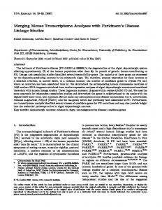
Figure 2: Mouse. Figure 1: Top and bottom views of the prototype Orienting Mouse showing dual optical sensor.
The new motion has similar affordances to the linear motion detection. The mouse stays where it is once positioned, and the angle is preserved if the mouse is stationary. If the orientation is inconvenient the mouse can be lifted off the desk surface and repositioned without altering the sensed angle. The most obvious use of the additional freedom is to allow control of orientation. One inspiration for the development of the device was the difficulty found in navigating in a 3D environment, where movement and viewing directions were locked as one. The orienting mouse potentially removes this constraint, in a very natural way, with movement specified by mouse position, and viewing direction by mouse orientation. A similar advantage can be seen in a First Person Shooter game environment, where it becomes possible to aim by rotating the mouse while shifting left or right by moving the mouse. We have built a number of software demonstrations to show ways of using the mouse, some of which map the new freedom into other ‘in-world’ actions.
2.
BACKGROUND
Perhaps not surprisingly the idea of using two sensors to allow a mouse to detect orientation is not new. Earlier literature, however, is scattered, with variations in terminology and in motivation, which perhaps explains why the technology is not well known or widely used. An early description of a dual sensor mouse [8] was based on mechanical (rotating ball) technology. Although moti-
Movement freedoms of the Orienting
Logitech's Dual Optical MouseMan [9] used a second sensor to improve accuracy and robustness to poor mousing surfaces, and the second sensor was not exploited to provide rotational information. The Yawing Mouse [1] is specifically designed to provide this additional degree of freedom. Usability studies were carried out to assess its potential for a variety of 3D positioning tasks, but these were not focused on specific application domains. Evaluation of the concept is taken further with the TwistMouse [7]. Here it was found that for the given tasks, a scrollwheel mouse performed better than the TwistMouse, but the evaluation was based strongly on the notion of positioning objects in space, rather than viewing and navigating through space. There was also some concern that the basic mouse used was not comparable to contemporary commercial products in its standard mode. The TwistMouse study [7] did make use of a 2:1 angular magnification, as had been proposed earlier [5]. It is suggested that more careful application of this feature will reduce the need for concern about form factor in these devices, which others have suggested [1, 6]. If the mouse need be rotated only by ~ ±20° to achieve any desired action, then the familiar and conventional mouse form factors can be retained.
3.
HARDWARE IMPLEMENTATION
Our prototype is built from a pair of Microsoft optical mice. When the cover and electronics are removed, the base of the mouse is as shown in Figure 3. Note the circular area in the middle on which the lens assembly sits,
and that the rear of the internal framing which supports the circuit board is at (or close to) 45° to the longitudinal axis of the mouse.
independent mice. While one (the front sensor) has full functionality, the other (the rear sensor) lacks buttons or a scroll wheel, and sends only movement data to the computer.
Figure 3: Base of a standard MS Optical Mouse (front at left). Figure 5: Orienting mouse circuit board assembly.
If the rear part of the base is cut away, the middle part of another base can be inserted with the ‘back’ edges of the framing glued together as shown in Figure 4, with relatively minimal overall extension of the mouse ‘package’Figure 4: . This provides a robust base with room for two optical assemblies, longitudinally aligned to within a degree or two, and with both mounted correctly in the sense of having the same geometric relationships between table surface, optical system, sensor and circuit board as an unmodified mouse (with the exception that the second assembly faces backwards – however this can be corrected in the software).
Figure 4: A second detector frame glued onto the rear of the first mouse.
Having the sensors aligned and retaining the correct geometry for the optical components gives a good chance of the two sensors providing similar sensitivity and tracking behaviour. The orienting mouse prototype is completed by reinstalling the full electronic and button system for the front sensor, and that part of the electronics responsible for tracking for the rear sensor (Figure 5). Two independent USB connections are retained – so that, from the computer’s viewpoint, an orienting mouse appears as two
4.
DRIVER SOFTWARE
Ideally an orienting mouse would connect to a computer as a single device, via a single USB cable for example, and would have appropriate device driver software to interpret the combined data from the two sensors. As explained above we were able to develop prototype hardware very quickly by combining two existing mice. The disadvantage of this approach is that our device connects to a computer using two USB cables, as two independent mice. To provide maximum flexibility in developing sample application software, in particular to get access to a familiar graphics environment, we wanted our system to work with the Microsoft Windows 7 operating system. Windows 7 does not natively support multiple mouse interaction: multiple mice can be attached, but their input is pooled to drive a single mouse cursor. A number of methods for retrieving separate input from multiple mice on Microsoft Windows operating systems are reported in the literature. CPNMouse [2] is widely cited, and was used by [7] in the TwistMouse project. It permits multiple mice driving independent cursors. That is not quite the need of our application, but as it gives access to separate data streams from each mouse, it could have been adapted to meet our needs. Unfortunately, it does not work with Windows 7. We tried two other approaches (that probably share the same underlying input mechanism). The first was a project called Microsoft Multipoint which provided library support for multiple mouse pointers in WPF (Windows Presentation Foundation – an XML based user interface system). This worked nicely, and was used for our first prototype. The second method, which gave more flexibility, in that it could be used with a wider range of application software, was to access Window’s Low-Level Mouse interface. This is quite simple to use and provided the
interface required. It allows a user-mode process to intercept mouse messages further back in the operating system processing sequence than usual, where the messages are complete with an identification code for the mouse. We built an interface layer which processes low level messages, combines and interpretes our dual sensor input, and presents an event based interface to the application software. This interface allowed application development with a 3D graphics environment and GDI (the Windows desktop GUI system). In building the interface there were two problems to be addressed. The first was identifying the two ‘mice’ constituting our ‘orienting mouse’. The second was converting the dual sensor input into position/orientation information in a robust manner.
4.1 Mouse Identification When the prototype orienting mouse is plugged in to a laptop, three separate mice are registered in the human interface device configuration – the two parts of the orienting mouse and the laptop touchpad. Sometimes during development there is a fourth mouse; an ordinary mouse for general use. Low level mouse messages carry an identification tag (a small integer), however the tags are not stable. The values assigned depend on the order of plugging in, the history of restarting, etc. The problem then, is to obtain a mapping from device tags to front and rear sensors of the orienting mouse. For the purposes of experimentation we decided that it would an acceptable and flexible solution to re-identify the sensors each time a test application launched. The method we chose was to require a special mouse gesture by the user on application launch; our sample applications prompt for the gesture. The user is required to move the orienting mouse and click its left button. The software simply takes the first two mice it sees moving to be the parts of the orienting mouse. The one that delivers the mouse down message from the user’s click must be the front part of the device, simply because the rear part has no mouse button. Once identification is established, it is assumed that it doesn’t change while the application is running. Clearly, custom hardware and device driver software could avoid the need for the gesture, however with our applications the gesture has a very similar user feel to a ‘click to start’ requirement and did not cause difficulty for users.
4.2 Calculating Orientation Converting double sensor readings to orientation angle proved a challenge for a number of reasons, not the least of which was inconsistency in mouse position data. We discovered that position data was less accurate than anticipated, or rather less complete. A simple experiment shows this effect. If the orienting mouse is moved without rotation using ordinary Windows 7 software, the two sensor inputs should be added. Holding two mice side by side and moving them together gives this result. Howev-
er, the two sensors on the orienting mouse prototype face in opposite directions in both the x and y dimensions. This can be simulated by holding two independent mice with one rotated by 180 degrees. In this situation we might expect movements to cancel each other. Sliding the mouse pair should lead to no cursor movement unless mouse speeds were set differently, in which case the observed movement should be proportional to the difference in mouse speeds. In fact with a pair of conventional mice or with the orienting mouse (whose two devices are set to the same speed) we observe a good deal of jitter and not a small amount of substantive movement. A likely interpretation is that the optical mouse movement measurement is conservative. Possibly it only reports movement when a clear observation of movement occurs from its sensor, dropping ambiguous cases. This would result in loss of movement events. In normal mouse use that might not be noticeable; we move a mouse in the appropriate direction until the cursor arrives at the required destination. If it gets there a little too slowly, we probably don’t notice. When the display depends on the difference of integrated sensor readings, we see jitter, which is much more noticeable. If only translation were involved we might learn to deal with jitter, but when we are trying to calculate angle the result is amplified. Working with the difference of two differences (angle from each of x and y differences) resulted in quite unstable angle estimates. A partial solution was to use a mouse mat to improve tracking. That helped considerably, although it did not eliminate the dropouts. We were left with the need to find a robust way of calculating angles. Our first approach had been to track the two sensors independently and calculate an angle from the coordinate difference. As the positions of the two sensors can drift, the distance between sensors (which is not large) changes significantly and this has a major impact on the angle calculation. The system we finally used for tracking involves two coordinate systems. The first, ‘Sensor Location’, just measures the positions of the sensors. The second ‘Pivot/Angle’ has a single location for the active mouse position and stores the angle separately. Converting between these systems on every update allows us to keep sensor distance constant and gives reliable angle measurements. The Pivot/Angle system is the primary representation and is the one that is made available to application software. It has three values: mouse_x, mouse_y and physical_angle. Each is stored as a float to avoid aliasing effects from frequent small updates. The x axis represents left/right movement of the mouse from the users’ frame of reference and translates to left/right on the screen; y is taken to be the user’s near/far which translates to up/down on the screen. The physical_angle value measures the deviation clockwise from ahead (or vertical on screen) for a line passing through the long axis of the mouse. With a normal mouse, because all movement is relative, there is no reason to think about the point on a mouse that corresponds to its location. However, with the orienting
mouse, it is necessary to think about the pivot point. It makes a noticeable difference if the mouse pivots about its base or about its tip. Accordingly, mouse_x and mouse_y are set to represent the location of the pivot point on the mouse. In the sample applications this is configurable, but has been set to be the midpoint between the sensors for trials. The algorithm for position update is as follows. There are two static parameters (see Figure 6). Sensor_separation is the distance between sensors in micels1; it is set to 800 in the experimental software. The second is lambda, which sets the notional pivot point as a linearly interpolated point between front and rear sensors, 0 corresponding to the front sensor and 1 to the rear. Values less than 0 or greater than 1 can be used if needed. Experimentally, it is set to 0.5, corresponding roughly to the centre of the user’s palm, given typical hand position.
y axis
x axis
front sensor Δy
(front_x, front_y) front sensor Δx
(rear_x, rear_y)
Figure 7: Sensor Location Coordinate System showing offsets for a position update on the front sensor. y axis physical_angle x axis sensor_ separation (mouse_x, mouse_y) lambda * separation
Convert Pivot/Angle to Sensor Location
fx = mx - s cos fy = my - s sin rx = mx + (1 – ) s cos ry = my + (1 – ) s sin Update sensor locations by sensor offsets fx = fx + fΔx cos + fΔy sin fy = fy – fΔx sin + fΔy cos rx = rx + rΔx cos + rΔy sin ry = ry + rΔx sin + rΔy cos Convert Sensor Location back to Pivot/Angle
mx = (1 - ) fx + rx my = (1 - ) fy + ry = atan2(fx – rx, fy – ry) Figure 6: Pivot/Angle coordinate system
Position updates (Figure 7) are driven by arrival of raw mouse offsets. These are usually small values (< 10 micels) and are in the frames of reference of the sensors. In practice there is some additional detail caused by the fact that screen y coordinates number from top to bottom of the screen, and measurements on the bottom sensor are sign reversed. Omitting those details for clarity, the algorithm for applying an update is as follows: where is physical_angle; mx, my, fx, fy, rx, and ry are the locations of the mouse pivot point, the front sensor and the rear sensor; s is the sensor separation; fΔx, fΔy, rΔx, and rΔy are the sensor offsets.
1
A micel is defined as the physical movement required of the mouse to produce a unit change in its measured coordinate.
This approach is robust against sensor offsets not being consistent. Of course, it won’t give the correct result if one sensor drops data, but some rotation will still be detected. Rotation will occur at about half the expected rate, and there will be a small amount of translation. The result seems acceptable. There is progress towards the user’s goal angle, so further movement is likely to reach the goal. The erroneous translation is quite small, and is probably interpreted as failing to rotate about the exact pivot point. The mouse is a large device and the correct pivot point is not intuitively obvious anyway. Most importantly, with the given algorithm, subsequent movement will give rotation consistent with the sensor separation. There is no long term drift in rotation behavior, only the kind of small irregularity in movement and rotation speed with which users must already be familiar. The way in which raw mouse input is delivered to the update algorithm remains a potential a problem. Updates from each sensor are independent, and usually occur in interleaved messages. This might be expected to give a
flittering kind of effect to cursor update. We did experiment a little with smoothing updates over time, but as individual updates are usually small this turned out to be unnecessary. It is likely that the screen update frequency is low enough to provide this kind of filtering for free.
5.
MOUSE ANGLE AMPLIFICATION
As pointed out by [6] there is a problem with using a rounded rectangle shaped mouse. Small angular changes can easily be accommodated by a user, but rotating the mouse by more than about 30 degrees is very uncomfortable. The use of relative angles permits the user to lift the mouse and straighten it, allowing further rotation. However, as with mouse translation, it is not convenient to be required to do this very often. Mouse translation algorithms often include speed variation systems to allow a user to move large distances without requiring too much desk space or having to repeatedly pick up and reposition the mouse. Whilst such ideas probably have validity with the orienting mouse, we opted instead to amplify angular rotation by a fixed amount. In the experimental software this is controlled by a constant ‘angle gearing’ which is set to 4, allowing reasonably comfortable rotation of ±120 degrees (Note that in [7] a factor of 2 is used). There is a need for much study here. In some applications, the idea of relative angle is good. In others, having at least a roughly absolute angle is preferable. In the Brick-Out game we devised (see later), the user needs to keep the mouse mostly pointing straight ahead, and occasionally turn it to the left or right. In particular, it is useful to be able to return to a (straight ahead) home position with little effort. On the other hand, in our Street View™ application and our 3D game application (see later), the user turns to a particular angle, stays there for some time, and may then shift to another angle. There is no fixed sense of ‘home’ angle to which they regularly return, although a given angle may serve as ‘home’ for a short time. The best strategy here is to lift the mouse off the surface and reset it to a temporary home if holding it at a particular angle becomes uncomfortable. Other application variations to consider include the accuracy required for angle position and the size of movements required. It is certainly possible that some acceleration effect might be useful, as might an automatic return to a home angle. Further work with particular applications is needed.
6.
EXPERIMENTAL APPLICATIONS
We have built four applications using the orienting mouse. Previous work with similar devices has focused on manipulation interfaces, particularly in modeling and drawing. Our motivation was a little different. We began by addressing a problem in 3D navigation. Consider the interface typically provided in a first person immersive 3D game. In such a game the user must move about in the play area. Movements may be over a surface, thus in two dimen-
sions, or in a flying game may be in 3D. These games typically use the two dimensions of standard mouse translation to control their view direction. Dragging left/right yaws the player’s view. Dragging up/down allows them to look up and down. Separate controls (usually W and S keys on the keyboard) control movement forward or backward in the current direction of view. The two dimensions of mouse translation thus control movement direction in either 2 or 3 dimensional spaces. It comes at a price however. Any action the user may wish to perform is generally applied to whatever is directly in front of them. Guns fire in the direction of view. 3D games usually offer their players a limited field of view (in the range 45 to 100 degrees). Navigating an obstacle, for example, involves turning away from the object, moving forward, then turning back to see what progress has been made. The process may be repeated several times until satisfactory positioning is achieved. Standard games offer one extension to movement in mitigation of the navigation problem – strafing controls. Typically the A and D keys allow movement left and right in a direction perpendicular to the direction of view. In a combat situation this allows a player to keep directing fire at an opponent whilst moving from side to side. Even in this situation however, the direction of view still doubles as controlling the direction of action. Our hypothesis is that the orienting mouse allows independent control of movement and direction of view. In the case of a first person game, mouse translation can control movement and orientation can control view. If translation directly causes movement, there is a problem in that the amount of movement is limited unless the user is willing to pick the mouse up and reposition it. If mouse translation instead controls speed of movement then unlimited motion is possible, while looking around (and shooting if that is required) in any independently chosen direction. Another situation in which direction of view and motion may be in conflict is Google’s Street View™.As implemented, Street View™ uses click and drag gestures to determine direction of view, and icons on the street to control movement. Moving along a street, looking for a house or shop can involve a sequence of actions similar to the game player trying to move behind an object. Turn to look for movement icons, turn back to look for target, … repeat (possibly with overshoot) until the required viewing point and orientation is achieved. This also seemed to be a good application for the orienting mouse, allowing independent movement and view. The applications we have built partially test these ideas. After an initial application in WPF (which simply allows a user to move an arrow about on a plane and fire bullets in their direction of view) established that we could properly operate the orienting mouse hardware, we built three more functional applications.
The first application is a first person 3D scene in which the player can move and look/shoot independently as described above. A target, the four layered object in the centre of the screen shot (Figure 8) glides about, changing direction at random, in a maze of solid items. The player’s task is to shoot the target with slowly moving bullets. It is useful for the player to keep the target in view and be ready to fire if an opportunity arises, but also necessary to move to find places with a good line of fire. We found that the orienting mouse works reasonably well in this environment. Our implementation gives direct control of movement, so it is necessary to lift the mouse off the ground from time to time to achieve extended movement. It is also necessary to lift the mouse to relieve uncomfortable orientation. An interesting further development in this context would be to experiment with velocity rather than position control, which would avoid the excessive mouse movement. Figure 9: Google Street View™ under control of Orienting Mouse.
Figure 8: First person shooter with Orienting Mouse.
The second application used the orienting mouse to control Google’s Street View (via the API they supply). In this application (Figure 9), mouse angle directly drives view orientation, whilst translation controls jumps between panorama settings. Performance is an issue – the new control mechanism would be better suited to more rapid update. Nevertheless the system achieves its primary objective. It is possible to navigate independently of choosing view angle. This makes it possible usually to maintain context more easily during movement. Further work possible in this system might be to animate the view angle during transitions between view points, in order to further stabilize the area being viewed.
The third application was a two dimensional game – a variant of Brick-Out. In this game a user controls a paddle at the bottom of the screen. A ball bounces off the sides and top of the screen. The user must use the paddle to prevent the ball going off the bottom of the screen. If the ball hits one of the bricks at the top of the screen the brick is removed. The goal of the game is to remove all the bricks. This game has been implemented many times and with many variations (obstacles, different kinds of bricks, power-ups, etc). All implementations the authors have played have a common problem; it is very difficult to control the direction with which the ball bounces off the bat. Usually the direction of bounce depends on the point of impact with the bat, but there isn’t sufficient variation possible to generate a good range of bounce angles. Again and again the ball follows common paths around the screen. There can even be bricks placed in such a way that no bounce will ever reach them. Using the orienting mouse to directly control the angle of the bat (permitting a wide and finely controllable range of angles) seemed to be an interesting variant of the game. Our variant (see Figure 10) also allowed the user to move the bat around the screen, rather than just across the bottom. Too much freedom of movement would make the game too easy, so we added the feature that the bat became invisible when moved higher than one third of the height of the screen. This produced an interesting game. From the player’s perspective, the annoying behavior in which bounce patterns have limited variation was eliminated, without trivializing game play.
8.
Figure 10: Brick-Out play, modified to show bounce.
Orienting Brick-Out was informally tested with members of the public.
7.
INFORMAL USABILITY TEST
The Brick-Out application was put on display as part of the Computer Science exhibit on a University Open Day and visitors were encouraged to try playing. Some just worked from instructions on the table. Others were encouraged by staff on the stand, who explained briefly what to do. The software recorded mouse movement and game outcome in game play sessions. Visitors on the day were high school students and their parents, and probably most of those who tried to play were students although no explicit demographic data was recorded. The recordings cover roughly 70 games. Some recordings are ambiguous in that a visitor may have tried moving the mouse, but not made a serious attempt to play. By observing playback of visitor games with a duration over 10 seconds, we see that 80% of plays showed good control of mouse position and orientation. The remaining 20% showed a variety of issues. Some lost control because they moved the bat forward to where it became invisible; some tried to move the bat to hit the ball rather than let it bounce. These issues are more a result of usability issues with the game, than with the device. No more than 5% seemed to have any serious issue with operating the orienting mouse. There was no formal questionnaire, but staff talked briefly with many of the players. Most found the device interesting and enjoyed their experience. No-one expressed surprise or uncertainty about the angle amplification. Whilst the evidence is not definitive, our observations provide positive support for the usability of the orienting mouse, consistent with observations reported by other studies of like devices.
CONCLUSIONS
We have described the implementation of an orienting mouse, one which provides conventional x-y position information, but in addition, rotation about the vertical axis. While this concept has been discovered to be not new, our motivation, and applications, we believe are better suited to the attributes of this mouse architecture. Whereas in other reported trials of similar devices, applications and usability tests have focused on positioning tasks which require precision coordination between position and angle, our motivation, and our sample applications, have focused on movement and navigation – controlling one aspect of movement with the x-y information, and another with the rotation information. This does not require precise coordination between the two aspects of the mouse movement, and appears to avoid some of the issues discovered with earlier studies [7]. On reflection, it does seem obvious that rotating the mouse is a gesture which will not necessarily occur around its predefined pivot point, so is thus highly likely to also trigger some translation, less than ideal for positioning tasks. A further contribution of our work has been the algorithm for determining the pivot/angle data, which avoids drift and gross errors. We also utilized a higher angle gearing than others, which works well with the continuous gesture associated with movement and navigation control.
9.
REFERENCES
[1] Rodrigo Almeida and Pierre Cubaud. 2006. Supporting 3D window manipulation with a yawing mouse. In Proceedings of the 4th Nordic conference on Human-computer interaction: changing roles (NordiCHI '06), Anders Mørch, Konrad Morgan, Tone Bratteteig, Gautam Ghosh, and Dag Svanaes (Eds.). ACM, New York, NY, USA, 477-480. [2] CPNMouse: Multiple Mice in Windows http://www.xmarks.com/site/cpnmouse.sourceforge.net [3] Digital Trends. 2013: Razer Naga review. http://www.digitaltrends.com/computer-micereviews/razer-naga-review/ [4] Englebart, Doug (1968): Demonstration (on-line). http://sloan.stanford.edu/MouseSite/1968Demo.html [5] English, W.K.; Engelbart, Douglas C.; Berman, M.L. 1967. Display-Selection Techniques for Text Manipulation. Human Factors in Electronics, IEEE Transactions on , HFE8, 1, 5-15. [6] Daniel Fallman, Anneli Mikaelsson, and Björn Yttergren. 2007. The design of a computer mouse providing three degrees of freedom. In Proceedings of the 12th international conference on Human-computer interaction: interaction platforms and techniques (HCI'07), Julie A. Jacko (Ed.). Springer-Verlag, Berlin, Heidelberg, 53-62. [7] Hannagan, J. & Regenbrecht, H. 2008. TwistMouse for Simultaneous Translation and Rotation. Technical Report. HCI group. Information Science Department. University of Otago, Dunedin, New Zealand.
[8] I. Scott MacKenzie, R. William Soukoreff, and Chris Pal. 1997. A two-ball mouse affords three degrees of freedom. In CHI '97 Extended Abstracts on Human Factors in Computing Systems (CHI EA '97). ACM, New York, NY, USA, 303-304.
[9] Macworld (2001): Logitech introduces Mouseman Dual Optical. http://www.macworld.com/article/1019382/logitech.html [10] Vectronics. 2013. The evolution of the Apple mouse. http://vectronicsappleworld.com/macintosh/mouse.html