INTERNATIONAL CONFERENCE ON ENGINEERING DESIGN, ICED'09 24 - 27 AUGUST 2009, STANFORD UNIVERSITY, STANFORD, CA, USA
THE P3 PLATFORM: AN APPROACH AND SOFTWARE SYSTEM FOR DEVELOPING DIAGRAMMATIC MODEL-BASED METHODS IN DESIGN RESEARCH David C Wynn, Seena MT Nair and P John Clarkson Engineering Design Centre, University of Cambridge ABSTRACT Many issues in design and design management have been explored by building models which capture the relationships between different aspects of the problem at hand. These models require computer support to construct and analyse. However, appropriate modelling tools can be time-consuming to develop in a research environment. Reflecting upon five design research projects, this paper proposes that such projects can be facilitated by recognising the iterative and tightly-coupled nature of research and tool development, and by attempting to minimise the effort of solution prototyping within this process. Our approach is enabled by a software platform which can be rapidly configured to implement many conceivable modelling approaches. This configurability is complemented by an emerging library of modelling and analysis approaches tailored to explore design process systems. The platform-based approach enables any mix of modelling concepts to be easily created. We propose it could thus help researchers to explore a wide range of questions without being constrained to existing conventions for modelling – or for model integration. Keywords: P3 Platform, configurable diagrammatic modelling, design system 1 INTRODUCTION Complex products and their development processes may be viewed as systems, whose different aspects can be modelled as networks of interactions between elements in different domains. For example, the structure of components and sub-systems in a product, the network of communication between personnel in an organisation, and the flows of information between tasks in a design process may all be described in this way. In the literature, many approaches have been proposed to explore, support or improve the design process and its management by building such models. Developing these approaches, and applying them to problems of realistic complexity, often requires specialised computer software suitable for manipulating large data sets. However, our experience in a number of research projects has indicated that developing suitable software tools can be difficult in a research environment – because software development is time-consuming and requires skills that many researchers do not possess. This paper argues that tool-intensive design research projects can be facilitated by recognising the iterative and tightly-coupled nature of research and tool development and by aiming to minimise the effort of solution prototyping and revising within this process. The approach is enabled by a configurable software platform we have developed, refined and applied over several years and through a number of research projects. The software platform is based on a graphical diagramming interface which should be familiar to users of standard office productivity suites and which several projects have indicated is robust enough for deployment in industry. This platform can be configured without programming to implement novel modelling frameworks, which must be specified in terms of the elements allowed in a model and the constraints upon how they can be connected. The user interface is constructed automatically from this configuration to provide an experience tailored to the modelling approach at hand. The data sets created using this interface can be accessed through Java plug-ins which appear as options and menu buttons in the tool, thereby allowing customised analysis tools such as simulation codes to be developed and integrated with little or no user interface development. The
ICED’09/578
software platform is thus intended to provide an alternative to general-purpose diagramming tools or spreadsheets as a way to prototype systems modelling and analysis methods. We have also developed implementations of some of the main modelling notations, simulation methods and other analytical tools proposed in the literature for analysing design process systems. The configuration files for these notations and the source code for these analytical tools, which we intend to make available to the design research community, can provide a starting point for developing new research ideas – for instance to extend an existing discrete-event simulation model to explore the relationship between process duration and product quality. In addition to assisting the development of new methods, we propose that adopting our approach could ease the dissemination of methods to industry by enabling researchers who are not software professionals to produce production-quality implementations of their ideas. The argument is organised as follows. In Section 2 we draw upon recent research projects to motivate the paper and identify requirements to support such projects. Section 3 describes the approach developed to address these requirements and Section 4 describes key features of the software implementation. Section 5 illustrates its application by discussing a project in which the approach was used to develop a new model-based method to support process improvement, focusing on the management of engineering change processes. Section 6 highlights the contributions of the paper to the literature and of the reported software to the design research community, compares our work to other publications and tools in this area, and identifies opportunities for further research. Section 7 concludes. 2
BACKGROUND AND MOTIVATION
2.1 Reflections on five design research projects The research reported in this paper was motivated by five research projects in which one or more of the authors were closely involved. The projects were each conducted over a period of between one year and three years in the Cambridge EDC since 2002. They all focused on the development and application of systems modelling approaches, either aiming to draw insights about design processes or to improve or support them. The studies investigated: • How discrete-event simulation models can be used to support design planning [1]. • The theory of design process robustness, through process simulation experiments [2]. • The application of process modelling to redesign the conceptual design processes of a large aeroengine manufacturer to incorporate life-cycle engineering issues [3]. • How the engineering change process can be supported through a traceability model which captures requirements, functions, components and information flows in the design process [4]. • How the computational synthesis of product architectures can be used to support human designers in early concept development [5]. Although these projects each had different objectives, with foci ranging from theoretical desk research through to application of modelling methods in industry, they each involved construction of system models based on modelling languages tailored to the specific problems at hand. Reflection upon these studies led us to an understanding of the needs of design researchers in developing such modelling approaches, and in particular highlighted the problems faced in developing prototype software implementations to apply and evaluate the research results. Since several of these projects included industry case studies, they also led to an understanding of the needs for such tools from an industry perspective – high-level requirements which arose from the need to represent and/or support design practice. These inter-related requirements are discussed in more detail below, prior to introducing the platform-based approach we developed to meet them. 2.2 A description of the research process followed in the five projects Reflections on the projects outlined in Section 2.1 indicated that such research typically requires: • Identifying stakeholders and articulating the objectives of the research or support method. • Eliciting general knowledge to identify factors which govern the domain of concern, with respect to the objectives. • Developing a modelling framework to represent elements in the domain, as appropriate to the factors and objectives of interest.
ICED’09/578
• Developing an implementation to allow manipulation and analysis of models. • Eliciting specific knowledge of the system to be modelled, and building a model. • Analysing the model to explore research issues and/or look for potential improvements. This is a very general description, since the specific foci of the research projects governed what was achieved in each activity. In all cases, however, the research involved significant and disordered iteration as conceptual frameworks and emerging methods were refined during their development. For example, elicitation of specific domain knowledge repeatedly led to refinements in the general domain understanding, necessitating changes to the modelling framework and thus to the implementation concept. This highlighted the iterative and responsive nature of tool-intensive design research and the tight coupling between research activities and software development within it. 2.3 The importance of software development in the research process Our research support approach described in forthcoming sections is based on the observation that, during the five projects discussed in Section 2.1, one of the most time-consuming aspects of the research process was software development. In particular, although the analysis algorithms developed by the researchers (such as Monte-Carlo simulation) were relatively straightforward to implement, developing the robust user interfaces needed to manipulate and visualise the large models necessary to reflect industry practice required expert knowledge and software development skills which many researchers may not possess. We concluded that supporting the implementation activity within the method development process would allow effort to be focused on other phases of the process, thereby enabling more refinement iterations within the time available and ultimately resulting in more mature and appropriate support methods. 2.4 The need for both rapid development and standardisation of modelling tools In the projects discussed in Section 2.1, the way we approached development of prototype modelling tools was influenced by three main considerations: 1. The need to construct the minimum implementation required to demonstrate a modelling idea. 2. Subsequently, the need to harden the user interface sufficiently to allow application and evaluation of the emerging research, either in an industry context or in the laboratory. 3. The need to iteratively refine the implementation as new ideas were generated. Therefore, the primary objective for software development in these projects was rapid concept development, hardening and refinement, rather than the implementation of ‘minor’ features such as specialised user interface components. In addition, it was identified that the ability to easily modify existing modelling tools in a standardised way could add significantly to their potential to support future research. Although commonplace in mainstream software development, such flexibility is often not incorporated in research tools due to the development overhead it incurs. As a result, even within our co-located research group, it has often been easier to ‘begin again’ when extending modelling systems previous researchers had developed, rather than to build upon the earlier implementations. 2.5 Summary To summarise, through reflections upon experience gained in five design research projects we identified that the development of new design support methods could be supported by recognising the iterative and incremental nature of method development and by reducing the effort required for tool development within this iterative practice. Such reduction in effort could be achieved through software support allowing researchers to rapidly generate, evaluate and modify implementations of their ideas. 3 AN APPROACH BASED ON SOFTWARE PLATFORM CONFIGURATION Based upon the observations of design research projects described in Section 2, we developed a way to approach such projects through iterative refinement of modelling tools via configuration of a software platform. Because it is based on configuration, rather than programming, this approach allows modelling frameworks to be rapidly refined while ensuring that the implementing tools remain stable and useable. It also allows tools constructed using the approach to be easily extended or customised by other researchers – since only knowledge of the configuration approach is required, and not knowledge of detailed, specific implementation code. However, a configuration-based approach limits the flexibility of the system to those options which were considered when designing the configuration options. Hence, it is critical to ensure the configuration language allows expression of the full space of ICED’09/578
modelling frameworks whose development the platform-based approach is intended to support. Following sub-sections describe the configuration approach we developed to achieve this. 3.1 Overview of the configuration approach All modelling frameworks comprising elements and relationships between them may be expressed as labelled digraphs. Furthermore, the tools which implement these frameworks all present the user with views of the model as network diagrams, matrices (tables) and trees. The data structures underlying these views can be expressed as topological transformations of the digraph defining the model. Taking this perspective, our approach is therefore based on expressing a given modelling framework by constraining the elements and connections which are allowed in models of that type. This is similar to ontology modelling, but differs from ‘pure’ ontology-based approaches in that it describes not only the data structures of a modelling framework, but also the views used by the modelling environment to represent information and the user interface which is provided to manipulate it. We refer to this combined approach of data modelling and user-interface specification as linkage meta-modelling [6]. In overview, the approach requires definition of each view in the modelling application as a perspective of the model. Each perspective transforms the digraph structure of elements and linkages in a model in order to obtain another digraph which comprises a subset of the elements and linkages in the original. For instance, a tree perspective operates upon a model to generate a tree structure 1 . This abstract data structure is then used as the basis of an interactive user interface component which allows the model to be explored and manipulated from the underlying tree perspective. Many such perspectives are defined to compose the user interface of a modelling framework. This linkage meta-modelling approach, and the perspectives framework, is described in detail elsewhere [6]. In the present paper, we report on significant extensions to the earlier work by describing how linkage meta-models can be used to configure diagrammatic modelling languages. 3.2 Detail of the configuration approach for diagrammatic modelling frameworks In overview, our approach assumes that a diagrammatic model of any type is comprised of worksheets, nodes and node ports, edges and constraints: 1. Worksheets. Each worksheet may contain multiple nodes and edges. Worksheets may be used in a graphical sense – to split a large model for easier navigation and printing – and/or in a logical sense – such that sections of the model on different worksheets have different meaning. Multiple worksheets may be created and may optionally be nested within one another. 2. Nodes and node ports. Each node on a worksheet is an instance of a particular class defined in the linkage meta-model. In our approach, model instances are referred to as elements and model classes are referred to as schemas to avoid confusion with the Java language used in the implementation. An element schema determines the data fields which are presented to the user to edit the properties of elements of that type. Each such data field is defined by a property schema, which governs how data is collected and validated by a widget in the user interface. For instance, the double-value-in-range property schema prompts the user to enter a value between a specified minimum and maximum, via a text field and a slider. This can be used, for example, to collect probability values associated with instances of a class. The schema itself can be configured, in this case, to specify the minimum and maximum values which users may enter. Element schemas also determine how nodes are rendered in the diagramming view, by combining simple geometric primitives which render rectangles, ellipses, text strings etc. Every element schema must also define one or more node ports. Each node port is a part of the node geometry which has a particular meaning in the modelling framework. For instance, an arrow connected to the left of a system dynamics rate element indicates a flow inlet. Connecting an edge to the top of the same element is used to denote an influence. 3. Edges. Edges connect one node port to another, either on the same node or on two different nodes. The type of an edge is determined by an edge schema defined in a similar way to element 1
Each perspective is specified as a set of declarative rules which governs the behaviour of a recursive algorithm which traverses a model digraph node-by-node. The algorithm attempts to ‘match’ the node under attention in the model graph against a pattern defined in each rule; the matching rule determines what action is taken in the view graph which is under construction, then may recurse over connected nodes in the model graph. The configuration of perspective rulesets is described in greater detail in [6].
ICED’09/578
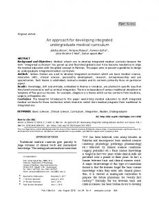
schemas. Edges may thus have their own properties. For instance, an edge schema may define a property schema ‘connection strength’. Edges also have display properties allowing the line style, color and arrowhead styles to be configured. 4. Connection constraints. Constraints determine whether an edge can be created between two given node ports, and if so, the class and initial property values for the edge. For instance, a system dynamics model disallows connections from node port of class inlet to inlet, from inlet to outlet, and from outlet to outlet. Connections created from an inlet to an outlet are allowed, and are created using the edge schema “System Dynamics Flow”. Element schemas, edge schemas and connection constraints are specified in configuration files which are used by the software implementation to dynamically construct a data model and user interface for the specified modelling framework. To illustrate, Figure 1 shows the configuration for an element schema representing a rate in a system dynamics model, alongside an instance of such a rate as displayed in the diagramming interface and the dialog which is dynamically generated to edit its properties.
Configuration file
Node displayed in diagramming interface
Dialog generated from configuration file
Figure 1. Configuration file for a node schema
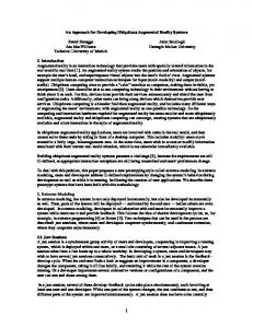
The organisation of objects in the data model generated from these configuration files is outlined diagrammatically in Figure 2. In this representation, each filled shape represents a Java object as stored within the software implementation. The top layer of objects represents the linkage meta-model itself, created from the configuration files to define the classes of element which can be modeled as well as the various constraints, properties, UI configuration etc. The centre layer indicates the data structure of a particular model constructed in the tool. Each object in this layer represents a particular aspect of the diagrammatic model. Since they are defined by configuration and not by programming, each object in this layer is of the same Java class and holds a reference to the schema in the upper layer, which defines its type and thus the fields associated with it. The structure of the centre layer is constrained by the meta-model of the top layer (note that constraints are not shown in Figure 2 for clarity). The bottom layer indicates how this example model would be rendered in the diagramming interface, thereby showing the relationship between the 1) Java objects in the instance data and 2) the diagram nodes, node ports and edges. The interface we developed for manipulating these models is discussed in Section 4. 3.3 Summary Due to space constraints, this paper can only provide a very high-level overview of the flexibility of configuration provided by our approach. Building upon the basic concept outlined above, a wide range of configuration options have been developed through an incremental process in which options required in the tool were revealed through the development of a library of meta-models required for our various research projects. The emerging library is discussed further in Section 4.
ICED’09/578
P3Element
PaletteElementPort
Meta-model (showing schema definitions only)
Flow
Influence
PaletteElement
Rate
Worksheet
Flowmeter
Instance data (conforms to constraints defined in meta-model)
Diagrammatic view (a perspective of the instance data, developed through topological transformation as detailed in Wynn and Clarkson, 2008)
Rate
Flowmeter
Figure 2. Illustrative example showing the data structure of a model created in the approach
4 IMPLEMENTATION OVERVIEW Consideration of the research projects discussed in Section 2.1 revealed a number of high-level requirements which guided the system development. These can be broadly classified as either research- or application-oriented, and are indicated in Table 1. The approach was implemented in the ‘P3 Platform’ software. A key requirement for the implementation was to provide an interface which can be seen by end-users as a modelling solution competitive with general-purpose commercial diagramming tools. Significant effort was thus dedicated to ensure the flexibility and familiarity of the interface. It incorporates standard features such as copy/paste/group/align as well as new diagramming features which address some of the main problems encountered with general-purpose diagramming tools when constructing the large models which are required to model complex systems in practice. Table 1. Illustrative example showing the data structure of a model created in the approach Research-oriented requirements Flexible – allowing modelling tools to be rapidly prototyped and modified through an iterative process, with a minimum of programming. Modular – allowing analysis codes and other extensions to be developed in a well-defined way that allows for incremental and organic extension of the system. Library based – providing implementations of standard modelling and analysis approaches, which can serve both as stand-alone tools and as the starting point for development of more sophisticated, or domain-specific, analyses. Interoperable – allowing data extraction and/or modification without programming. ICED’09/578
Application-oriented requirements User-friendly and familiar – being capable of producing high-quality graphics and flexible diagramming, with interface broadly comparable to general-purpose diagramming tools like Visio. Production-quality – providing an implementation that could be deployed in industry to allow evaluation of a particular modelling approach. Ability to create integrated, multi-faceted models – an ability few tools provide beyond the standard UML CASE tools, which cannot resolve all system modelling problems encountered in engineering practice.
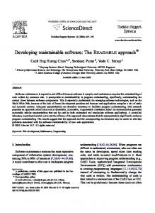
A number of standard modelling approaches and algorithms have been implemented using the platform to date, as shown in Table 2. Screenshots showing models created using a selection of these approaches are shown in Figure 3. The discussion in this paper focuses on diagrammatic models. However, the software also allows construction of matrix-based models. Any diagrammatic model can be interchangeably viewed and manipulated as a hierarchical Dependency Structure Matrix (DSM) [10], in which each node appears as a row/column heading in the matrix and each edge as a mark connecting the element in the column to that in the row. Partitioning, sequencing and clustering algorithms can be applied to these matrices. Applied Signposting process model Simulation codes are specific to each meta-model
System dynamics model
Petri net process model
Integrated product-process-rationale model
Contact and Channel product model
Figure 3. Some example configurations of the software provided in the meta-model library Table 2. Approaches in the meta-model and analysis code library, with references to publications describing application of similar approaches to design Applied Signposting process model + simulation [1] Petri net process model [7] + simulation
System dynamics model + simulation [8] Queueing model + simulation ICED’09/578
IBIS-style rationale modeller [9] Design Structure Matrix (DSM) [10] + Partitioning, clustering, sequencing and an implementation of Browning’s design process simulation model [11]. Change Propagation Model + simulation [12] Contact and Channel product model [13]
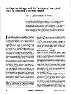
5 ILLUSTRATIVE EXAMPLE This section illustrates the platform by discussing an example in which it was used to develop an approach to support management of engineering change processes. The change management approach was developed by a graduate student whose only programming experience was gained through an undergraduate engineering degree. The student’s research was concerned with helping designers and managers make more informed choices about the different options associated with engineering change and its implementation. A modelling approach was developed to: 1) capture knowledge relevant to assessing change implementation; and 2) to use this knowledge as part of a systematic method to assess the duration of change implementation processes [4]. In the approach, knowledge capture is approached by building graphical models of elements in the requirements, functions, components and design process domains, and indicating how these elements are interrelated. The underlying concept is that knowledge captured in such a model allows traceability analysis in which proposed requirement changes can be traced through the functions and components which implement them to identify their implementation processes [4]. Beginning with this concept for the modelling framework and analysis approach, the following steps were undertaken to develop a linkage meta-model: 1. Element schemas were created to define the modelling framework. Their properties and ports were created. 2. Edge types and their properties were identified and edge schemas were created. 3. Edges which were not allowed (e.g. directly between tasks and requirements) were prohibited. 4. Generic features of the platform which were not required were disabled to simplify the modelling interface (e.g. resources, calendars, etc.) This provided the diagramming notation used for knowledge capture. A Java plug-in was then developed to perform the traceability analysis. This was based on the change propagation algorithm from the code library – extended to allow analysis which considers the multiple domains outlined above and thereby allowing the estimation not only of change propagation risk as originally reported by Clarkson et al. [12], but also the duration of the redesign process. In overview, the plug-in operated as follows: 1. Access instance data using method calls to the platform API, traversing nodes via relations. 2. Present a sequence of dialogs, coded as part of the plug-in to prompt the user for input to identify which of the possible propagation paths will occur for the change case under consideration. 3. Populate data structure used by the change propagation algorithm in the library, and use a modified version of this algorithm to perform the enhanced propagation analysis. 4. Present results to the user using customised dialogs, written using standard Swing components. These steps of meta-model and plug-in development are presented sequentially, but in practice were iteratively revisited as the student developed his ideas through application of the approach to an example case of aircraft structure design. Some screenshots from the resulting application are shown in Figure 4, illustrating the layers of the traceability model alongside part of the dialog sequence.
Figure 4. A modelling and analysis tool developed using the approach [4] ICED’09/578
6 DISCUSSION AND REFLECTION To recap, this paper was motivated by the need to provide an approach to support the development of model-based methods in design research. The requirements for the approach and the software platform were based on insights drawn from several research projects conducted in UK industry since 2002. Our approach was developed to support the development of research prototypes of the type which are commonly reported in the design literature, and is not intended as an integrated information management system. Hence our current focus of attention does not include ‘heavyweight’ implementation concerns such as explicit support for integrating code developed in multiple implementation languages, explicit support for integration of modelling tools into existing environment, or explicit support for multi-user or distributed modelling. Our research focus surrounding this software platform has not been to develop a single, integrated model, but rather to explore the relationships between and limitations of existing approaches with the aim to better understand how they can be used to improve practice. 6.1 Comparison to other work in this area A number of authors have published work related to the approach presented in this paper. For instance, Bracewell et al. [14] propose the CaeDRe approach intended to allow the prototyping of solutions early in the research process. This comprises a methodology [14], which is based on that of Blessing et al. [15], and a collection of software components, eight programming languages and integration tools (described in [16]). Their system differs from ours in that it is based on integration, rather than configuration and thus requires significant software expertise to apply. It also does not provide the integrated user interface which is central to our approach. Our approach of viewing design systems as networks of elements and designing support systems through an iterative process of in-situ refinement is also similar to that taken by Subrahmanian et al. [17] in developing the n-dim infrastructure for ‘agile design information systems’. They focus on supporting the agile development of IT systems to support collaboration in product development, allowing companies to develop and maintain IT solutions dynamically in response to changes in the environment of design tasks, organisational structure, people and design technology [18]. Many of the concepts described by Reich et al. have strongly influenced our approach. However, the n-dim user interface as reported in the 1999 paper [18] appears to have limited flexibility by today’s standards. As a formal description of an information domain, the approach presented in this paper is also related to ontology specification languages such as Ontolingua [19] and OWL [20]. Similarly, our software platform is related to ontology modelling tools such as Protégé-2000 [21]. Corcho and Gómez-Pérez [22] review these approaches, noting the different expressive capabilities of each and how this is related to their intended applications, with particular emphasis on automatic inferencing. The objective of the research presented here is to support development of interactive modelling tools. Therefore, the expressiveness of our approach was designed to facilitate user interface development instead of the automated reasoning about a knowledge base which is the objective of much ontology research. In a previous paper [6] we began to develop an approach to address some of these limitations. In the earlier work we focused on matrix-oriented methods such as the DSM and MDM approaches, arguing that these approaches are well-suited to modelling and visualising the dense networks of dependencies found in many aspects of the design process system. Loomeo, another tool focusing on matrix-based modelling and analysis, is described in [23]. Matrix-based approaches provide powerful analysis tools, and can be very effective for working with models of strongly-connected systems. However, in many respects they are less intuitive than the diagramming languages such as SADT, UML, IDEF, OPM, etc. which are in widespread use. The approach presented in this paper focuses on this type of diagrammatic modelling, although it also allows data to be manipulated in matrix form. Apart from supporting the development of formal modelling frameworks, a key benefit of our software over general-purpose diagramming tools is to enable ‘intelligent’ analysis of graphical models by applying the simulation and analysis approaches in the emerging code library. 6.2 Summary of contributions We view the main contributions of this work as follows. Firstly, our software system provides a diagramming interface which is flexible and robust enough to allows researchers to quickly test out new modelling ideas without requiring time-intensive UI programming. It is then possible to interface with the system to extract data sets and analyse them using plug-in code. The applications of this basic ICED’09/578
approach are not specific to design research. The second benefit, which we believe is of specific interest to the design research community, is the growing library of design-oriented modelling and analysis approaches we are developing within this platform as part of our ongoing research. We hope that this emerging library of design-oriented meta-model definitions and analysis codes could provide a starting point for future research. For instance, it is relatively straightforward to take an existing design process simulation approach, add new parameters to the data model, and modify the simulation code to explore a new set of research questions. Since the ‘front end’ modelling interface of the resulting tool is provided entirely by our system, which has been refined and debugged over several years, it is relatively quick and easy to produce tools of sufficient quality to allow evaluation and, ultimately, deployment in industry. The third benefit is the possibility to use this library and extensible platform to investigate how different modelling and analysis approaches could be integrated to draw together their different capabilities. The possible benefits to be gained through modelling design systems across multiple domains – and by taking different perspectives of these domains – have been discussed widely in the engineering design literature (e.g., [24]). The modelling platform and library reported in this paper offer a starting point for further research in this area. We have been using our system to support a range of research projects in Cambridge during the last several years, and believe it could be useful to others in the design research community. Hence we intend to make our software platform and emerging meta-model library freely available for academic use, and to provide open-source code for many of the associated simulation and analysis tools. The paper thus reports a contribution to the design research community as well as to the literature. 6.3 Further work Apart from ongoing refinement of the software we have reported in this paper, a number of opportunities for more fundamental research have arisen from its development. These include: • A more complete meta-model and code library. The meta-models and analysis codes developed thus far (Table 2) have been opportunistically implemented to meet the needs of particular research problems we have recently investigated. A significant area for future work is to perform a thorough review of modelling and simulation tools applied in design research and use this as the basis of a more comprehensive library. Furthermore, it would be useful to organise the approaches into a hierarchy according to their information requirements, thereby allowing the automated or semi-automated translation of models between languages. However, this may require significant conceptual challenges to be addressed. For instance, a task in the ‘Signposting’ design process model [25] represents an item of work with cost and duration, which has required input information and produces certain output information. In this model, a task may only be attempted when input information becomes available at a given confidence level. Thus Signposting assumes that tasks reside in a ‘bucket’ and are attempted only when the project context allows. Workflow models, in contrast, assume that tasks are attempted when specified predecessors are completed. Thus, although the information requirements of these two approaches are similar, the conceptualisation of tasks and processes is very different and transfer–even comparison–of models between them is not a straightforward problem. Similar issues of conceptual and semantic difference arise when considering other related modelling approaches. • Understanding how appropriate modelling approaches can be selected. Looking beyond the present paper, our recent research has highlighted the need for a pluralistic approach to modelling and improving design systems. Each modelling approach has its own characteristic strengths and weaknesses; no one model or modelling framework can be universally applied. An important future research issue is thus to explore how the most appropriate modelling tools can be selected from the wide range which are available and then applied in a way which recognises their limitations. The approach presented in this paper should provide one starting point for research in this area, by enabling the rapid development of customised approaches which could better meet the requirements of particular modelling applications and allowing easy switching between them. • Linking process simulation and analysis codes. A related opportunity is to integrate design process simulation codes to explore issues for which no approach is ideal in isolation. For instance, it is possible to envisage ‘nesting’ structured workflows within the dynamic tasks in a Signposting model. Many interesting problems could be explored in this way, since design processes can be perceived to behave differently at different levels of resolution and different ICED’09/578
modelling/simulation approaches. For instance, the example outlined above might be appropriate to the case we describe in [1], where fragments of workflow within a component design process could be easily defined, but the sequence of attempting those fragments was disordered and opportunistic, responding to changes in designers’ focus of attention. Through its configurable modelling interface and code library, the toolset discussed in this paper could provide a starting point to explore the different ways process modelling approaches could be integrated. 7 CONCLUSIONS Many approaches proposed in design research are based upon diagrammatic models representing different aspects of technical systems and the processes and organisations through which they are designed. Such approaches can be difficult to develop, since they require software expertise to create prototype tools sufficiently robust and user-friendly for evaluation and deployment in industry. This paper reports on the ongoing development of a platform-based approach intended to resolve this issue. The development has drawn on and supported research projects undertaken in Cambridge since 2002. The paper makes the following main contributions. Firstly, a contribution to the literature, in which we have demonstrated through these projects that the iterative research process can be supported through a configurable software platform and identified the requirements for that software. Secondly, we discuss a data-oriented contribution to the community, rather than to the literature – the software itself, which we intend to make available for academic use alongside a library of meta-model and analysis codes we have developed to implement some of the main model-based approaches reported in design research. Alongside the software, these meta-models and their associated analysis codes could significantly assist researchers wishing to further develop existing approaches in the design literature. Many such approaches reported today are based on application of or extension to a relatively small number of fundamental algorithms, such as DSM clustering/partitioning/sequencing, PERT-type discrete-event simulations, system dynamics simulations and queuing simulations. Thus, we believe a library of standard codes can provide a useful resource and starting point for exploring a wide variety of problems. REFERENCES [1] Wynn D.C., Clarkson P.J. and Eckert C.M. A model-based approach to improve planning practice in collaborative aerospace design. In ASME IDETC/CIE 2005. [2] Chalupnik M.J., Wynn D.C., Eckert C.M. and Clarkson P.J. Analysing the relationship between design process composition and robustness to task delays. In DESIGN 2008, Dubrovnik, Croatia. [3] Bell C.P., Wynn D.C., Dawes W.N. and Clarkson P.J. Using meta-data to enhance process simulation and identify improvements, In 16th International Conference on Engineering Design, ICED’07, Paris, France. [4] Ahmad N., Wynn D.C. and Clarkson P.J. Estimating the Process Cost of Implementing Engineering Change Alternatives. In 2nd Nordic Conference on Product Lifecycle Management, NordPLM’09, Goteborg, Sweden. [5] Wyatt D.F., Wynn D.C. and Clarkson P.J. Synthesis of product architectures using a DSM/DMM-based approach. In 10th International DSM Conference, DSM’08, Stockholm, Sweden. 11th-12th November 2008. [6] Wynn D.C. and Clarkson P.J. Linkage meta-modelling to support the development of design process improvement tools. In International Symposium on Tools and Methods of Competitive Engineering, 2008. [7] McMahon C.A., Xianyi M. A network approach to parametric design integration. Research in Engineering Design, (1996) 8, pp. 14-32. [8] Ford D.N. and Sterman J.D. Dynamic modeling of product development processes. System Dynamics Review, 14(1), 1998, pp. 31-68. [9] Bracewell R.H., Ahmed S. and Wallace K.M. DRed and design folders: a way of capturing, storing and passing on - knowledge generated during design projects. In ASME International Design Engineering Technical Conferences, IDETC'04, Salt Lake City, Utah, USA. [10] Eppinger S., Whitney D., Smith R. and Gebala D. A model-based method for organizing tasks in product development. Research in Engineering Design, 6, 1994, pp. 1-13. [11] Browning T.R. and Eppinger S.D. Modeling impacts of process architecture on cost and schedule risk in product development. IEEE Transactions on Engineering Management, 49(4), 2002. ICED’09/578
[12] Clarkson P.J., Simons C.S. and Eckert C.M. Predicting change propagation in complex design. Journal of Mechanical Design, 126 (5), 2004, pp.765-797. [13] Albers A., Matthiesen S. and Ohmer M. An innovative new basic model in design methodology for analysis and synthesis of technical systems. In 14th International Conference on Engineering Design, ICED ’03, Stockholm, Sweden. [14] Bracewell R.H., Shea K., Langdon P.M., Blessing L.T.M. and Clarkson P.J. A methodology for computational design tool research. In 13th International Conference on Engineering Design, ICED’01, Glasgow, UK. [15] Blessing L.T.M., Chakrabarti A. and Wallace K.M. A design research methodology. In 10th International Conference on Engineering Design, ICED’95, Prague, Czech Republic. [16] Bracewell R.H. and Shea K. CaeDRe: A product platform to support creation and evaluation of advanced computer aided engineering tools. In 13th International Conference on Engineering Design, ICED’01, Glasgow, UK. [17] Subrahmanian E., Reich Y., Konda S.L., Dutoit A., Cunningham D., Patrick R., Thomas M. and Westerberg A.W. The n-dim approach to creating design support systems, In ASME DETC 1997, Sacramento, California. [18] Reich Y., Konda S., Subrahmanian E., Cunningham D., Dutoit A., Patrick R., Thomas M. and Westerberg A.W. Building Agility for Developing Agile Design Information Systems. Research in Engineering Design (1999) 11 pp. 67-83. [19] Gruber T.R. A translation approach to portable ontology specifications, Knowledge Acquisition 5(2), 1993, pp. 199-220. [20] Bechhofer S., van Harmelen F., Hendler J., Horrocks I., McGuinness D.L., Patel-Schneider P.F. and Stein L.A., OWL web ontology language reference, World Wide Web Consortium, 2004. [21] Noy N.F., Fergerson R.W. and Musen M.A. The knowledge model of Protégé 2000: Combining interoperability with flexibility, in Dieng, R. and Corby, O. (Eds.), Knowledge Engineering and Knowledge Management: Methods, Models and Tools, Springer, 2000, pp. 17-32. [22] Corcho O. and Gomez-Perez A. A roadmap to ontology specification languages, in Dieng, R. and Corby, O. (Eds.), Knowledge Engineering and Knowledge Management: Methods, Models and Tools, Springer, 2000, pp. 80-96. [23] Maurer M., Boesch N.-O., Sheng G. and Tzonev B., A tool for modelling flexible product structures: MOFLEPS, In 15th International Conference on Engineering Design, ICED’05. [24] Andreasen M.M. The Theory of Domains. In Workshop on understanding function and function to form evolution. Cambridge, UK, 1992. [25] Clarkson P.J. and Hamilton J.R. Signposting: a parameter-driven task-based model of the design process. Research in Engineering Design, 12(1), 2000, pp. 18-38. Contact: David Wynn University of Cambridge Department of Engineering Trumpington Street Cambridge. CB2 1PZ United Kingdom. Email:
[email protected] URL: http://www-edc.eng.cam.ac.uk/people/dcw24.html
Dr. David Wynn holds an MEng in Engineering and Computing Science from the University of Oxford and a PhD from the University of Cambridge. He is now a Research Associate in the Cambridge University Engineering Department and a Fellow of Homerton College, Cambridge where he teaches Mechanical Engineering. Seena Nair received a BEng in Electronics and Communication Engineering from Mangalore University and gained 7 years experience developing commercial software prior to joining the Cambridge Engineering Design Centre in 2002. Professor John Clarkson received a BA and PhD from Cambridge University and worked at PA Consulting for 7 years before returning to Cambridge in 1995. He was appointed Director of the Engineering Design Centre in 1997 and Professor of Engineering Design in 2004.
ICED’09/578