Of the three primary advantages of block transfer, fast pipelined data .... of a known large amount of data from one processing node to another, in which case moving the data in large messages ..... Closer analysis of contention and the ability to ...
The Performance Advantages of Integrating Message Passing in Cache-Coherent Multiprocessors Steven Cameron Woo, Jaswinder Pal Singh and John L. Hennessy Computer Systems Laboratory Stanford University Stanford, CA 94305
Abstract We examine the performance benefits of integrating a mechanism for block data transfer (message passing) in a cache-coherent shared address space multiprocessor. We do this through a detailed study of five important computations that appear to be likely candidates for block transfer. We find that while the benefits on a realistic architecture are significant in some cases, they are not as substantial as one might initially expect. The main reasons for this are (i) the relatively modest fraction of time that applications spend in communication that is amenable to block transfer, (ii) the difficulty of finding enough independent computation to overlap with the communication latency that remains even after block transfer, and (iii) the fact that long cache lines often capture many of the benefits of block transfer. Of the three primary advantages of block transfer, fast pipelined data transfer appears to be the most successful, followed by the ability to overlap computation and communication at a coarse granularity, and finally the benefits of replicating communicated data in main memory. We also examine the impact of varying important network parameters and processor speed on the relative effectiveness of block transfer, and comment on useful features that a block transfer engine should support for real applications.
i
ii
Contents 1 Introduction
1
2 Structuring Communication in a Shared Address Space
1
3 System Architecture and Simulator
3
4 The Applications and Methodology 4.1 Choice of Applications : : : : 4.2 Experimental Methodology : :
: : : : : : : : : : : : : : : : : : : : : : : : : : : : : : : : : : : : : : : : : : : : : : : : : : : : : : : : : : : : : : : : : : : :
5 Results for Base Architectural Parameters 5.1 The Fast Fourier Transform : : : : : : : 5.2 Blocked Dense LU Factorization : : : : 5.3 Blocked Sparse Cholesky Factorization : 5.4 Ocean Simulation : : : : : : : : : : : : 5.5 Radix Sort : : : : : : : : : : : : : : : : 6 Varying Architectural Parameters 6.1 Varying Network Latency : : : 6.2 Changing Processor Speed : : :
: : : : : : : : : : : : : : : : : : : : : : : : : : : : : : : : : : : : : : : : : : : : : : : : : : : : : : : : : : : : : : : : : : : : : : : : : : : : : : : : : : : : : : : : : : : : : : : : : : : : : : : : : : : : : : : : : : : : : : : : : : : : : : : : : : : : : : : : : : : : : : : : :
: : : : : : : : : : : : : : : : : : : : : : : : : : : : : : : : : : : : : : : : : : : : : : : : : : : : : : : : : : : : : : : : : : : :
7 Discussion and Conclusions
4 4 5 5 5 9 12 13 14 15 15 16 17
iii
List of Figures 1 2 3 4 5 6 7 8 9 10 11 12 13
FFT: Algorithm and Transpose : : : : : : : : : : : : : : : : : : : : : : : : : : : : : : : : : : FFT: Unblocked BT versus Blocked LS (8KB Cache) : : : : : : : : : : : : : : : : : : : : : : FFT: Blocked BT versus Blocked LS (8KB Cache) : : : : : : : : : : : : : : : : : : : : : : : : Subpartitioning to Allow Overlap of Communication and Computation : : : : : : : : : : : : : FFT: Subpartitioning to Allow Overlap of Communication and Computation (8KB Cache) : : : Blocked Dense LU Factorization. : : : : : : : : : : : : : : : : : : : : : : : : : : : : : : : : : LU: Comparison of Various Replication Strategies (256x256 Matrix, B=16, 8KB Cache) : : : : LU: Comparison of BT Communication Methods versus LS No Replication (256x256 Matrix, B=16, 8KB Cache) : : : : : : : : : : : : : : : : : : : : : : : : : : : : : : : : : : : : : : : : Cholesky: Comparison of BT Buffering Strategies versus LS No Buffering (TK15, B=32, 16KB Cache) : : : : : : : : : : : : : : : : : : : : : : : : : : : : : : : : : : : : : : : : : : : : : : : Ocean: Comparison of BT versus LS : : : : : : : : : : : : : : : : : : : : : : : : : : : : : : : Radix: Comparison of Fastest BT Sort versus Fastest LS Sort (65,536 Integer Keys) : : : : : : FFT: Impact of Varying Network Speed (65,536 Complex Reals, 8KB Cache; also compare with base architecture results in Figure 5) : : : : : : : : : : : : : : : : : : : : : : : : : : : : : Impact of Varying Processor Speed on LU and Cholesky (compare with base architecture results in Figures 8 and 9, respectively). : : : : : : : : : : : : : : : : : : : : : : : : : : : : : : : : :
iv
6 7 8 8 9 9 10 11 13 14 15 16 17
List of Tables 1 2 3
Performance Advantages of Different Communication Models : : : : : : : : : : : : : : : : : : Important Simulation Parameters and their Values in the Base Architecture. : : : : : : : : : : : The Applications. : : : : : : : : : : : : : : : : : : : : : : : : : : : : : : : : : : : : : : : : :
v
2 4 5
1 Introduction A shared address space with coherent caches has been shown to provide an effective communication abstraction for multiprocessors. The shared address space greatly simplifies the parallel programming task—particularly for irregular, dynamically changing communication patterns—by making communication implicit rather than requiring explicit communication in the user program. Also, automatic coherent caching of shared data often reduces the implicit communication to levels that yield good performance. One shortcoming of existing cache-coherent shared address space architectures is that they have relied on implicit communication through loads and stores in the shared address space as the only means of communication. While this works well for fine-grained data sharing patterns, applications often require the movement of a known large amount of data from one processing node to another, in which case moving the data in large messages is likely to be more efficient than moving the data one cache line at a time through processor loads and stores. Such block transfer of data also naturally brings with it the replication of communicated data in main memory, and the ability to overlap the communication with computation more effectively at a coarser granularity. All these advantages are increased as communication latencies become larger and communication bandwidths become smaller relative to processor speeds. Since block data transfer is clearly not mutually exclusive with a cache-coherent shared address space, and since the core mechanisms for moving data with low latency and high bandwidth are very similar for cache coherence and block transfer, architects have begun to design machines with hardware support for both a cache-coherent shared address space and block transfer of data [1]. Structuring communication in large blocks is clearly crucial on current message-passing machines (and workstation networks), since the overheads and latencies of sending messages are very high. However, it is not clear what the role of coarse-grained messages is on tightly coupled, hardware cache-coherent shared address space architectures. Several questions arise about (i) the performance advantages of selectively using block transfer over relying completely on a standard load-store shared address space model, (ii) how these advantages vary with processor, memory system and network performance, (iii) the desirable capabilities of a block transfer mechanism (other than the ability to move large contiguous pieces of data efficiently), (iv) whether or not applications or algorithms have to be changed substantially to use block transfer on top of cache coherence, and (v) the implications for the programming model for such an architecture, since block transfer can clearly be provided by various mechanisms including explicit message passing and software distributed shared memory protocols [3, 4]. In this paper, we focus primarily on the performance advantages of using block transfer and how they change with architectural parameters. We address block transfer features and algorithmic changes where they are relevant in the applications we consider. We do not explicitly address the programming model question, but use an explicit memory copy primitive for block transfer to enable us to study performance without the overheads of a specific high-level software system. Section 2 discusses different ways to structure coarse-grained communication in a cache-coherent multiprocessor with a block transfer facility, and the performance advantages that can potentially be obtained by using block transfer. Section 3 describes the architecture and simulation environment that we use in our experiments. In Section 4, we discuss our choice of applications, our experimental methodology and the values we use for various architectural parameters in our base machine. Section 5 discusses the results for different applications on the base machine. The impact of varying network and processor speed parameters is addressed in Section 6. Finally, Section 7 summarizes our main conclusions.
2 Structuring Communication in a Shared Address Space Given a cache-coherent shared address space machine with a facility for block transfer, there are several ways in which the communication of a large chunk of data might be organized. The two primary issues are: (i) who initiates or requests the communication, i.e. is it receiver-initiated or sender-initiated, and (ii) is the communication done through standard loads and stores of shared data or through block transfer. The key sources of performance difference among the four resulting communication models are:
�
Fast pipelined transfer of large amounts of data. This is achieved in the models that use block transfer, since the overhead of message request, initiation, and management of a data message is incurred only 1
once per large block rather than once per cache line, and since the datapath between main memory and the network is shorter through the block transfer engine than it is through the main processor.
�
Overlap of communication with computation or with other communication.
�
Replication of communicated data in main memory.
There are other issues, such as the ability to naturally combine synchronization and data transfer in a single message with block transfer, but these are less important for our applications and we do not consider them. Two points bear emphasis. First, we are by no means restricted to using only one communication model in a given application, but are free to use whichever model is most appropriate for any particular communication. In fact, we rely on the implicit, usually receiver-initiated, load-store model for all but block communication, thus retaining the major advantages of a cache-coherent shared address space. Second, given that we have a shared address space, the most appropriate way to do block transfer is not through a send operation to a processor that requires a matching receive, but by performing a memory copy from the source directly into the destination data structures.
Initiator Receiver Sender
LoadStore
— — —
— Overlap Replication
Block Transfer
Fast Transfer — Replication
Fast Transfer Overlap Replication
Table 1: Performance Advantages of Different Communication Models
Table 1 summarizes how the three performance advantages naturally fit into the communication models. A couple of notes on the table follow. First, overlap of communication with computation can be achieved in receiver-initiated models as well, by using advanced techniques such as prefetching, multithreading and even dynamic scheduling with relaxed consistency models. The last two techniques are beyond the scope of this paper, and we comment on prefetching in the discussion at the end of the paper (Section 7). Among the loadstore models, the sender-initiated can overlap communication with computation more easily, since the latency of write misses is much easier to hide than that of read misses. However, sender-initiated communication is not as natural to the load-store model as receiver-initiated, and its potential advantages rely on the relationships between communication latency and other architectural features such as write buffer depth and sophistication. We do not discuss sender-initiated load-store communication in this report, but note that with realistic write buffers, we found it to not help too much over a receiver-initiated load-store model. Second, replication in main memory can also be obtained in the receiver-initiated load-store model, either explicitly by the user or automatically by the system 1 . We assume that it must be done explicitly by the user. We experiment with explicit replication at different levels, in every case getting to essentially the level at which all important communicated data are replicated locally. We also explicitly replicate certain seemingly 1 Automatic mechanisms include cache-only memory architectures (COMA), page replication by the operating system, or replication by the runtime system at the granularity of user-defined “objects”. Pages are often too coarse a granularity for replication, coherence and data movement, especially in the presence of fine-grained data sharing. And objects have problems too: the objects that are useful from the “object-oriented” programming elegance points of view (encapsulation, modularity etc.) are often not appropriate for communication, and communication in a given phase of a program often requires only a part of a logical object.
2
insignificant but frequently referenced read-only shared variables that do not get automatically replicated in main memory in our system2 . Block transfer can be done either into the receiver’s cache or into its main memory. We assume block transfers into main memory for two reasons. First, particularly when communication is overlapped with computation, pushing into the cache might interfere with data that the receiving processor needs, and potentially generate more communication. Second, the replication in main memory is useful if the data need to be reused later but do not stay in the cache. Replication in main memory thus goes hand-in-hand with our block transfer communication. Although receiver-initiated block transfer does not naturally provide overlap like sender-initiated, it may have advantages when: (i) the sender does not know where to send data, (ii) it is important to restrict the amount of replication in main memory, and (iii) the receiver can better determine the order in which it needs to receive messages than the sender can determine the order in which its destinations need to receive them. We experiment with receiver-initiated block transfer only when some of the above are important issues (see Section 5.3). Thus, the two models that we focus on mostly are receiver-initiated load-store, which is the most natural way of programming a cache-coherent machine without block transfer, and sender-initiated block transfer, which is usually the natural way to do block transfer. Given the advantages in Table 1, the goal of our block transfer versions is to reduce communication costs through fast data transfer and replication, and hide the remaining costs as far as possible by overlapping communication with computation. We shall examine the extent to which we are able to achieve this goal, and analyze the specific reasons why we fall short (such as the overheads of block transfer, contention with load-store memory accesses and coherence transactions, and the inability to overlap communication with computation).
3 System Architecture and Simulator Every node in the cache-coherent multiprocessor we assume contains a processor with a single-level cache, a directory controller, a network interface, and an equal fraction of the main memory. The directory controller contains a programmable control “processor” that is used to process local memory accesses, standard directorybased cache-coherence protocol transactions and block transfers. The network interface connects the node to a 2-dimensional, bidirectional mesh network. The architecture is based closely on the FLASH architecture that is currently being designed. To perform a block transfer, the processor initiating the transfer notifies the directory controller on the source node. We assume a fairly sophisticated block transfer engine which allows us to specify different strides at the source and destination (this is quite feasible with a programmable directory controller, since all the functionality does not have to be provided in hardware). Block transfers are handled entirely by the directory controllers, so that both the source and destination main processors may continue to compute while the transfers are in progress (although they may contend for resources with the transfers or have to wait for the transfers to complete for other reasons). The source directory controller retrieves cache-line sized memory blocks of data from main memory, if they are not cached, and transmits them in a pipelined fashion to the receiving node, where the controller stores these lines into main memory at the specified addresses. Synchronization for message arrival is performed by checking the status of a flag associated with the transfer, or through higher-level constructs such as barriers. No restrictions are placed on the number of message transfers that a processor can be involved in at a given time. Multiple transfers from a source are interleaved at a cache line granularity. Processors are not allowed to send block transfer messages to themselves. Three important issues arise when implementing block transfer on top of a cache-coherence protocol. First, the data (addresses) involved in the block transfer may be cached by the sending node and/or the receiving node, which adds time to the block transfer for retrieval and invalidation of cached data. In fact, in general the most up-to-date copy of a data item may be cached at a third node (and the “source” processor initiating the transfer may not even be the node on which the storage for the data is allocated). This general case requires block-transferred data to be kept globally coherent, which is complicated to implement and expensive 2 These variables can otherwise cause substantial extra communication and hot-spotting if they are replaced in the cache. This in fact can often be an important advantage of systems that replicate automatically (such as COMA machines), particularly with direct-mapped caches and for such variables that are not strictly read-only and therefore must be kept coherent as well.
3
at runtime. Early designs of block transfer protocols have therefore restricted themselves to assuming that data are sent only from the node where their storage is allocated, and ensuring only that the sender and receiver’s caches stay coherent with their respective local memories [6]. These restrictions actually suffice for all our versions of the applications we consider, and we comment on cases where versions of the applications would violate the assumptions and complicate block transfer (see Section 5.2, for example). The second issue is that the directory controller is needed both for transactions related to load-store accesses as well as for block transfer, which may occur simultaneously. Since block transfer messages are likely to be large, and we do not want to stall other accesses that are short, we give priority to other accesses and allow them to interrupt and temporarily suspend a block transfer. Third, transfers may include partially written cache lines (memory blocks). At the destination, the controller must retrieve the line and merge it with the valid portion of the transmitted line, which also increases message transfer time. The architecture is simulated using the Tango event-driven reference generator [8]. Our detailed, variable-latency memory system simulator models contention at the directory controller and memory system, but not in the network itself. An invalidation-based cache-coherence protocol similar to that used in the Stanford DASH machine [9] is simulated. Processors are forced to block on read misses, but write buffering hardware is included to reduce processor stalls on write misses. To help reduce miss latencies, speculative reads are performed at the home node at the same time that line state is checked. The processor is assumed to have a 100% hit rate in the instruction cache. Parameter Main Processor Clock Rate Internal Data Bus Width Queueing Delay into and out of Directory Controller Memory Block State Lookup Time Memory Block Remote Request Message Construction Time Overhead for Cached Blocks at Sender and Receiver Memory Block Access Time (independent of block size) Network Width (each direction) Network Topology Network Clock Rate Network Cache Line Header Size Message Latency Between Adjacent Nodes Block Transfer Message Startup Time
Value 100 MHz 64 bits 8 cycles 15 cycles 10 cycles 5 cycles 25 cycles 16 bits 2D Mesh 200 MHz 32 bytes 5 cycles 100 cycles
Table 2: Important Simulation Parameters and their Values in the Base Architecture.
Several parameters affect the time to service memory accesses and block transfers, some of which are listed in Table 2. The time required for a block transfer also depends on the three issues discussed above. In performing a block transfer, accesses to main memory and data transfer into the network are assumed to be pipelined. The effective pipeline stage time for block transfer operations is therefore the greater of the time to retrieve a line from memory and the time to push a line and its associated header into the network.
4 The Applications and Methodology 4.1
Choice of Applications
We do not try to study a “representative” mix of parallel applications and determine the “average” effectiveness of block transfer. Rather, we choose a few applications and computational kernels based on two criteria: (i) they appear likely to be aided by block transfer, and (ii) they are each representative of important classes of applications/algorithms for parallel computing, so that it makes sense for architectures to include features to support them efficiently, even if other applications may not benefit from these features. 4
Kernel/Application p Radix n Fast Fourier Transform Blocked Dense LU Factorizaton Blocked Sparse Cholesky Factorization Ocean Simulation with Multigrid Solver Radix Sort
Representative of Convolution/Transform Methods Dense Linear Algebra Sparse Linear Algebra Regular Grid Iterative Methods Sorting
Table 3: The Applications.
The applications/kernels we study are listed in Table 3. Our ocean simulation application is a scalable version of the Ocean application in the SPLASH suite [11]. It uses a different solver and partitioning. The blocked Cholesky factorization is also a more scalable alternative to the panel Cholesky kernel in SPLASH. It is statically scheduled for locality of reference, unlike the dynamically scheduled code in SPLASH. We do not use either of the other two scalable applications in SPLASH (Water and Barnes-Hut), since they (i) are well-suited to fine-grained cache coherence, (ii) have very low communication volume, and (iii) do not benefit from replication in main memory since their working sets are small. Barnes-Hut also cannot be easily structured for block transfer.
4.2
Experimental Methodology
For each application, we examine the performance gains obtained by sender- or receiver-initiated block transfer over the receiver-initiated load-store model. We start with the best versions of the applications that we can develop for the load-store model, discuss different ways to incorporate block transfer, and examine the performance benefits of replication, overlap and fast data transfer, trying to isolate their effects as much as possible. To help isolate effects, we also examine the receiver-initiated load-store model with explicit replication. In each application, we identify the primary reasons that limit block transfer from achieving its goal of reducing and hiding all the communication costs. We also examine how the effectiveness of the block-transfer models changes with the data set size and number of processors in each application, and comment on how the results might scale to larger problems and machines. We choose cache sizes based on the working sets of the applications, so that the cache size in our simulations is large enough to accommodate the working set if this would indeed be the case in practical problems running on real machines. We also vary the cache line size in all cases, since larger lines can in many cases provide some of the advantages of block transfer even in the load-store model. In the individual application sections that follow, we use a base set of machine parameters that might be found on a machine that can be built today. Then, in Section 6, we examine the effects of varying some key parameters on the advantages of block transfer in these applications. The variations we study reflect possible technology trends or other types of systems that provide different communication latencies and bandwidths than the base architecture. In particular, we examine the effects of using (i) a slower network, (ii) a faster network, and (iii) a much faster processor with the same local memory access time and network. The important machine parameters we consider, as well as their values in the base architecture, are shown in Table 2. The cache line size is varied between 32 and 128 bytes. The processor is assumed to take 1 cycle per instruction. With 64 byte cache lines, the latency for a local read miss is about 40 cycles, that for a remote read miss is about 120 cycles, and the node-to-network interface has a peak bandwidth of about 380 MB/sec for block transfer, which is actually quite an aggressive network for this processor.
5 Results for Base Architectural Parameters 5.1
The Fast Fourier Transform
The Fast Fourier Transform (FFT) is a dominant computation in a wide variety of fields ranging from signal processing to climate modeling. The FFT analyzed in this section is a complex 1-D version of the six-step 5
p
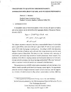
FFT algorithm described in [2]. This algorithm utilizes a high radix (radix n, where n is the number of data points) to optimize memory referencing and communication behavior by minimizing the number of passes through the data set. The data set for the FFT consists of the n complex data points to be transformed, pnx and pn another n complex data points referred to as the roots of unity. Both sets of data are organized as p matrices in the radix ncomputation. The six steps of the algorithm are shown in Figure 1(a). Both the data matrix and the roots of unity matrix are partitioned among processors in contiguous chunks of rows, with a processor’s partition of rows being allocated in its local memory 3 . The roots of unity matrix is read-only once it is initialized. The first row of this matrix is accessed heavily by all processors, and is therefore replicated at the beginning of the program. This helps performance substantially since it eliminates p hot-spotting. This is the only replication that is of any use in the FFT. The working set of each 1-D FFT ( n points) is assumed p to fit in the cache—which is true with our 8KB cache for both the problem sizes that we use—since even if npoints don’t fit a smaller radix can be used within the 1-D FFTs to make the working set fit. Long cache line doesn’t cross traversal order
Long cache line crosses traversal order The Six−Step FFT Algorithm Owned By Proc 0
1. Transpose data matrix 2. Perform 1−D FFT on each row of data matrix 3. Apply roots of unity to data matrix 4. Transpose data matrix 5. Perform 1−D FFT on each row of data matrix 6. Transpose data matrix
Owned By Proc 1 Owned By Proc 2 Owned By Proc 3
patch Source Matrix
(a) Algorithm Steps
Destination Matrix
(b) FFT Transpose Phase
Figure 1: FFT: Algorithm and Transpose The only communication is in the transpose phases, which require all-to-all communication ofp a large amount of data. Figure 1 illustrates how the transpose is done. Contiguous subcolumns in the pn rows
p
p
assigned to a processor are grouped into patches of size pn -by- pn , which are transposed and placed into the proper location of the destination matrix. Every processor transposes one patch locally, and sends one patch to each of the other processors in the system. Let us look at the different ways of structuring the transpose communication. Receiver-initiated load-store Although there is no reuse of individual words in the transpose, with long cache lines it makes sense to block the transpose to take advantage of the spatial locality afforded by long lines in the source matrix (or temporal locality at the cache line level). The source matrix is viewed as being divided into blocks of size B by B, where Bis proportional to the number of cache lines (not elements) that fit in the cache. When a processor moves from one subcolumn of a source block to the next, if a cache line straddles these subcolumns then the elements of the second subcolumn are likely to already be in the cache. This makes a big difference to performance, reducing overall execution time by 40% for a 64K-point FFT with 16 processors, 8KB caches and a 128-byte cache line (and reducing transpose time from 50% of overall execution time to only 15%). We use this blocked transpose FFT as our reference point in subsequent comparisons. Sender-initiated block transfer: Since replication of communicated data is not an issue in the FFT, and since receiver-initiated block transfer ends up looking almost exactly like one of our sender-initiated cases (other than the one additional request message per block), we do not discuss receiver-initiated results for space reasons. Let us examine sender-initiated block transfer. Even with our fairly sophisticated block transfer primitive, the transposition of a patch cannot be entirely performed in a single block transfer message: It requires both specifying a number of elements at each stride point, and more importantly, telling the transfer engine to transpose the data layout. One way to do the block transfer is to send one subcolumn of a patch at a time 3 We have structured the roots of unity matrix differently than in [2], arranging it so that a processor mostly needs to access the rows that are in its own partition; this yields vastly superior performance on a parallel machine.
6
��
100.0 �
|
80.0
� ��
� � �
� � �
� �
�
�� �
���
|
60.0
|
40.0
|
20.0
|
Execution Time
|
120.0
|
140.0
|
0.0 | 1
� � � | 2
| 4
� � �
LS BT, 128B Lines BT, 64B Lines BT, 32B Lines
| | | | 8 16 32 64 Number of Processors
16,384 Complex Reals
Figure 2: FFT: Unblocked BT versus Blocked LS (8KB Cache) and put it in a subrow at the destination (thus using different strides) 4 . Figure 2 shows the performance of this version. Unless otherwise specified, all our graphs (in all applications) show performance relative to the receiver-initiated load-store (LS) version. When a graph shows three curves labeled by line size, the y-axis value of a point for each curve is the application’s execution time for that number of processors and that line size, normalized to the execution time with the same number of processors and the same line size in the receiver-initiated LS version. Thus, every point shows at a glance how much better or worse the version being compared is relative to the receiver-initiated LS version for the same set of parameters. While the block transfer (BT) version in Figure 2 does well for small cache lines and small numbers of processors (for this small problem), it performs much worse as the line size and number of processors increase. There are three reasons for this. First, the transposes using BT are not blocked for cache line reuse like the LS version. Second, the destination node receives many partially valid memory lines, since a cache line may straddle consecutive subcolumns, which decreases performance as discussed earlier. Both these differences exist only for cache lines larger than a single element. Finally, more processors for the same problem implies smaller patch subcolumns, and hence smaller transfers and an even greater impact of transfer overhead. All of these overhead problems can be alleviated by using the flexibility afforded by the programmable directory controller to write a special block transfer handler that blocks the transpose in the controller itself. Figure 3 illustrates the performance improvement from utilizing such a handler in the FFT. The FFT (or any matrix transpose) is thus clearly an example of more sophisticated support being needed in the block transfer system than simply the ability to move large chunks of data efficiently. Figure 3 reveals some expected trends. First, the effectiveness of block transfer is greatest at the “sweet spot” where the communication to computation ratio is high enough that speeding up communication is important, and yet the individual block transfer size is large enough that the overheads of block transfer don’t dominate. This sweet spot in terms of number of processors clearly increases with increasing data set size. As long as the messages are large enough, larger data sets don’t help the magnitude of the improvement with block transfer much for a given number of processors (since the achieved communication bandwidth improvement mostly depends on the ratio of the remote read miss time to the block transfer pipeline stage time (see Section 3); however, larger data sets allow block transfer to be effective for larger numbers of processors. Second, as in almost all our applications, the relative advantage of block transfer is larger with smaller cache lines. This is mostly because larger cache lines capture some of the effects of block transfer anyway, and sometimes because as partitions become small larger cache lines can lead to partially written cache lines and false-sharing, which hurt block transfer substantially. So far, the only advantage of block transfer we have explored is the fast transfer of data. No replication was needed, and we have not tried to overlap the remaining communication costs with 1-D FFT computation (the only overlap has been between computing the local patch transpose and sending the patches to remote 4 Another possibility is to transfer a block in a non-transposed way, and have the receiver transpose each received block before using it. Transferring a block in a single message requires more than a stride capability: It also requires the ability to specify the number of elements at the stride points. In addition this method also requires the user to either use a buffer per processor to receive data into or use a temporary buffer to transpose the received blocks in the destination matrix, and requires the main processor to do the transpose. Finally, the blocking in the controller method discussed next is the best method anyway.
7
Execution Time
Execution Time
| | | | 8 16 32 64 Number of Processors
80.0 60.0 40.0
20.0 | 1
|
| 4
LS BT, 128B Lines BT, 64B Lines BT, 32B Lines
��
100.0 �
|
| 2
� � �
�� �
|
|
20.0 | 1
�� �
� ��
���
|
|
40.0
���
� � �
|
60.0
���
|
80.0
� ��
120.0
|
|
��
100.0 �
���
|
|
120.0
16,384 Complex Reals
���
� � �
� � � | 2
| 4
�� �
�� �
�� �
LS BT, 128B Lines BT, 64B Lines BT, 32B Lines
| | | | 8 16 32 64 Number of Processors
65,536 Complex Reals
Figure 3: FFT: Blocked BT versus Blocked LS (8KB Cache)
destinations). The FFT can, however, be rewritten to overlap communication with computation. To do this, the rows of a processor’s partition are divided into subpartitions that can be efficiently transposed. The idea is illustrated in Figure 4. Once the 1-D FFTs for a subpartition have been performed, the component subpatches of that subpartition can be block transferred. While the directory controller is sending these transfers, the main processor continues performing one-dimensional FFTs on its next subpartition. Since the working set of the 1-D FFT fits in the cache, there should not be too much contention between load-store requests and the block transfer. The main potential disadvantage of this approach is that more messages are sent, since subpatches are smaller than patches or blocks. Matrix
Cache Line Subpartition width determined by number of elements per cache line
Subpartition 0 Subpartition 1 Before Transpose
Transpose of subpartition 0 can be overlapped with computation of one−dimensional FFT’s for rows in subpartition 1
After Transpose
Figure 4: Subpartitioning to Allow Overlap of Communication and Computation Figure 5 illustrates the performance of this method. Compared to the results in Figure 3, we see that subpartitioning and overlap is helpful when there are at least a few subpartitions per processor (that is, when p is small relative to n), but actually hurts performance slightly when there is only one subpartition per processor (since there is overhead involved in managing the subpartitioning). Closer analysis of contention and the ability to fill the communication time with overlapped computation reveals the following results. Contention effects between block transfer and load-store accesses are very small (only a few percent of execution time in the worst of our cases), and diminish with larger cache lines since the load-store accesses incur less misses. The effects tend to diminish with increasing numbers of processors (since there is less work to overlap) and are expectedly larger in the subpartitioning case than in the no overlap case. However, the idle time waiting for communication to complete is smaller in the subpartitioning case, and this has a much greater impact on performance. The problem is that the 1-D FFT’s do not take as long to complete as the communication does, so that overlapping is not able to hide all the latency. This effect gets better with larger cache lines (since these improve communication more than computation), but worse as communication bandwidths diminish relative to processor speed and as the number of processors increases. The idle time waiting for communication is about 16% of execution time with a 32B line size for our larger problem, and 10% with a 128B line size. Because of the dependence structure of the program, there is not much other computation we can overlap with this idle time, which limits the effectiveness of block transfer even where the overheads aren’t too high. 8
Execution Time
Execution Time
| | | | 8 16 32 64 Number of Processors
80.0 60.0 40.0
20.0 | 1
|
| 4
LS BT, 128B Lines BT, 64B Lines BT, 32B Lines
��� 100.0
|
| 2
� � �
�� �
|
|
20.0 | 1
�� �
120.0
� ��
���
|
|
40.0
���
� � �
|
60.0
���
|
80.0
���
���
|
|
��
100.0 �
|
|
120.0
���
� ��
� � �
� � � | 2
16,384 Complex Reals
| 4
�� �
���
LS BT, 128B Lines BT, 64B Lines BT, 32B Lines
| | | | 8 16 32 64 Number of Processors
65,536 Complex Reals
Figure 5: FFT: Subpartitioning to Allow Overlap of Communication and Computation (8KB Cache) Scaling: We have seen how the effectiveness of block transfer changes with the number of processors for a fixed problem size: It diminishes after the sweet spot. We have also seen that the sweet spot moves to a larger number of processors as the data set size is increased. However, the movement of the sweet spot is not linear with the data set size. If the data set size is increased proportionally to the number of processors (memory-constrained scaling), a processor’s partition remains the same, but is divided into as many block transfers as there are processors. The size of each transfer therefore decreases, and the number of transfers that a given processor is involved in increases. This leads to diminishing advantages for block transfer, albeit more slowly diminishing than in the constant problem size case. Under time-constrained scaling, which is likely to be the most realistic in practice for a real application that uses the FFT, the data set does not grow as quickly as the number of processors [10]. The communication to computation ratio grows but the message size becomes smaller, and the effectiveness of block transfer diminishes faster than under memory-constrained scaling once the sweet spot is passed. Block transfer is therefore at its most effective for a moderate number of processors and a relatively large data set size.
5.2
Blocked Dense LU Factorization
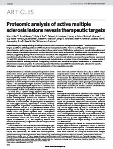
factorization of a dense matrix is representative of many dense linear algebra computations, such as factorization, Cholesky factorization, and eigenvalue methods. Dense LU factorization can be performed efficiently if the dense n2 nmatrix A is divided into an N 2Narray of B2Bblocks, (n= NB). The pseudocode in Figure 6(a), expressed in terms of these blocks, shows the most important steps in the computation. The dominant computation is Step 6, which is simply a dense matrix multiplication of two blocks. The parallel computation corresponding to a single K iteration in the above pseudo-code is shown symbolically in Figure 6(b). Two details are important for reducing interprocessor communication and thus LU
QR
Diagonal Block
Perimeter Blocks
Interior Block indicate flow of data toward blocks to be updated
Blocked Dense LU Factorization 1. For k=0 to N do 2. Factor diagonal block A kk 3. Compute values for all perimeter blocks in column k and row k 4. For j=k+1 to N do 5. For i=k+1 to N do 6. A ij = A ij − A ik* A kj
A kk Grid of Processors (cookie cutter)
/* Update interior blocks using corresponding perimeter blocks */
P6
P7
P8
P3
P4
P5
P0
P1
P2
(b) Pictorial Representation
(a) Algorithm Steps
Figure 6: Blocked Dense LU Factorization. obtaining high performance. First, the blocks of the matrix are assigned to processors using a 2-D scatter 9
decomposition. That is, the processors are thought of as a P 2 Qgrid, and block (I ; J ) in the matrix is assigned to processor (I mod P; J mod Q ). A simple 3 2 3 processor example is shown in Figure 6(b). Second, the matrix multiplication in Step 6 above is performed by the processor that owns the destination block AI ;J . The block size Bis chosen to be large enough to keep the cache miss rate low, and small enough to reduce the time spent in the less parallel parts of the computation (Steps 2 and 3) and to maintain good load balance in Step 6. Relatively small block sizes (B=8 or B=16) strike a good balance. A natural way to code LU factorization of a 2-D matrix in a shared address space is to use a 2-D array to represent the matrix. Since blocks are allocated in a scattered decomposition, and a block is not contiguous in the address space in a 2-D array, this makes it very difficult to allocate blocks in the local memories of the processors that own them, and causes false-sharing problems with long cache lines. This is a problem for the load-store model, but causes even greater complications for block transfer since memory allocation problems and false sharing imply that global coherence is required for correctness (see Section 3). This is both complex to provide and slows block transfer substantially. The solution is to ensure that blocks assigned to a processor are allocated locally and contiguously by using a 4-D array (with the first two dimensions specifying the block number in the 2-D grid of blocks, and the next two specifying the element in the block). We use such a structure in the versions that follow.
Execution Time
���
| 2
| 4
| | | | 8 16 32 64 Number of Processors
|
�� �
���
80.0 60.0 40.0 20.0
0.0 | 1
|
|
0.0 | 1
��
100.0 �
|
� �
120.0
|
|
50.0
� ��
140.0
|
|
��
100.0 �
��
�
�
Single Buffer versus No Replication
� ��
�� �
� ��
� � �
|
|
150.0
Base LS 32B Lines 64B Lines 128B Lines
|
|
200.0
� � �
|
250.0
� � �
|
300.0
|
Execution Time
Receiver-initiated load-store: We examine three versions with different degrees of replication in main memory: (i) the receiver simply fetches data on demand and relies on the cache for replication, (ii) the receiver has one block-sized replication buffer in which it explicitly replicates the important remote block that it is currently using, and (iii) the receiver replicates all blocks that it receives during a given step (or iteration of the outermost, K, loop). Figure 7 compares the schemes, using the no replication case as the base. Replicating a single block is worse than not replicating for all numbers of processors, and particularly so for larger numbers, since the cache keeps the miss rate to this block very low. Explicit replication of all communicated (perimeter, see Figure 6(b)) blocks helps when each processor has enough interior blocks so that it reuses the perimeter blocks several times. Otherwise, the overhead of replication hurts performance. Thus, replication helps only for very small numbers of processors for our small problem, and the number of processors up to which it helps increases with problem size (as we have verified through limited simulations with a 512-by-512 matrix). However, the situation in which replicated blocks are reused a lot is one in which the number of blocks per processor is high and the communication to computation ratio therefore low, which reduces the performance advantages of explicit replication. Note that the active working set for LU factorization is very small and does not depend on problem size or number of processors (only on block size B), so that the benefits of explicit replication would be further reduced with larger caches than the 8KB cache we use. However, since the performance differences are not large at small number of processors, we use no replication as our base case in comparing with block transfer.
| 2
| 4
���
� � �
���
� �
�
Base LS 32B Lines 64B Lines 128B Lines
| | | | 8 16 32 64 Number of Processors
Full Replication versus No Replication
Figure 7: LU: Comparison of Various Replication Strategies (256x256 Matrix, B=16, 8KB Cache) Sender-initiated block transfer: Since only the diagonal block and perimeter blocks (see Figure 6(b)) within a step are replicated, the storage overhead for replication is not high and there is no advantage to receiverinitiated block transfer. In sender-initiated block transfer, the processor that updates the diagonal block in a 10
Execution Time
| | | | 8 16 32 64 Number of Processors
80.0 60.0 40.0
20.0 | 1
|
| 4
Base LS BT, 128B Lines BT, 64B Lines BT, 32B Lines
��
100.0 �
|
| 2
� � �
���
|
|
20.0 | 1
� ��
No Broadcast
�� �
�� �
|
|
40.0
� ��
� � �
|
60.0
�� �
|
80.0
�� �
120.0
|
|
��
100.0 �
���
|
120.0
|
Execution Time
step sends a copy of the block to all the processors that own perimeter blocks. When a processor updates a perimeter block it owns, it sends that block to all processors that own interior blocks which need that block, and proceeds to update the next perimeter block it owns. Having sent all its perimeter blocks, it barriers until all block transfers have been done before updating its interior blocks. Thus, this scheme has all the replication that could possibly be useful, and overlaps computation and communication in processing the perimeter blocks. The main limitation on the effectiveness of masking communication with overlap is the relatively small amount of time it takes for a processor to update all its perimeter blocks compared to the amount of time taken to communicate all blocks (note also that processors that don’t own perimeter blocks are completely idle during this phase). In general, as in FFT there is not enough opportunity to fill the communication time with independent computation. All communication latency therefore cannot be hidden. Contention between block transfer and load-store accesses is very small in this application. The left graph in Figure 8 compares the performance of the block transfer scheme to that of the receiver-initiated load-store scheme with no explicit replication. Once again, there is a sweet spot for block transfer, beyond which the overheads of a processor doing many simultaneous block transfers dominate and little is gained from the replication. This sweet spot moves to a larger number of processors as the matrix size is increased. The effectiveness of block transfer also diminishes with increasing cache line size, as we expect since a block is contiguous in virtual memory.
� ��
� � �
| 2
| 4
� ��
� � �
� ��
� ��
LS BT, 128B Lines BT, 64B Lines BT, 32B Lines
| | | | 8 16 32 64 Number of Processors Broadcast
Figure 8: LU: Comparison of BT Communication Methods versus LS No Replication (256x256 Matrix, B=16, 8KB Cache) With a regular scattered decomposition, every processor sends blocks only to other processors in its row or column of the mesh. This suggests that support for broadcasting block transfers to all nodes in the same row (a row broadcast), the same column (a column broadcast), and the same row and column (an rc broadcast, for diagonal blocks) may be beneficial 5 . Broadcast reduces the number of block transfers a processor is p simultaneously involved in by a factor of p. This reduces overhead and contention at the directory controller, thus reducing communication costs and making it easier for the overlapped computation to fill the reduced block transfer time. The right hand graph in Figure 8 shows that broadcast improves performance substantially as the number of processors (p) increases. Overall, block transfer does not have as large an effect on the parallel performance of dense LU factorization on our base architecture as one might initially expect (we shall see how this changes with architectural parameters in Section 6). The main reason for this is that it is difficult to find a good sweet spot; that is, a ratio of problem size to number of processors such that the communication to computation ratio is high enough for block transfer to have substantial gains, yet the number of blocks per processor is high enough that load imbalances don’t take over as the dominant effect limiting performance. The communication to computation ratio is much larger when similar direct factorization methods are applied to sparse rather than dense matrices, so we examine blocked sparse Cholesky factorization next. 5 To accomplish a row or column broadcast, processors which are not originating the broadcast notify their directory controllers that incoming data corresponding to a broadcast message identifier must be forwarded to the next processor in the row or column. A node can be involved in multiple broadcasts at the same time. Note that a broadcast to all nodes in the system can easily be constructed from a row broadcast followed by column broadcasts from the row broadcast receivers.
11
5.3
Blocked Sparse Cholesky Factorization
Blocked sparse Cholesky factorization, which is used in a variety of applications including finite element methods and circuit simulation methods, has a similar structure and partitioning to blocked dense LU factorization. However, it operates on sparse matrices. This has two important consequences for our purposes: (i) the communication to computation ratio for a given data set size (including only nonzeroes in the sparse case) is about a factor of 10 larger in the sparse case, and (ii) the algorithm is not globally synchronized between steps and phases like dense LU factorization, which means that the amount of replication that is useful at any given time is not as well-bounded. When a processor computes an update to a block and thus makes it ready, it sends a notification for that block to all processors in that row/column that need the block. At the receiving end, a processor’s control flow is essentially as follows. The processor has an input queue of ready notifications that other processors have sent to it. It repeatedly picks a notification off the queue, and for each notification does the following: � Checks an auxiliary data structure to see which of the other “companion” source blocks that this block collaborates with—to modify a local destination block—have already been specified as ready. � If some companion blocks’ notifications have not been received, records in the auxiliary data structure that this block’s notification has been received. � For the companions that are available, performs the modifications. � When all modifications to a local block have been done, sends out ready notifications for that block. We use the benchmark matrix BCSTTK15 from the Boeing-Harwell suite for our sparse Cholesky experiments, since this matrix is small enough to simulate but large enough to be realistic. We use a 16KB cache, since this fits the important working set for a block-block update with our block size B=32. Receiver-initiated load-store: When a processor takes a notification for a nonlocal block off the queue, it has two options. First, it could simply fetch the new block, perform all modifications with it and then throw it away. In this case, if some block notification that arrives later needs this block as a companion, this block will have to be referenced remotely again. The other option is to replicate nonlocal blocks locally when they are referenced, and then free them when they are no longer needed (when all modifications from that source column of blocks have arrived). We find that replication does not help much for this matrix, and in fact hurts a little at larger numbers of processors, since the benefits of reduced communication are small and the overhead of dynamic memory management needed for replication dominate (even though this is user-level memory management, without system calls). One reason that the benefits of replication are small is that a ready block is immediately used to update all blocks for which its companion is also ready. Blocks that arrive after several of their companions are therefore not very useful to replicate, since they will not be reused much later. Receiver-initiated block transfer: For two reasons, sender-initiated block transfer is actually not as appropriate as receiver-initiated for sparse Cholesky factorization. First, since the amount of replication is not well-bounded, and since the sender sends blocks when they are ready—not when the receiver needs them— sender-initiated transfer can lead to too much replication. Second, the order in which the sender may send blocks to different receivers may not match the order in which receivers need to use them, which can lead to worse performance at the receivers. Receiver-initiated block transfer is therefore preferable to sender-initiated, even though it incurs communication latency the first time a block is referenced. In the simplest form of receiver-initiated block transfer, the receiver simply sends request messages to the directory controller of the block’s owner, which then transfers the block to it. The receiver has the option of keeping only a single, block-sized receive buffer, in which case the block is not kept around after it is used, or of replicating all received blocks in local memory until they are no longer useful (just as in the load-store case). The former option provides fast data transfer but not replication, while the latter provides both. These options reduce communication costs, but cannot hide them since they do not overlap computation with communication. Overlap can be provided by prefetching through “double-buffering”. Every time a processor goes to its input queue, it issues a block transfer request for the next block on the queue if there is one. Thus, when it actually picks that next block off the queue on its next queue access, it should find that block already arrived and can issue a prefetch for the next one. If the block hasn’t arrived yet, it waits for the block and, if possible, issues another prefetch. This scheme requires space for two blocks in the input buffer, one of which is currently being worked on and the other which is being prefetched (hence the name double-buffering). Full replication may or may not be coupled with this scheme, as before. 12
| 2
| 4
| | | | 8 16 32 64 Number of Processors
80.0 60.0 40.0 20.0
0.0 | 1
|
|
0.0 | 1
��
100.0 �
|
LS Copy, 128B Lines Copy, 64B Lines Copy, 32B Lines
120.0
|
Execution Time
�� �
|
� � �
�� �
BT No Buffering
�� �
�� �
|
Execution Time
� ��
|
20.0
|
40.0
� ��
� � �
|
60.0
�� �
|
80.0
�� �
|
|
��
100.0 �
|
|
120.0
� ��
� � �
| 2
| 4
� ��
� � �
� ��
�� �
LS BT, 128B Lines BT, 64B Lines BT, 32B Lines
| | | | 8 16 32 64 Number of Processors
BT Double Buffering
Figure 9: Cholesky: Comparison of BT Buffering Strategies versus LS No Buffering (TK15, B=32, 16KB Cache) We examine three schemes for block transfer: the single buffer with no replication (only gets fast data transfer), double-buffering with no replication (gets fast data transfer and overlap) and double-buffering with replication (gets all three). Results for the cases without replication are shown in Figure 9. While the fast transfer helps to reduce communication costs, we find that overlap through double-buffering does not help much (the improvement is only noticeable at 32 processors). There are several reasons for this. First, we find that only 30-40% of the time does a processor find something on the queue to issue a prefetch for. This, combined with the fact that often the prefetch might not have returned by the time the processor queries the queue again, results in prefetching reducing the time spent waiting for communication by only a few percent. Since communication time is not a very large fraction of runtime in our base architecture, particularly with long cache lines, this translates to only a couple of percent improvement in overall time in the best case for prefetching. Overlap through prefetching does increase the contention at the directory controllers between block transfer and memory accesses; however, the effects of this contention are once again very small. The sweet spot for prefetching with this matrix is at 32 processors, which is also the sweet spot for the fast data transfer effect of block transfer. Both fast data transfer and overlap through prefetching are likely to have a larger impact with a faster processor for the same network, since communication costs then are relatively higher. We shall examine this in Section 6. As in the load-store case, dynamic memory management for replication in main memory hurts performance significantly with block transfer as well.
5.4
Ocean Simulation
The ocean simulation studies large-scale ocean movements based on eddy and boundary currents. It is an enhanced version of the Ocean application in the SPLASH application suite, a description of which can be found in [11]. The major differences between this version and the SPLASH version are: (i) It is written in C rather than FORTRAN; (ii) it partitions the grids into squarish subgrids rather than strips of columns to improve the communication to computation ratio; (iii) it uses dynamically allocated four-dimensional arrays designed to allow appropriate data distribution and reduce false sharing; and (iv) it uses a Red-Black Gauss-Seidel Multigrid technique to solve the elliptic equations associated with the problem, whereas the SPLASH version utilizes a relaxed Gauss-Seidel SOR solver. The multigrid solver is much more efficient and scalable to large problems than SOR. A lot of the execution time of the application is spent in the multigrid solver. The multigrid solver performs near-neighbor sweeps on a hierarchy of grids rather than a single grid as in SOR. At every grid level, a processor’s partition is maintained as a contiguous subgrid padded with a border to store communicated data. This border replication is done not for reuse (since there is almost none that a cache wouldn’t exploit) but for programming ease. Since borders are sent as soon as they are computed, communication may be overlapped with computation to a limited extent. The communication at any grid level is proportional to the perimeter of a processor’s partition, and computation is proportional to the partition area. This means that communication to computation ratios become larger at coarser levels of the grid hierarchy. While this appears to be an added 13
120.0
|
��
100.0 �
|
80.0
� ��
���
|
60.0
|
40.0
|
20.0
|
Execution Time
advantage for block transfer, coarser levels have smaller partition borders and hence smaller block transfer messages. It is therefore difficult to find a sweet spot for block transfer. Also, other parts of the application than the multigrid solver do not have nearly so much communication, so there is not much to be gained by block transfer at all, as the results in Figure 10 demonstrate. Regular-grid near-neighbor iteration problems such as Ocean may improve from block transfer for much larger communication latencies and overheads, but not much for those that are realistic in tightly-coupled multiprocessors.
|
0.0 | 1
���
� � �
| 2
| 4
�� �
� � �
�� �
��
�
LS BT, 32B Lines BT, 64B Lines BT, 128B Lines
| | | | 8 16 32 64 Number of Processors
130x130 Grid, 8K Cache
Figure 10: Ocean: Comparison of BT versus LS
5.5
Radix Sort
The radix sort kernel also has a wide range of applications, including database management systems and aerospace applications (it is one of the NAS kernels [5]). It is interesting from our viewpoint because it requires the movement of large amounts of data (keys) from one processor to another during each phase of the computation, and hence appears to be a likely candidate for block transfer. Our radix sort is based on that described in [7], and sorts integer keys. If the input keys have s radix-r digits, the sort makes s passes starting from the least significant digit. Each pass sorts the keys according to the corresponding digit. For each digit, a processor performs the following steps: 1. Iterate over all local keys and create a local histogram of the number of keys per value of the current digit. 2. Accumulate the local histogram into a global histogram over all processors. 3. Iterate over all local keys again and, based on local and global histograms, write the permuted keys into the appropriate locations of an n-key array so that it is stably sorted by that digit. This n-key array is then the input for the next pass. Interprocessor communication is involved in Steps 2 and 3, with the potential for block transfer being in Step 3. The communication in step 3 is a sender-determined permutation, so that receiver-initiated communication does not make sense in either the load-store or block transfer paradigms. In the block transfer case, when a processor iterates over its keys in step 3, it does not write them directly into the new n-key array but rather uses the local histogram to write them into a locally sorted (by that digit) np -key array. The processor then uses the global histogram to determine whom to send keys to and where to put them in the destination processor’s np -sized part of the new n-key array, and block transfers the keys (digit value by digit value) to the appropriate processor(s). A key issue in the performance of radix sort is the choice of radix size. A larger radix implies less digits and hence fewer passes through the algorithm. However, a larger radix also implies a larger histogram and hence larger cache requirements. The optimal radix size is empirically determined. In the load-store model, the number of passes and cache performance are the only constraints on how large the radix should be. In the block transfer model, there is an additional constraint. Since the block transfers are done digit value by digit value, a larger radix implies that the n=p local keys will be divided into more transfers so that each transfer will be smaller. The unevenness of the key distribution exacerbates this effect. Results for our base problem 14
�
� | 2
�
�
| 4
Execution Time
Execution Time
�
� �
�
LS, 32B Lines, Radix = 16 BT, 32B Lines, Radix = 32
| | | | 8 16 32 64 Number of Processors 2KB Cache
4096.0 � 2048.0 1024.0 512.0 256.0 128.0
64.0 32.0 16.0 8.0 4.0 2.0 1.0 | 1
| | | | | | | | | | | | |
| | | | | | | | | | | | |
4096.0 � 2048.0 1024.0 512.0 256.0 128.0
64.0 32.0 16.0 8.0 4.0 2.0 1.0 | 1
�
�
� | 2
�
�
| 4
�
�
�
LS, 128B Lines, Radix = 32 BT, 128B Lines, Radix = 32
| | | | 8 16 32 64 Number of Processors 16KB Cache
Figure 11: Radix: Comparison of Fastest BT Sort versus Fastest LS Sort (65,536 Integer Keys) using two different cache sizes are shown in Figure 11. At the smaller cache size, the number of keys per processor is much larger than the cache size, while at the larger number the keys are expected to fit in the cache for the larger numbers of processors. The performance trends of radix sort are not nearly as clean as in the other applications. For this reason, rather than compare the two versions for each number of processors, Figure 11 compares the best BT sort at each number of processors to the single best sorting time obtained in the load-store case (which is at 32 processors). We see that the optimal radix changes with cache size for the load-store version, but not for the block transfer version. Although radix sort seems like an application that is amenable to block transfer since it needs to communicate almost the entire data set, the block transfer version does not perform as well for two reasons: (i) the small messages problem mentioned earlier, and (ii) the fact that communication is done through writes in the LS version allows a fair amount of the communication latency to be hidden even with realistic write buffers. Since the keys are integers, several of them fit on a cache line in the LS version, and the writes that generate communication are mostly to consecutive integers in the destination array (which makes write buffers perform well). A problem configuration that gives block transfer significant advantages will require a very large number of keys per processor and the same optimal radix for the BT and LS schemes. We will experiment more with this in the future.
6 Varying Architectural Parameters Since block transfer essentially helps reduce and hide communication costs, its effectiveness is a strong function of such factors as the communication latency relative to processor speed and local memory access time, network bandwidth, and the computational power. So far, we have examined results with a single set of machine parameters (varying only the problem size, number of processors and cache line size). In this section, we examine the effects of two critical variations. First, we look at what happens when the processing speed and local memory access costs stay the same, but the network latency changes (with network bandwidth staying the same). Second, we keep the network and memory system constant but use a much faster processor.
6.1
Varying Network Latency
In our base architecture, the latency for a one-hop remote miss was three times as large as that for a local miss. Even for tightly-coupled cache-coherent machines, the trend for remote to local miss latencies could go in two directions. Some believe that there is substantial unexploited scope in improving communication networks relative to local access, so that an assumption of a two to one ratio between one-hop remote and local misses is likely, while others believe that communication is likely to become even more expensive. We therefore experiment with both options. Higher-latency communication is also more representative of systems in which communication is not as closely integrated into the processing nodes, such as message-passing machines (and perhaps networks of workstations), particularly as the latencies in these systems continue to be reduced. 15
| 4
Execution Time
LS BT, 128B Lines BT, 64B Lines BT, 32B Lines
| | | | 8 16 32 64 Number of Processors
��
100.0 � 80.0 60.0 40.0 20.0
0.0 | 1
|
|
| 2
���
|
|
20.0 | 1
� � �
���
|
|
40.0
� � �
���
|
60.0
���
Faster Network
���
|
���
|
80.0
� � �
120.0
|
|
��
100.0 �
|
120.0
|
Execution Time
To simulate a longer-latency network, we changed the “message latency between adjacent nodes” in Table 2 from 5 cycles to 20 cycles. Note that we do not change the network bandwidth for block transfer. To simulate a faster network with 2 to 1 remote to local miss cost however, we have to increase the network speed by a factor of 4.
���
�� �
� � �
| 2
| 4
�� � �� � � � �
LS � BT, 128B Lines � BT, 64B Lines � BT, 32B Lines
| | | | 8 16 32 64 Number of Processors
Slower Network
Figure 12: FFT: Impact of Varying Network Speed (65,536 Complex Reals, 8KB Cache; also compare with base architecture results in Figure 5) Our general results are as follows. For applications in which the communication to computation ratio is high (such as FFT), changing the network latency has a strong impact on the relative advantage of block transfer. Figure 12 shows the results for FFT corresponding to the larger problem size in Figure 5. The main reason for improved relative performance with the longer-latency network is fast pipelined transfer of data: In block transfer, pipelining of the transfer implies that the increased communication latency is not multiplied by the number of cache lines communicated, as it is in the load-store case. Thus, the achieved communication bandwidth for block transfer essentially stays the same, while the achieved communication bandwidth for load-store remote-read communication decreases by a factor equal to the increase in remote read latency. The average number of network hops in the communication grows with the number of processors in the FFT (since communication is all-to-all), so that increasing the hop latency from 5 to 20 cycles has a substantial impact on average communication latency. This also causes the relative impact of block transfer to improve more with larger numbers of processors compared to the original and faster network. Finally, the curves for different line sizes in the figures move further apart for slower networks, since there are more cache misses for smaller line sizes and each incurs the full communication latency in the load-store case, making block transfer all the more important. In cases where the communication to computation ratio is low (or other factors like load imbalance dominate), such as LU and to a lesser extent Cholesky, the changes in network latency do not affect the relative performance of the block transfer and load-store versions nearly as much. LU and Cholesky also have the property that the number of network hops traversed by the average miss is much smaller than in FFT, so the latency increases are not as marked. This last effect is further accentuated in Ocean, where even the larger latency does not allow block transfer to help performance very much.
6.2
Changing Processor Speed
Our other variation is to examine the effect of having processor speeds increase much faster than memory and network speeds, with the latter two staying the same relative to each other. In particular, we show results for processors that have peak performance a factor of four larger. Using a faster processor mostly helps block transfer in those cases that have a relatively low communication to computation ratio (such as LU and Cholesky, see Figure 13). LU is a striking example. The much faster processor reduces the local computational phases of LU substantially (despite the relatively much higher local memory access cost) since LU uses its cache very effectively for local computation. This means that communication costs are much more important now, and the improvements due to block transfer a lot more marked. Replication is not the issue that helps (since local access costs are the same relative to communication 16
| 4
Execution Time
Execution Time
| | | | 8 16 32 64 Number of Processors
80.0 60.0 40.0 20.0
0.0 | 1
|
|
| 2
��
100.0 �
|
|
20.0 | 1
� � �
� � � � � � � � �
LS � BT, 128B Lines � BT, 64B Lines � BT, 32B Lines
|
|
40.0
� � �
|
60.0
� � �
LU (BT with Broadcast)
���
���
���
|
|
80.0
�� �
|
|
��
100.0 �
120.0
|
|
120.0
� � � | 2
| 4
�� �
� � �
���
���
LS BT, 128B Lines BT, 64B Lines BT, 32B Lines
| | | | 8 16 32 64 Number of Processors
Cholesky (BT with Double Buffering)
Figure 13: Impact of Varying Processor Speed on LU and Cholesky (compare with base architecture results in Figures 8 and 9, respectively). costs—only the processor has become faster); nor is overlap, since the faster processing of already overlapped computation does not help at all, and it is more difficult to fill communication time with computation. For applications with a high communication to computation ratio, making the computation go a lot faster does not help the relative performance of block transfer nearly as much (although it does help by a few percent). Once again, the absolute communication costs are about the same, and overlap doesn’t get any better. One alternative that we do not discuss in detail due to space limitations is to alter algorithms to account for increased processor speed. In [2], the author describes a method known as the dynamic block scheme for roots of unity, which allows the processor to dynamically compute roots of unity values based on a small subset that can be stored in the processor cache. By dynamically computing desired values, memory accesses to a statically computed set of all values are eliminated. This in turn eliminates interruptions to any block transfers that are in progress, allowing them to complete more quickly. Our results show that for the faster processor, the dynamic block scheme increases block transfer performance marginally over the statically computed methods assumed for the base architectural parameter set.
7 Discussion and Conclusions We have studied the performance benefits of using a block transfer facility on top of cache-coherent shared address space multiprocessors. In the introduction to the paper, we set out to address three questions: (i) how useful is block transfer, and how does its utility vary with problem size, machine size and machine parameters, (ii) what special features are useful to provide in a block transfer engine, and (iii) does one have to change an algorithm significantly to achieve good performance with block transfer. Let us now summarize our answers to these questions. We leave performance to the end since it is the most involved discussion. In terms of block transfer facilities, we found flexibility to be fairly important. While some of the applications required bulk movement of only data that were contiguous in virtual memory, others could make good use of more sophisticated features. These features include the ability to specify different fixed strides at the source and destination, and also the ability to specify a different but constant number of elements at each stride point. While these two features can be hardwired into a controller, the FFT was greatly helped by the ability of the block transfer controller to do a blocked transpose, which clearly requires a programmable controller. A facility to broadcast block transfers (at least along a row or a column) was also very useful in LU factorization, which again could easily be done in software with a programmable controller. Finally, keeping block transfer data globally coherent was not found to be needed in our applications (local coherence at source and destination sufficed), but the use of less sophisticated and more natural data structures would require global coherence due to false-sharing (see Section 5.2 for an example). The FFT was the only computation that needed algorithmic changes to exploit block transfer well. These changes include using subpartitioning to overlap communication with computation, and the dynamic computation of the roots of unity to reduce data accesses when processing speeds become much faster than the 17
memory and communication system. Radix sort required a temporary data structure to collect the data to be block transferred in, since the transfer couldn’t be done directly from the source to destination key arrays. The other cases were conceptually straightforward extensions of the best load-store algorithms. Overall, block transfer did not really help performance quite as much as we initially thought it would. There are several reasons for this. First, the fraction of execution time spent in communication that is amenable to block transfer is often not very high. This is true for some of the computational kernels we have looked at, and is likely to be even more true for real applications that use these kernels. Second, even though block transfer often greatly reduces the communication costs, we were unable to overlap enough of the remaining communication with independent computation. This problem becomes more severe as processor speed increases relative to communication bandwidth in which case reducing communication costs is important, and is fundamentally limited by the dependence structure of the computation. Third, long cache lines often capture much of the benefit of block transfer. Long cache lines may have the disadvantage of false sharing, both in general as well as for block transfer through partially written cache lines. In the examples we have seen, however, data structures that can be block transferred can also be quite easily structured to not suffer much false sharing, particularly when messages are large enough for block transfer to be useful in the first place. The final reason is a scaling argument. We have seen that block transfer usually has a sweet spot in its relationship between data set per processor and number of processors. If the number of processors is increased beyond the sweet spot for the same data set size, the communication to computation ratio increases, but the message size is reduced so that block transfer is less useful. Under memory-constrained scaling, the communication to computation ratio is often kept constant. In some cases (Ocean, LU), the message size also stays fixed and the number of block transfers that a processor is involved in at a time does not increase, so that the performance advantages of block transfer persevere. In other cases (FFT, radix sort), however, the message size is inversely proportional to the number of processors, so that as message sizes decrease, a processor is involved in more block transfers at a time, and the advantages of block transfer diminish. As discussed in Section 5.1, the most realistic scaling model for applications is time-constrained scaling, in which case the data set size does not grow as quickly as the number of processors. The communication to computation ratio gets larger but the message size becomes smaller in all cases (and the number of simultaneous block transfers still increases in FFT and radix sort), so that the effectiveness of block transfer diminishes under time-constrained scaling starting from the sweet spot. Of course, how the advantages of block transfer scale depends on where the starting point is relative to the sweet spot. Most of the advantages we obtain from block transfer in these applications are due to fast data transfer. Replication of important data structures in main memory was not useful in three applications (Ocean, FFT, and radix sort) and its benefits did not outweigh its costs by much in others (LU and Cholesky) 6 . Overlap of block communication with computation was not very useful for Ocean and radix sort, had a small effect for LU and Cholesky, and had a relatively important effect for FFT (although the effect diminishes as processor speeds increase relative to communication speeds). Contention at the controller (and hence memory) between the block transfer and load-store accesses was in all cases not a significant problem compared to other sources of performance loss. Software controlled prefetching in a load-store model is an alternative way to hide communication costs. It is quite successful when communication is very predictable from the receiver’s perspective. Among our applications, prefetching is not of much use in radix sort, since the communication is fundamentally senderdetermined. And in cases like LU and Cholesky, the compiler can only easily determine what to prefetch at the beginning of a task (such as a block-block update), which may not be very useful when the communication latency is very high relative to the computation speed and hence the time it takes to compute the task (i.e. the startup cost of the prefetching pipeline dominates and the steady state is very short). Block transfer allows us to overlap communication and computation at a much coarser grain (across tasks), and to schedule task computation and communication more explicitly, and thus hides latencies more effectively. Prefetching is also limited by the number of outstanding prefetches allowed. We would like to experiment quantitatively with prefetching in the future, as well as with the impact of including contention in the network itself. 6 Automatic replication is, however, often useful in compensating for programmer carelessness (or easing the programmer’s task) by replicating small, seemingly insignificant shared data structures and variables (see Section 2). For this and various other reasons—such as avoiding the complications of explicit data placement, and for robustness in the presence of process migration and multiprogramming—a system that provides automatic replication and migration of data in addition to the replication that comes with block transfer (such as a COMA machine with a block transfer facility) might be a nice design point.
18
Overall, the computations that benefited substantially from block transfer with our base architectural parameters are FFT and Cholesky factorization, and to a lesser extent LU factorization (the benefits for the latter two would be significantly greater if we used faster processors in the base architecture). Regulargrid applications such as Ocean are not helped much by block transfer, since either the communication to computation ratio is not high enough or the messages are too small. Dense matrix factorizations like LU also have the problem that at the ratio of problem size to number of processors where communication becomes important, load imbalance takes over as the dominant source of performance loss. In radix sort, the messages are too short unless the number of keys per processor is huge relative to the number of processors. In addition, the natural load-store version works very well with write buffers. We also examined the effects of varying network and processor speeds on the advantages of block transfer relative to load-store communication. Generally, we found network latency to have a greater impact on the advantages of block transfer in applications with a high computation to communication ratio (such as FFT), and increased processor speed (for the same memory system and network bandwidth) to improve the advantages for applications with relatively low communication to computation ratios (such as LU). Thus, increased processor speed did not have a large impact for FFT, and increased latency did not for LU. Other Applications: We also looked at other applications from the viewpoint of improving performance through block transfer. Many application classes (such as N-body problems) have the property that the communication to computation ratios are low, working sets are small, and the data sharing is very fine-grained, so that standard cache coherence works very well. Using block transfer would require a complete restructuring of some of these algorithms, and would probably hurt performance or at least not help significantly. A case where block transfer has been said to be useful is in manipulating global task queues in dynamically scheduled computations [6]. We looked at several real applications that use dynamic task-queue scheduling. In most cases, the scheduling can be managed with distributed queues such that the frequency of accessing nonlocal queues is small. Also, the time spent manipulating queues is only a very small fraction of the time spent doing useful computation, so that block transfer is unlikely to help significantly. We believe that the computations we have chosen are good candidates, and we are not aware of other candidates that might benefit more.
Acknowledgements This work was supported by the Defense Advanced Research Projects Agency under contract number N0003991-C-0138. Steven Woo is also supported by a Hughes Aircraft Company Doctoral Student Fellowship. The authors are grateful for the support of these organizations.
References [1] Anant Agarwal, Beng-Hong Lim, David Kranz, and John Kubiatowicz. April: A processor architecture for multiprocessing. In Proceedings of the 17th Annual International Symposium on Computer Architecture, pages 104–114, May 1990. [2] David H. Bailey. FFTs in external or hierarchical memory. Journal of Supercomputing, 4(1):23–35, March 1990. [3] Brian N. Bershad, Matthew J. Zekauskas, and Wayne A. Sawdon. The Midway distributed shared memory system. In Proceedings of COMPCON’93, February 1993. [4] Sandhya Dwarkadas, Pete Keleher, Alan Cox, and Willy Zwaenepoel. An evaluation of software distributed shared memory for next-generation processors and networks. In Proceedings of the 20th Annual International Symposium on Computer Architecture, May 1993. [5] David H. Bailey et al. The NAS parallel benchmarks. International Journal of Supercomputer Applications, 5(3):63–73, Fall 1991. [6] David Kranz et al. Integrating message-passing and shared-memory: Early experience. In Principles and Practice of Parallel Programming, pages 54–63, May 1993. 19
[7] Guy E. Blelloch et al. A comparison of sorting algorithms for the Connection Machine CM-2. In Symposium on Parallel Algorithms and Architectures, pages 3–16, July 1991. [8] Stephen R. Goldschmidt and Helen Davis. Tango introduction and tutorial. Technical Report CSL-TR90-410, Stanford University, 1990. [9] Dan Lenoski, James Laudon, Kourosh Gharachorloo, Anoop Gupta, and John Hennessy. The directorybased cache coherence protocol for the DASH multiprocessor. In Proceedings of the 17th Annual International Symposium on Computer Architecture, pages 148–159, May 1990. [10] Jaswinder Pal Singh, John L. Hennessy, and Anoop Gupta. Scaling parallel programs for multiprocessors: Methodology and examples. IEEE Computer, 26(7):42–50, July 1993. [11] Jaswinder Pal Singh, Wolf-Dietrich Weber, and Anoop Gupta. SPLASH: Stanford parallel applications for shared memory. Computer Architecture News, 20(1):5–44, March 1992. Also Stanford University Technical Report No. CSL-TR-92-526, June 1992.
20