MEASUREMENT SCIENCE REVIEW, Volume 1, Number 1, 2001
THE TEST OF THE AD CONVERTERS EMBEDDED ON TWO MICROCONTROLLERS R. Holcer, L. Michaeli, J. Šaliga Department of Electronics and Telecommunications, Technical University of Košice, Park Komenského 13, SK-04120 Košice, Slovakia, Phone (421) 95 6022853, Fax (421) 95 6323989, E-mail:
[email protected] Testing method of ADC’s implemented on microcontroller chips are descibed in the paper. The achieved results for microcontroller AT90S8535 and ADuC812 are discussed too. As a criterion of ADC precision, which allows to determine the operational condition limits, the number of effective bits has been chosen. More over, the DNL and INL measured characteristics are presented. The results are compared to some of the data brought out in vendors’ data sheets. Keywords: ADC performance testing, ADC errors and precision, microcontrollers,. 1
INTRODUCTION
Presently, the microcontrollers with analogue to digital converters (ADC) implemented on single chips and necessary analogue signal conditioning pre-processing blocks are very useful tools to design intelligent sensors. The aim of such structures is to recover the sensor's output signal as close as possible to the acquisition point in order to reduce the parasitic quantity impact. Acquired data are digitised, linearised, encoded and in the suitable format transmitted to the supervising computers which control the measuring process. Some of such microcontrollers possess general purpose voltage inputs. These inputs are sophisticated for the applications, where an additional analogue pre-processing circuit converts any output value from sensor into the ADC convenient voltage range.
2
ADC TESTING METHODS
The ADC implemented in tested microcontrollers contains a sample and hold circuit and these make possible to use dynamic testing methods in accordance with the IEEE Std. 1241 and 1057 [1,2]. The dynamic testing methods have been chosen for testing number of effective bits (ENOB) as well as for testing differential and integral non-linearity (DNL, INL). All methods enable to utilise the harmonic generator with low harmonic distortion and medium frequency stability. The total harmonic distortion (THD) of test signal can be improved by a low pass or band pass filter. For testing the ENOB the sine wave fitting test method has been chosen for various input frequencies. The medium time frequency stability of the test generator enables to approximate parameters of the harmonic signal from acquired sample data by the four parameter method [1,2]. Finally, the ENOB can be calculated from acquired and processed data. The histogram method with a sine wave input signal was used for measuring the DNL and INL. The obtained histogram was linearised by comparing to the ideal sine wave histogram and then the DNL and INL was calculated [1,2]. The Pentium based PC with National Instrument card Lab-PC-1200 was applied to control the test process. A function/arbitrary waveform generator HP33120A (Hewlett Packard) was used for generating of harmonic input signals. Moreover, a simple optional RC low pass filter was applied to improve THD at the ADC input. The filter cut-off frequency was chosen and changed in relation to the harmonic test signal frequency. Sampling frequency was given by the microcontroller program and derived from the microcontroller crystal oscillator by an internal timer, if it was needed. A microcontroller software was written, debugged and compiled in the supervising PC by the developing software tools and then the microcontroller
55
Theoretical Problems of Measurement ● R. Holcer, L. Michaeli, J. Šaliga
was programmed. The test controlling, data processing and presentation software for PC was fully developed in LabWindows/CVI programming environment (National Instruments).
3
ADuC 812 MICROCONVERTER
The ADuC812 by Analog Devices [4] is a fully integrated 12-bit data acquisition system incorporating a high performance self calibrating 8-channel ADC, dual 12-bit DACs and programmable 8 bit MCU (8052 instruction set compatible) on a single chip. The ADC conversion block provides the 8-channel mux, track/hold, on-chip reference, calibration features and A/D converter. The A/D converter consists of a conventional successiveapproximation converter based on a switched capacitor DAC. A high precision, low drift and factory calibrated 2.5V reference is given on-chip. The internal reference may be overdriven via the external VREF pin. The ADC has been designed to run at a maximum speed of 1 sample every 5µs. (i.e. 200kHz sampling rate). Single step or continuous conversion modes can be initiated in software or alternatively by applying a convert signal to the an external pin. Internal timer can also be configured to generate a repetitive trigger for ADC conversions. The ADC may be configured to operate in a DMA Mode whereby the ADC block continuously converts and captures samples to an external RAM space without any interaction from the MCU core. The ADuC812 is shipped with factory programmed calibration coefficients which are automatically downloaded to the ADC on power-up ensuring optimum ADC performance. The ADC core contains automatic end point self-calibration and system calibration options that will allow the user overwrite the factory programmed coefficients if desired and tailor the ADC transfer function to the system in which it is being used. The basic specification of ADC are referred in tab. 3.
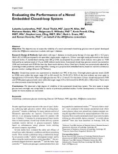
TESTING PROCESS AND EXPERIMENTAL RESULTS The test was executed on the microcontroller implemented on the evaluation board EVALADuC812QS by Analog Devices [5] with crystal frequency equal to 11.0592MHz. Input operate amplifier was disconnected and the testing signal from waveform generator was connected directly to ADC input pin of microcontroller via RC filter. The original power supply source (the board accessory) was utilized for measuring and the internal reference VREF=2.5V was used as the ADC voltage reference. The ADC was tested in all conversion modes but this paper presents only the mode with the best results - continuos DMA conversion mode by using data memory on board and MCU core in IDLE operating mode. The tab.1 and the fig.3 showed the best measured results from all setting of the acquisition time for all possible setting ADCCLK . The fig.1 Table 1. Results of ENOB test of AduC812 for and the fig.2 showed result of DNL and INL various ADCCLK. testing, where fIN=3.3Hz, ADCCLK=MCLK/8 and ADCCLK MCLK / 8 MCLK / 4 MCLK / 2 MCLK / 1 ADC used timer2 for repetitive trigger, then acq. time 2/ADCCLK 4/ADCCLK fSAMP=27,1kHz. 76800 11.24 11.27 11.25 11.28 11.24 11.22 10.81 9.89 9.39
153600 276481 526631 ENOB [bit]
11.3
11.25 11.29 11.29 11.29 11.27 10.86 9.89 9.37 9.30
8.11 8.10 8.09 8.10 8.08 8.03 7.95 7.94 7.91 7.89
10.8
5.35 5.33 5.35 5.32 5.34 5.32 5.36 5.31 5.16 5.31
ENOB[bit]
fSAMP [Hz] fIN[Hz] 11 33 110 330 1100 3300 11000 33000 66000 75000 110000 135000 260000
10.3
9.8
9.3 10 MCLK/8
100
1000
10000
fIN[Hz]
100000
MCLK/4
Figure 3. ENOB of ADuC812 for var. ADCCLK.
The sampling frequency in the last two columns are higher than specified maximal sampling frequency 200kHz. 56
MEASUREMENT SCIENCE REVIEW, Volume 1, Number 1, 2001
Figure 1. Differential non-linearity of ADuC812.
Figure 2. Integral non-linearity of ADuC812.
Without IDLE mode the ENOB is lower by about 0.3 LSB in the all conversion mode. Also an activity of internal timers causes decreasing of ENOB. For example, when the ADC was triggered by timer 2 (without DMA , without IDLE) and other internal timers were also active, maximal ENOB was 10.8 bits. The testing ADC with battery supply source had better results by about 0.2bits. Shapes of measured characteristics are identical for all conversion modes, however the absolute values depend on the disturbing factors mentioned higher.
4
AT90S8535 MICROCONTROLLER
The AT90S8535 by ATMEL [3] is a low-power CMOS 8-bit microcontroller based on the AVR RISC architecture. The AT90S8535 features a 10-bit successive approximation ADC, 8channel multiplexer and a Sample/Hold Amplifier. An external reference voltage must be applied to the AREF pin. The ADC can operate in single or free run conversion mode. In the first mode, each conversion will have to be initiated by the user. In second mode, the ADC is constantly sampling and updating the ADC data register. The ADC contains a prescaler, which divides the system clock to an acceptable ADC clock frequency. The ADC accepts input clock frequencies in the range 50 - 200 kHz. Using Free Run Mode and an ADC clock frequency of 200 kHz gives the highest sampling frequency 15.4kSps. To improve noise reduction, the vendor recommends the Sleep mode of the microcontroller, when the core activities are stopped during the AD conversion. The basic specification are referred in tab. 3.
TESTING PROCESS AND EXPERIMENTAL RESULTS The test was executed on microcontroller with crystal frequency equal to 8MHz. The testing harmonic signal from waveform generator was connected directly to ADC input pin of microcontroller via RC filter. As the external voltage reference VREF=2.5V was used integrate circuit AD680 (Analog Devices). The ADC Table 2. Results of ENOB test of AT90S8535 in free was tested in both conversion mode. The run mode for various ADCCLK. results of ENOB for ADC in free run mode ADCCLK MCLK/128 MCLK/64 MCLK/32 MCLK/16 MCLK/8 (without timer) for all possible setting fSAMP [Hz] 4808 9616 19233 38337 76935 ADCCLK are presented in the tab.2 and the fIN[Hz] ENOB [bit] fig.4. The fig.5 and the fig.6 showed result 9,41 9,33 9,39 9,44 ≤ 3.3 9,40 of DNL and INL testing, where fIN=3.3Hz, 11 9,37 9,40 9,36 8,88 9,41 ADCCLK=MCLK/32 and free run mode. 33 9,17 9,20 9,13 7,75 9,21 9,13 9,14 9,04 9,14
9,13 9,14 9,09 9,10 9,06 8,97 8,38 7,78
9,11 9,12 9,08 9,02 8,98 8,85 8,39 7,94 7,47
5,85
9,16 9,17 9,15 9,05 9,13 8,79 8,30 7,91 7,41 6,59
10 9 ENOB[bit]
100 300 1000 3000 10000 30000 60000 90000 130000 250000
8 7 6 5 1
10 M CLK /128 M CLK /16
100
1000 M CLK /64 M CLK /8
10000
100000 M CLK /32
1000000
f IN [Hz]
The ADCCLK in the last three columns are higher Figure 4. ENOB of AT90S8535 in free run mode than specified maximal 200kHz. for various ADCCLK.
57
Theoretical Problems of Measurement ● R. Holcer, L. Michaeli, J. Šaliga
Figure 6. Integral non-linearity of AT90S8535.
Figure 5. Differential non-linearity of AT90S8535.
ADC testing with supply from various power sources (power range AVCC=VCC from 2,8V to 5,5V) hasn’t indicated any influence of power source on ENOB. Even an application of battery supply source hasn’t brought any advance.
5
CONCLUSION
Table 3. Comparison table of ADC specifications.
AVDD=DVDD=AVCC=VCC =5V, VREF=2.5V The mutual comparing of ADC AduC812 AT90S8535 parameters is not easy, because the by vendor measured by vendor measured resolution of ADCs implemented on Resolution 12 Bits 10 Bits tested microcontrolers is different. ENOB 11.3 Bits 9.45 Bits Some of these parameters are INL (typ.) ±0.5 LSB ±0.2 LSB (max.) ±1.5 LSB 1.6 LSB ±0.5 LSB 1.4 LSB presented in tab.3. However these DNL (typ.) ±1 LSB ±0.2 LSB ADCs can be compared from other (max.) 1.2 LSB ±0.5 LSB 0.95 LSB point of view. Experiments with SNR 70 dB 69.7 dB 58.7 dB microconverter AduC812 confirmed high time punctuality of its triggering circuit. Also the microcontroller AT90S8535 has similar precise time triggering but only in free run mode. In repeated triggered single conversion mode controlled by any timer a triggering jitter was indicated. It depends on run-time optimisation of ADC start conversion subroutine. The experimental results from testing ADC implemented on AduC812 are most coherent to the expected error model of SAR ADC described in [4,5] than those from similar AD converter embedded on microcontroler AT90S8535. In order to avoid complicated testing stand authors developed new testing method described in the [6]. The stimulus signal of exponential shape is a new idea. The achieved results from both methods Figure 7. Differential nonlinearity of ADuC812 by exponential testing. were compared - fig.7 versus fig.1.
REFERENCES [1] IEEE Std. 1241 - 2000, "Standard for Terminology and Test Methods for Analog-to Digital Converters", Institute of Electrical and Electronics Engineers, Inc. New York, USA 2000 [2] IEEE Std. 1057 - 1994, "IEEE Standard for Digitizing Waveform Recorders", Institute of Electrical and Electronic Engineers, Inc. New York, USA 1994 [3] Preliminary Datasheet of ATMEL 8 bit AVR microcontrollers AT90S4434/AT90LS4434/AT90S8535/ AT90LS8535, Rev. 1041E–04/99, Atmel Corporation 1999. (See also http://www.atmel.com) [4] Preliminary Datasheet of Analog Devices MicroConverter ADuC812, REV. PrD Nov. /98, Analog Devices, Inc. 1998. (See also http://www.analog.com) [5] ADuC812 52PQFP Applications board user guide, Version 3.00, 30. March 1999, Analog Devices, Inc. 1999. (See also http://www.analog.com) [6] R. Holcer, L. Michaeli, "DNL ADC Testing by the Exponential Shaped Voltage", Accepted for publication for Proceedings of IMTC’2001, Budapest, Hungary, May 21-23, 2001.
58