Pre-print: Dorin, A., Geard, N. (2014) "The Practice of Agent-Based Model Visualization", Artificial Life, Vol. 20, No. 2, 1–19.
The Practice of Agent-based Model Visualization
Alan Dorin1, Nicholas Geard2
1
Faculty of Information Technology, Monash University, Clayton, Australia
2
Melbourne School of Population Health, University of Melbourne, Parkville, Australia
[email protected] (corresponding author)
[email protected]
Abstract. We discuss approaches to agent-based model visualization. Agent-based modelling has its own requirements for visualization, some shared with other forms of simulation software, and some unique to this approach. In particular, agent-based models are typified by complexity, dynamism, non-equilibrium and transient behavior, heterogeneity, and a researcher’s interest in both individual- and aggregate-level behavior. These are all traits requiring careful consideration in the design, experimentation and communication of results. In the case of all but final communication for dissemination, researchers may not make their visualizations public. Hence, the knowledge of how to visualize during these earlier stages is unavailable to the research community in a readily accessible form. Here we explore means by which all phases of agent-based modeling can benefit from visualization and we provide examples from the available literature and online sources to illustrate key stages and techniques. Keywords: agent-based model; individual-based model; virtual ecosystem; visualization
1
2
1.0
Introduction
Agent-based models (also called individual-based models) are applied in the fields of artificial life [54], ecology [25], computer graphics [41], social science [19], epidemiology [1] and in a good many other areas [5]. The modelling technique is particularly well suited to experimentation with systems where many relatively simple individuals, through local interactions, give rise to global emergent behaviour. That is, the phenomenon under study is not explicitly represented by a state variable of one agent, nor even necessarily by an aggregate variable such as a population mean. For instance, in considering an agent-based model of flocking behaviour [41], there is typically no variable, either at the individual or environmental level that represents the flock. Flocking “emerges” from the interactions of the agents as an aggregate spatio-temporal phenomenon. The property of “flockiness” may be qualitatively represented using a vector, perhaps indicating the mean of all bird headings and speeds, and somehow displaying the nearest neighbour distances etc.. But these values are no substitute for seeing the flock in action. Actually, they may give no clear indication of what results from their combination. This aspect of agent-based modelling in particular, often requires us to consider visual means1 to work with our simulations, which is not equally true for every type of simulation model. Other traits commonly found in agent-based models include complexity (in the formal sense, non-linearity and unpredictability of interactions), dynamism, non-equilibrium and transient behaviour, as well as heterogeneity of components. These features can make agent-based models difficult to grasp, a problem that can be alleviated by careful visualization, whatever the application domain.
We adopt a broad definition of visualization that encompasses areas variously referred to as model visualization, data visualization, information visualization, interactive visualization and so on. We include in our categorisation sketches, graphs, diagrams, renderings, animations etc.. Essentially we
1
Or in some cases, audible means [18], but this is outside our present scope.
Pre-print: Dorin, A., Geard, N. (2014) "The Practice of Agent-Based Model Visualization", Artificial Life, Vol. 20, No. 2, 1–19.
mean any visual representation of a model, from its conceptual structure to its dynamic behaviour, that allows a viewer to bring to bear their abilities for “visual thinking” [21].
The aim of this paper is to assist modellers with visualization during the process of developing and presenting agent-based models. Regardless of application domain, as we shall demonstrate by diverse examples, agent-based models have similar visualization requirements. We provide and discuss some well and lesser known examples from the literature. Since many agent-based modellers do not publish their visualizations or discuss the techniques they applied (these are often superfluous to the results being published while being of use during the research itself), there is a lack of information on how experienced modellers employ visualization at all stages apart from to communicate results. This forces new modellers to reinvent visualization approaches or sometimes to overlook the utility of visualization entirely, when they build their first simulations. Existing publications [9, 46] provide parallel and additional reasoning to justify the need for a sophisticated approach to visualization in the related areas of artificial evolution, complex adaptive systems and of artificial life more broadly. In this paper however, we reveal some specific techniques that beginners and more experienced agent-based modellers might apply, and demonstrate the use of visualization at all phases of agent-based modelling.
This paper does not cover how to select colours, lay out information, or draw effective graphs for agent-based modelling applications. Kornhauser et al. [32], the tutorial notes by Dorin [14] and the texts by Tufte (e.g. [51]) cover some of these ideas. Rather, we assume some knowledge of effective visual design and instead focus on how, when, why and to what this knowledge should be applied. To raise a red flag we also briefly illustrate how meaning is conveyed through aspects of a visualization design that often fall beneath the radar. Even the undertones of visualizations – the subtle devices they use and the connotations they suggest – are worthy of explicit consideration during the research process [34]. 3
4
We break research using agent-based models into sub-tasks that occur roughly in sequence, possibly iteratively, during a project. These provide different targets for visualizations as follows: 1) Simulation design – from new ideas to methodical construction 2) Software debugging and verification 3) Model validation 4) Comprehension of causes and effects within the model 5) Perception and detection of patterns in a simulation for later formal quantification 6) Communication of methods and results for dissemination Although visualization is more often associated with the later stages, we argue that it is worth considering visualization throughout the process of model design, development, use and communication. Below we explore the unique visualization needs of each stage in a project and then touch upon the importance of hidden meanings often inadvertently introduced into visualizations. We conclude the paper with some general observations.
2.0
Why, what and when to visualize?
In this section we step through each stage of agent-based modelling research listed above showing how visualization can assist in a project. The features of agent-based models most likely to require visualization are: •
Individual agent states and behaviours
•
Agent-agent interactions
•
Population aggregates (e.g. mean, standard deviation) and emergent properties
•
Environmental states and processes (e.g. physico-chemical)
•
Agent-environment interactions
Pre-print: Dorin, A., Geard, N. (2014) "The Practice of Agent-Based Model Visualization", Artificial Life, Vol. 20, No. 2, 1–19.
Some of these are straightforward, requiring standard visualization tools and techniques, others less so. We pick out a few example visualizations from these categories as we explore the stages of research from problem conception to communication of results.
2.1
Simulation design – from new ideas to methodical construction
At this, the first stage of research, visualization techniques must be fast enough to keep pace with rapid changes in ideas. A pencil sketch is great and can easily set the course for years of future work! The desire to set an idea in stone at this early stage, by working for days on a beautiful rendering or computer graphics visualization should be resisted. For instance, a scribble like Darwin’s in figure 12(a) takes a few seconds to draw, Haeckel’s corresponding figure 12(b) represents hours of work. Would you be willing to throw out an idea if you had rendered it as carefully as Haeckel’s? It is harder to be precious about a sketch, making it appropriate when new ideas are being devised.
Even sketches and simple figures can disguise and reveal assumptions made in the early stages of an idea’s development. It is certainly a good idea to critique them carefully. For instance, figure 1(a) is the kind of textbook figure, a model visualization if you like, typically employed to illustrate the relationship between an agent and its environment (e.g. see [43, p. 35]). In this representation the agent is not situated in the environment, it is only weakly coupled to it through its sensors and actuators. This coupling appears to be entirely controlled by the agent, i.e. the sensors and actuators belong to the agent, the environment can’t impact on the agent unless the agent is paying it attention. We all know this to be a shoddy representation of reality, yet by putting images such as this in popular undergraduate texts we are subtly misrepresenting the situation to our students! Still, the approach has its benefits, especially in the field of robotics where an agent’s role may be to navigate through an essentially passive world. If the world is not perceived by the roboticist to be passive, then this representation of the situation is inappropriate. This representation is probably 5
6
also inappropriate as the basis for a model in which agents and their components are expected to emerge from, and be recycled through, a chemical soup – the same soup that constitutes their environment. Arguably a lack of attention to this detail has given rise to the quandary where our evolutionary ecosystem simulations are not open-ended like those of nature [31].
Figure 1(b) is less common than (a). It positions the agent within the environment (cf. figure 9). However even this visualization of the relationship highlights the impact of the agent on the environment without making specific reference to the way in which the environment affects an agent, whether the agent senses the interaction or not. For example, UV radiation may interfere with an agent that remains blissfully unaware of this. Yet, in this diagram, no way for such an interaction to occur is represented. Figure 1(c) illustrates a significantly different and less common perspective.2 The agent is not in the environment, the agent and environment mould one another, they are coupled. If the environment perturbs the agent the agent may passively accept this perturbation (such as by absorbing a temperature change) or actively resist it (such as by attempting to maintain a constant body temperature). Whether or not the agent remains viable after the interaction depends on the exact situation, in fact, the change to the environment may be equally dire, as this image conveys by giving the two elements equal weight.
Each sub-image of Figure 1 could give rise most naturally to a unique agent-based model, possibly at the level of the data-structures and algorithms employed when it comes time to convert ideas to software, but certainly at the level of their conceptualisation. This highlights the utility of ascertaining the assumptions even a basic visualization entails, in order to see if they appropriately mesh with our understanding of the situation being modelled and our desires for its representation. This is true at all stages of research, however particular care must be taken to set off on a good foot.
2
Humberto Maturana presented a figure similar to this at Language, Emotion and Knowing: An explanation of what it
is to be human, Melbourne, Australia 23-25 August 1997. The idea is inspired by his notion of structural coupling [42].
Pre-print: Dorin, A., Geard, N. (2014) "The Practice of Agent-Based Model Visualization", Artificial Life, Vol. 20, No. 2, 1–19.
Programmers and software engineers will no doubt be familiar with the benefit of visualizing relationships between software components (e.g. using Unified Modeling Language (UML)3) before turning their ideas into hard code. Diagrams can assist dramatically in articulating the design of algorithms but it is well beyond the scope of this paper to describe this. Flow charts are also of utility in the construction of software, and of agent-based models. For instance, Tews et al [50] illustrate the flowcharts that form the basis of an ecological simulation. In this form the designer can formalise a model and its requirements for parameters such that its assumptions and relevance may be questioned before the process of moving to software commences. Once the software is written, the assumptions of a model and its parameters are essentially hidden from view, buried in what might be many tens or hundreds of thousands of lines of code. With a clearly articulated, visualized model plan, the problem of checking the software becomes one of verification – does the software correctly recreate the abstract model represented by the plan? And this is clearly distinct from whether or not the abstract model correctly represents the real world system under study. The distinction makes it much easier to conduct “good science” than if the model is never explicitly and publicly articulated. 2.2
Software debugging and verification
Once an idea has been represented in software, it must not yet be set in stone. There are the obvious bugs to iron out so that the code runs, but of course we must ascertain that the software correctly represents the model. Visualizations are of great assistance for answering questions concerning this issue. For example, do the agents’ random walks appear uniformly random? Are the different resources equally spread throughout the environment? Is the agent food appearing in the environment according to the required patchy distribution? While it may appear trivial to code something such as a uniform random distribution of resources across a space, it pays to check. The consequences of a mistake can alter the behaviour of a simulation significantly. Consider the 3
http://www.omg.org/spec/UML
7
8
difference between laying out resources on a uniform grid and across a spherical model planet (figure 2(a & b)). In the former case, each grid square has identical area. In the latter case, a common way to represent the surface is using longitudinal and latitudinal lines that meet at the poles and outline surface polygons of non-uniform area. You must then take care when adjusting the probability that a polygon sprouts a resource or the poles will have an extremely high resource density! It is hard to overlook simple errors like these when a graphical representation of the model world is rendered.
Some visualizations allow for agents in a particular user-specified state to be clearly tagged. For instance, the bee simulation [17] shown in figure 2 (a) allows the user to tag flowers by rendering over them a filled square to indicate that nectar is available and a hollow square to indicate that it has been collected. This provides visual answers to the following questions: Are the correct flowers offering rewards at the correct time? Are the rewards being collected by the right type of bee? Are the bees foraging uniformly across the space, or are spatial effects associated with proximity to edge boundaries or hive location impacting on the collection of nectar from some flowers? Answers to these basic questions act as checks for correct simulation function. In some cases, visualization can assist in solving even tricky problems. For instance, Sims explains that, “One of the most surprising [results] was probably when the evolving creatures found and exploited bugs in the physics simulator to propel themselves at totally unrealistic speeds” [20]. Agents making movements such as these, or travelling incorrectly through walls and floors due to faulty collision detection, or faking locomotion by growing very tall and toppling away from their starting location [6, foot. 3] can all be detected immediately through visualization, allowing the programmer to hunt down bugs that might otherwise go unnoticed.
2.3
Model validation
Pre-print: Dorin, A., Geard, N. (2014) "The Practice of Agent-Based Model Visualization", Artificial Life, Vol. 20, No. 2, 1–19.
After verification of the software’s technical correctness it, and the model it encapsulates, must be validated against the real system under study. Some aspects will be relatively easy to validate, for instance the production of the correct distribution of species at various trophic levels in an ecosystem can be determined using standard statistical tools. Others will be much more difficult, for instance checking that the types of relationships (e.g. predatory, symbiotic etc.) and interactions (e.g. habitat provision, exclusion etc.) appearing between agents and their abiotic environment parallel those found in real ecosystems. The topology of agent interactions is commonly represented as a tree or cyclic graph and can therefore employ any of an array of network visualization strategies from other fields (e.g. see [53] in the context of communication networks or [7] more generally). A graph is useful for representing momentary contact (such as that required to transmit a disease [2] or historical evolutionary lineages). The trees of Darwin and Haeckel (figure 12) are examples of the latter taken from attempts to illustrate real evolutionary biology, each conveys the apparently neat way in which new species are formed from common ancestry. Doolittle [13] presents an alternative view in which, at the level of the earliest and simplest (e.g. bacterial) life forms, the divisions between branches in the tree are not clear-cut. Instead, the relationships between microorganisms produce a tangle of paths, a graph, network or web, and they do not emerge from a single common ancestor but from a “community of primitive cells”.
One advantage of explicitly visualizing the relationships between agents is that some network traits are hard to quantify. For instance, network “complexity” appears to be an intuitive concept, but nutting it out in quantitative detail reveals it to be slippery [15]. In addition, the presence of key nodes, leaf nodes and a correspondence between these and the agents they represent is often of value in understanding how a set of agents generate large scale properties of the systems that support them. Ecosystem stability, resilience and other properties are tied in complex ways to biodiversity, trophic interactions and the presence of keystone species or ecosystem engineers [30]. 9
10
The relationships between these features of the network and the agent types filling these niches can be difficult to detect with analytic techniques but sometimes are even trivial for our visual sense: Which food sources are key to the stability of the food chain in figure 3? What are the likely impacts on the ecosystem if species 14 is eliminated? It is possible to get a hold on answers to questions such as these by investigating a well-laid out figure, before even testing the validity of one’s conclusions using the agent-based model that generated a network. Of course, identifying appropriate figure layouts may itself take a lot of thought and experimentation.
In validating a model we can compare two networks at a coarse level to see if they have similar structures: similar depth, breadth, proportion of leaf nodes to hubs etc.. This can tell us something about the relationship between our software simulations and the systems they are purporting to model, even before we resort to quantitative analysis using tools such as the shortest-path length or clustering coefficient. (E.g., see [7, Table 12.2].)
An agent-based model simulating the emergence of biological food-chains might be less likely to omit decomposers after their role in “closing the circuit” was made visible by examining a real food chain laid out graphically. For example, in figure 3, nodes 1, 2 and 3 represent detritus, bacteria, and fungi respectively (see [36] for details). These nodes clearly support a lot of the network. Many ecosystem simulations operate successfully without decomposers, sometimes their omission is warranted. But this should be a conscious decision made after validation of the model’s behaviour, not a case of out of sight out of mind. A visualization helps to bring things to the fore that might otherwise never enter sight.
2.4
Comprehension of causes and effects within the model
Simulation models may have many parameters for which even small tweaks can result in dramatically different outcomes. These sensitivities will eventually need to be well understood but
Pre-print: Dorin, A., Geard, N. (2014) "The Practice of Agent-Based Model Visualization", Artificial Life, Vol. 20, No. 2, 1–19.
in the first place, it is helpful to set up a simulation with easy means to adjust these and observe the results visually. A GUI enabling interactive manipulation of parameters before and during a simulation run can be of great assistance in allowing a viewer to gain a feel for how a model responds to different conditions. Grimm suggests this to be an ideal way to communicate a simulation because it enables clients or ecologists to come to grips with a finding by rapidly conducting their own controlled experiments and observing the results, without needing to delve into program code [24].4 In fact, we believe this is an effective way even for programmers to come to grips with their own simulations during development and beyond. It can potentially allow for the exploration of different scenarios within a timeframe that allows for mental comparison. Without the need to type numbers into files, save, reload parameter databases, recompile, adjust program code etc. (all activities that interrupt the mental processing required for comparison of simulation results) a researcher is free to focus on the task at hand – understanding model behaviour.
Victor [52] points out that an important benefit of interactive visualization is that it enables a viewer to move up and down the ladder of abstraction – an idea that takes on great significance when considering the emergent properties of agent-based simulations. To form intuitions about a complex system, a researcher must be able to freely move between views of concrete systems acting under particular sets of parameters, to abstractions that show how a set of concrete systems’ behaviours change as parameters are swept through their range. It is handy to be able to move up and down several layers of abstraction. In the context of an agent-based flocking model, to extend Victor’s example, this might be analogous to understanding how a bird’s speed and turning angle relate to its ability to maneuver, and how this in turn relates to its ability to avoid collisions with static obstacles or track the movement of its neighbours, as well as how it impacts on the behaviour of its flock.
4
We note here that the GUI is no substitute for a proper understanding of the model that the simulation is implementing
but that his point stands nevertheless. 11
12
Some agent-based simulation frameworks such as NetLogo5 and BREVE [47], and libraries such as OpenSteer [40], provide frameworks and routines simplifying the task of implementing interactive interfaces and visualizing agent behaviour. The close coupling of the development and visualization environments encourages the use of visualization early in the design and coding process.
Likely candidates for inclusion in a GUI will vary depending on the simulation but include: controls to view and change all experimental parameters and in some cases to couple them together; simulation playback controls start, pause, step, fast-forward, rewind (if possible), save and restore world state; alter view zoom, pan, rotate; as well as controls to inspect and alter the internal state variables of individual agents;6 toggles to rapidly switch between or simultaneously display various sets of test conditions and conditions needed to act as experimental controls. Small, coarse graphs updated in simulation time can also assist the user to see the results of their tweaking if they are positioned near the main visual display. In addition, their continued presence and proximity to the focus of attention facilitates continuous monitoring of the impact of changes to the model on all displayed system behaviours. This is useful when exploring model behaviour, but, importantly, is also of significant benefit as the model is being developed (section 2.2) because any changes to code that have undesirable and unexpected impact on simulation behaviour will be rendered directly and immediately.
2.5
Perception and detection of pattern in a simulation for later formal quantification
The human visual system is highly proficient at detecting underlying patterns in data and behaviour. This aspect of research is therefore particularly well suited to visual approaches. There are as many reasons to seek patterns in data as there are research questions to pose, but by way of example we
5
ccl.northwestern.edu/netlogo
6
The utility of adding realtime data ought to be balanced against the cost of making the interface cluttered and the
simulation behaviour difficult to interpret. E.g., figure 2(a) becomes very cluttered if there are many agents.
Pre-print: Dorin, A., Geard, N. (2014) "The Practice of Agent-Based Model Visualization", Artificial Life, Vol. 20, No. 2, 1–19.
consider the visual representation of inter-agent and agent-environment information and material flow visualized in the form of networks. It is possible to conceive of a network topology not (only) in terms of physical interactions but also as paths of inter-agent message passing. The messages may be considered as traffic in ideas (e.g. complex memes, game-playing behaviour, or facts such as the location of foraging sites) but inherited genes and phenotypic traits might also be considered messages that are passed from parents to offspring to generate trees of life like those of Darwin and Haeckel (figure 12). Standish and Galloway [48] have visualized the family trees of Ray’s Tierra creatures, employing this approach (and others) to conduct a preliminary evaluation of the occurrence of neutral evolution.
A tree of life need not remain bare; a sample phylogenetic tree for the simulated evolution of
African Cichlid fish has, for example, been enhanced with icons
to show the
divergence of fish colouration after speciation [10]. Iconic branch and node labels of this sort are a powerful overlay mechanism. The pattern of recurrence of a sex-linked genetic disorder throughout a family tree may also be rendered in tree nodes (figure 4). Visual analysis of recurrence patterns on a network where the presence of a trait is clearly marked in this way allows for the determination of the mechanism and also then for prediction of its impact on future generations. A visualization may highlight population features that are difficult to detect when working initially with analytic measures. The visualization may even clarify which analytic measures are most appropriate to apply. For instance, is your risk of contracting a sexually transmitted disease simply related to the number of sexual partners you have? When considering figure 5, the romantic network of a high school in the U.S.A, Bearman et al. [2] note that some students with only one partner may be at a much greater risk of contracting a sexually transmitted disease than some individuals with multiple partners. This is apparent from the figure – the many leaf nodes attached to the large connected network component, even though they represent students with a single 13
14
partner, are indirectly connected to 287 others (figure 5(a)). Whereas some students with multiple partners may be connected indirectly to only a handful in a much smaller, isolated cluster (figure 5 (b)). After consideration of this figure, the naive understanding of the relationship between STD risk and the number of sexual partners can be dismissed and more appropriate analytic measures of the risk determined.
Bearman et al. also describe a few sexual relationship network structures based on theories of mate selection behaviour (Ibid.). The visual discrepancies between networks constructed in accordance with these theories and the real network they established, have markedly different properties that are immediately obvious in their visualizations. These differences impact on the ways in which disease is spread, the subject of their study. Further, the authors of the study visualize the temporality of the relationships in their network and compare this visualization to the simulated minimal temporal connectivity. Again, the differences between the real structure and the simulated one are readily apparent in the visualizations, allowing them to draw conclusions significant to their publication. Alternative ways to represent the data depicted in the network of student romantic relationships would enable us to answer different questions. For instance, have many people had a “romantic relationship” with somebody who has had more than 5 sexual partners? Which students are key to linking the various components of the network? Overlapping group memberships like this may also be represented effectively in visual form within a network [39]. The upper row of figure 6 shows networks in which nodes represent individual agents coloured according to group membership, while arcs represent friendship between agents. If group membership were exclusive, this representation would be sufficient to depict group relationships. However, some agents are members of more than one group, and the overlapping nature of groups is lost in this representation.
Pre-print: Dorin, A., Geard, N. (2014) "The Practice of Agent-Based Model Visualization", Artificial Life, Vol. 20, No. 2, 1–19.
The networks in the lower row of figure 6 depict the same data, redrawn to represent the groups themselves as nodes, with the size of a node representing the number of agents belonging to that group. Arcs between groups now indicate the presence of agents belonging to both groups, with line weight representing the size of the shared membership. Using the lower three figures it is easy to see the different population group membership properties [22], something that would be difficult to envision if only analytic properties of the networks were produced, or if an inappropriate visualization was created. A similarly weighted arc annotated numerically, has been used elsewhere to depict the size of the effects of each species on the others within an ecosystem [37]. Traffic flow across a road network can also be visualized in this way where network layout maps directly to road location [33].
Exchanges need not occur solely between agents. A model with a significant environmental component may include exchanges of matter (for instance, carbon, nitrogen, oxygen) and energy in different forms between it and the agents. Through visualization we can clearly see cycles through organisms using a conventional network diagram with directed edges. We may also increase the significance of each network arc graphically by path weight as in figure 6 (bottom row) or even more dramatically as well known ecologist Odum did in his discussion of the energy flows within an ecosystem [38, fig. 7]. In this latter case, the visual and conceptual focus shifts from the organism types that constitute an ecosystem, to their relationships as maintained by the flow of energy between them. This shift in thinking causes us to reconsider the ecosystem as a network of relations, rather than as a set of agents, a perspective with consequences for ecosystem management, but also for ecosystem simulation (Figure 7).7 7
Minard’s 1869 depiction of the march of Napoleon’s troops into Russia, Carte figurative des pertes successives en
hommes de l'Armée Française dans la campagne de Russie 1812-1813 [51, p. 41] employs a very similar technique – the number of living troops is represented by the width of a line that traverses a path through (graphed) time and (mapped) space. In the case of Minard’s figure, the troops (agents) play the role of energy in Odum’s image. 15
16
2.6
Communication of methods and results for dissemination
Typically, publication time is the point at which any visualizations used during the research process hit the ground running. Sometimes they stumble, since they were designed to facilitate the research, not to communicate its results. At other times, such as in the well-known cases of Sims’ virtual creatures [45] and Reynolds’ boids [41], the visualization is the result to be communicated. Conveying agent behaviour visually through animation is an effective and widely employed technique. Things get slightly more problematic when movements and the decision-making processes that lead to them must be represented statically, for instance in print. We discuss these two issues in this section.
Many agent-based models are spatial. This facilitates a natural mapping from the location (often on a 2D plane) of an agent or other entity, such as a resource, obstacle or pheromone, to screen or diagram. We see this in 2D cellular automata output, but also in the representations of mobile agents such as in SugarScape [19], Polyworld [54], or in simulations of group movement [41].
By playing an animation of a model we can convey dynamic navigation behaviour. This is clearly no help in print, so various authors have been inventive in this regard. For instance, Huth [28] employs a number of visual means to convey findings about the position of fish in an agent-based model of schooling. A marked-up sequence of still shots from an animation may be displayed to give a feel for the sequence and to highlight its relevant aspects (Ibid. fig. 5). An individual agent’s path may be plotted or multiple paths overlaid (Ibid. fig. 6). The path of the center of mass of a group can be depicted (Ibid. fig. 7). Measures of clustering can be graphed by conventional means for different model parameters – the mean and standard deviation of nearest-neighbour distances for instance (Ibid. fig. 8). These techniques, particularly when used in concert, allow the reader to gain some appreciation of the dynamic behaviour of a system, even in print.
Pre-print: Dorin, A., Geard, N. (2014) "The Practice of Agent-Based Model Visualization", Artificial Life, Vol. 20, No. 2, 1–19.
Apart from physical paths, locations in, and movement through, abstract spaces can also be plotted. For instance, Miller and Todd [35] plot the evolution of mate preferences and location in phenotypic space on Cartesian axes.
We can also visually communicate the decision-making process of an agent, either in deciding how to move, or in any other aspect of its interactions. Agent processes are represented as programs and these may have been coded either by hand or generated automatically during a simulation by evolutionary techniques. As noted already, UML diagrams may be helpful for representing algorithms but non-software engineers will find them hard to interpret. Pseudo-code is more widely understood. Flow charts can also be used. These make some things, such as loops and decision points, apparent that are less readily observed in text. For instance, figure 8 explains how a nestbuilding wasp agent’s mental state loops to decide where and when to fill in a grid cell. Arguably, the benefits of visualizing more complex algorithms outweigh those of simple ones, but even a simple algorithm such as the wasp agent’s can benefit from visualization. In fact, the visualization may serve to highlight just how simple an algorithm really is.
Tu and Terzopoulos provide a complete schematic diagram of their more complex artificial fish, explaining its behaviour from perception to motor action (figure 1). Their paper also provides detailed flowcharts indicating the internal decision-making processes that their agent intention generator and behaviour routines employ [49, fig.'s 12-16]. More recently, Dale and Husbands [11, fig.'s 1 & 7] explain their agent’s internals similarly, in their case representing the behaviour of a reaction-diffusion system brain and its linkage to sensors and effectors. It is also possible to communicate decision processes of agents modelling human behaviour, with their parameters, as published for recreational trail users [29, fig. 1], schematically.
17
18
Often, evolutionary algorithms generate code that is difficult for humans to follow [44]. Evolved programs, such as agent-controllers, can be inelegant by human standards unless there is evolutionary pressure to counter this. Without cleaning, messy evolved code visualization may cause as many headaches as it could potentially solve. Still, the presence of recurring loops, nearly repeated structures and redundancy in code may be detected visually and this can actually assist a programmer to make sense of an evolved program, or to clean it up. To assist in this process, code parse trees may be visualized using one of the many existing tree layout algorithms available in interactive software (E.g. [16]).
Consider the neat control structure generated by evolution for Sims’ evolved virtual creature [45] (figure 10). At the top of the figure we see an artificial agent’s morphology and beneath it the control system governing its forward tumbling motion. Clearly there are two sets of sensors, and a matching pair of identical effectors at the bottom. These are connected to duplicated sections of control nodes, (s+?, *). In light of the creature morphology we can see that the control elements, their sensors and effectors, relate to the duplicated components of the agent’s body. Sensor P1 is then connected to the sets of nodes below. The diagram proposes visually that this acts as a coordination source for identically controlled limbs.8
In a book filled with imagery, Braitenberg employed a schematic wiring diagram to highlight how his agents’ structures determine their behaviour [8]. Figure 11 shows one agent that turns away from a light source as the motor most proximate to the source is driven hardest, and another agent that turns to face the source due to its reversed wiring.
8
In the same paper Sims also presents the genotypic structure of this virtual creature with its neural circuitry overlaid to
clarify the mapping between genotype and phenotype.
Pre-print: Dorin, A., Geard, N. (2014) "The Practice of Agent-Based Model Visualization", Artificial Life, Vol. 20, No. 2, 1–19.
Quite apart from the wiring diagrams of brains, the spatial movement of agents, the networks they generate through their interactions and the other kinds of visual media discussed above, there is often a place for traditional graphs and information graphics. These can be included to communicate results that could not be stated more succinctly in other ways. General discussion of their design and provision of examples is available in other texts, e.g. [27]. There is no shortage of examples in the literature on agent-based modelling for the interested reader to fall back upon. As we noted above, this, the communication of results, is the stage of research that is most publicly documented.
3.0
Careful visualization
While we have attempted to convince the reader that visualization can play a role in many aspects of agent-based modelling, we are not proposing carte blanche. Care must be taken to ensure visualizations are appropriate, not only showing what is relevant, using readable colours and forms, but also by considering subtle aspects of visual design that can have unintended consequences. These vary between types of visualization and between stages of the research. Compare the two images of Figure 12. Darwin’ famous sketch (a) is clearly just that, an informal illustration of a vague idea. I think, scrawled Darwin above his figure. Haeckel’s image (b) is the result of painstaking penmanship demonstrating an idea about which he has considerable conviction. Each figure (a) and (b) has its own utility. Perhaps Darwin’s sketch is one of the most famous drawings in the history of biology, but Haeckel’s visually conveys the strength and significance of the idea in the mind of the artist. The image also conveys several ideas that we might now find objectionable, some of which we now know to be just wrong, such as the positioning of MAN at the very top (and WOMAN, even woman, nowhere at all). But it presents these ideas as fact, with conviction added through beautiful rendering. Even the capitalisation of MAN conveys Haeckel’s strength of belief that this is the pinnacle of creation – no other label 19
20
appears in all-capitals. Should a visualization be loaded with such meaning? Or should the viewer be provided with the evidence required in order to reason their own way to the same, or perhaps a different, conclusion to that reached by the author? Our feeling is that the latter is most desirable – a reader should be swayed by logical reasoning. Deliberate or unintentional insertion of subtle visual cues or even blatant assertions to sway a reader, ought to be avoided, at least minimised, where they are not supported by sound argument. This is not easy in practice, arguably this is not even the way science proceeds, but we advise that at least in making our cases we should be conscious of any devious argumentative devices, even when they appear in visual form. We should know what we are doing! Recent representations of phylogenetic trees employ a radial arrangement (e.g. [23]). In this way, assertions such as that made by Haeckel, that some species are “higher” than others are avoided. However, new assertions are inevitably introduced. Without hindsight and critique these will sit quietly. Although we might now feel a computer-generated line drawing possesses more authority, Haeckel’s oak has a solidity that is felt even in this day. While it is also a branching structure, Darwin’s tree has connotations of lightness, and erratic expansion in multiple directions rather than those of the oak’s massive foundation and subsequent growth towards a pinnacle. The presence of such undertones is significant for visualizations, in particular during the early stages of an idea’s development. Connotations have the potential to mask assumptions and to persuade subconsciously. We have kept this in mind throughout our discussion, particularly in section 2.1 on simulation design.
4.0
Discussion and conclusion
The examples presented here barely scratch the surface of visualization approaches. Nonetheless, we hope they are persuasive of the value of visual approaches to devising, analysing, understanding and communicating agent-based models.
Pre-print: Dorin, A., Geard, N. (2014) "The Practice of Agent-Based Model Visualization", Artificial Life, Vol. 20, No. 2, 1–19.
As much as we advocate visualization, when it comes to writing up research, superfluous visualizations are best avoided. For example, the ubiquitous and usually unremarkable fitness / time graph needn’t be published where an evolutionary algorithm is working as expected. This doesn’t mean that the production of this graph to verify and validate a model is a waste of time – it isn’t. But there is no need to share the graph, just the conclusion drawn from it that the algorithm performed as expected. Similarly, it is worth considering whether a screenshot of a GUI, or complicated 3D representation adds anything to a paper. Such images may be better suited to achieving understanding than to communicating it.
As noted in our discussion above, even though visualization can be useful throughout the modelling process, much of it will never see the light of day in the form of a publication. This has in the past left agent-based modellers with a dearth of examples. With the advent of locations for publishing online supplementary materials and video-sharing websites the situation is gradually improving. We encourage the inclusion of visualizations used during research at online locations, showing both what was visualized and how. Continued discussion about visualization at conferences and workshops is also beneficial [46]. Further surveys of the design and implementation of visualization along the lines of Kornhauser et al. [32] are welcome, as is the continued absorption of new ideas and techniques from information visualization. We look also for the emergence of new “standard” graphs and visualization approaches that are applicable across a wide range of agent-based models and in each of the key research phases we have noted above. For example, just as fitness / time graphs are used to check genetic algorithm behaviour; or as evolutionary activity statistics can inform us about what happens during evolution in a virtual ecosystem [3]. Debate about the appropriateness of these devices is also essential – are they showing the right thing for the circumstances?
21
22
During the design phase of an agent-based model, visualization can help to structure thoughts about the entities and interactions within a model. At this stage visualization is a useful tool for both spontaneous and reflective, critical thought. Visualizations used here ought to be rapidly produced sketches, their development matching the flow of ideas. There is no need to go overboard producing complex diagrams using illustration software or 3D modelling tools when a pencil will suffice. While coding and debugging, rough software visualizations can aid in the discovery of implementation errors, revealing incorrect model behaviour that may be hidden by a strictly quantitative assessment. It is worth visualizing model behaviour even when it seems simple, obvious, or well understood, especially in the early to middle stages of research. Bugs sometimes turn up, and surprising insights can be gained. When it comes to the process of validating a model and exploring its behaviour, visualization allows us to recruit the pattern-detection power of the human visual system. Finally, an appropriate visual representation is an informative and persuasive way to communicate complex model structure and behaviour. If it is also beautiful, all the better.
An additional benefit of visualization, at all stages of research, is that considering about how best to visualize a model forces the researcher to think creatively about its behaviour, output, and the different ways these can be interpreted and displayed. Visualization design is a form of hypothesis generation and testing. The researcher formulates a hypothesis about how their model is (or should!) be behaving. A visual representation is then designed to reveal whether this is really the case. This raises an important point; that visualizing a model is an aspect of thinking, not a substitute for it. As with all analytic tools, a visualization has particular value when it has been interpreted in the context of a well-posed research question. If all researchers become as careful with, and critical of, visualizations as they are of textual statements and arguments, research can benefit significantly.
Bibliography
Pre-print: Dorin, A., Geard, N. (2014) "The Practice of Agent-Based Model Visualization", Artificial Life, Vol. 20, No. 2, 1–19.
1.
Auchincloss, A.H. and A.V.D. Roux, A New Tool for Epidemiology: The Usefulness of DynamicAgent Models in Understanding Place Effects on Health. American Journal of Epidemiology, 2008. 168(1): p. 1-8.
2.
Bearman, P.S., J. Moody, and K. Stovel, Chains of Affection: The Structure of Adolescent Romantic and Sexual Networks. American Journal of Sociology, 2004. 110(1): p. 44-91.
3.
Bedau, M.A., E. Snyder, and N.H. Packard, A Classification of Long-Term Evolutionary Dynamics, in Artificial Life VI, A. C., et al., Editors. 1998, MIT Press. p. 228-237.
4.
Berry, R., et al., Unfinished Symphonies - Songs of 3.5 worlds, in Workshop on Artificial Life Models for Musical Applications, Sixth European Conference on Artificial Life, E. Bilotta, et al., Editors. 2001, Editoriale Bios: Prague, Czech Republic. p. 51-64.
5.
Bonabeau, E., Agent-based modeling: Methods and techniques for simulating human systems. Proceedings of National Academy of Sciences USA, 2002. 99(Suppl 3): p. 7280-7287.
6.
Bongard, J., Evolving Modular Genetic Regulatory Networks, in Congress on Evolutionary Computation2002, IEEE Press: Honolulu. p. 1872-1877.
7.
Börner, K., S. Sanyal, and A. Vespignani, Network Science. Annual Review of Information Science and Technology, 2007. 41(1): p. 537-607.
8.
Braitenberg, V., Vehicles, experiments in synthetic psychology 1984, Cambridge, Mass.: MIT Press. x, 152 p.
9.
Bullock, S., T. Smith, and J. Bird, Picture This: The state of the art in visualization for complex adaptive systems. Artificial Life, 2006. 12(2): p. 189-192.
10.
Clement, R., Visualizing Speciation in Artificial Cichlid Fish. Artificial Life, 2002. 12(2): p. 243257.
11.
Dale, K. and P. Husbands, The evolution of Reaction-Diffusion controllers for minimally cognitive agents. Artificial Life, 2010. 16(1): p. 1-19.
23
24
12.
Deneubourg, J.L., G. Theraulaz, and R. Beckers, Swarm-made architectures, in Toward a Practice of Autonomous Systems, Proceedings of The First European Conference on Artificial Life1992, MIT Press/Bradford Books: Cambridge. p. 123-133.
13.
Doolittle, W.F., Uprooting the Tree of Life. Scientific American, 2000. 282(2): p. 90-95.
14.
Dorin, A., Visualisation and Sonification of Artificial Life Systems and Environments, tutorial notes, in 8th European Conference on Artificial Life 2005, http://www.csse.monash.edu.au/~aland/TALKS/ecalTutorial2005.pdf: Canterbury, England.
15.
Dorin, A. and K.B. Korb, Network Measures of Ecosystem Complexity, in Twelfth International Conference on the Synthesis and Simulation of Living Systems (Artificial Life XII), F.e. al, Editor 2010, MIT Press. p. 323-328.
16.
Dwyer, T., K. Marriott, and M. Wybrow, Dunnart: A Constraint-based Network Diagram Authoring Tool, in 16th International Symposium on Graph Drawing GD 2008, I.G. Tollis and M. Patrignani, Editors. 2009, Springer: Crete, Greece. p. 420-431.
17.
Dyer, A.G., et al., Colour reverse learning and animal personalities: the advantage of behavioural diversity assessed with agent-based simulations. Nature Precedings, 2012(March): p. 20.
18.
Eldridge, A., Issues in Auditory Display. Artificial Life, 2002. 12(2): p. 259-274.
19.
Epstein, J.M. and R. Axtell, Growing Artificial Societies, Social Science from the Bottom Up 1996, Washington D.C.: Brookings Institution & MIT Press.
20.
Eren, E.N. Karl Sims, Contemporary Art @ Boğaziçi - Interview Project. 2010 [cited 2011 28 September]; Available from: http://istanbulmuseum.org/artists/karl%20sims.html.
21.
Ferguson, E.S., The Minds Eye: Non-Verbal Thought in Technology. Science, 1977. 197(4306): p. 827-836.
22.
Geard, N.L. and S. Bullock, Competition and the Dynamics of Group Affiliation. Advances in Complex Systems, 2010. 13(4): p. 501.
23.
Gómez, J.M., M. Verdú, and F. Perfectti, Ecological interactions are evolutionarily conserved across the entire tree of life. Nature, 2010. 465: p. 918-922.
Pre-print: Dorin, A., Geard, N. (2014) "The Practice of Agent-Based Model Visualization", Artificial Life, Vol. 20, No. 2, 1–19.
24.
Grimm, V., Visual debugging: A way of analyzing, understanding and communicating bottom-up simulation models in ecology. Natural Resource Modelling, 2002. 15(1): p. 23-38.
25.
Grimm, V. and S.F. Railsback, Individual-based Modeling and Ecology. Princeton Series in Theoretical and Computational Biology 2005: Princeton University Press. 428.
26.
Haeckel, E., The Evolution of Man: A popular exposition of the principal points of human ontogeny and phyologeny 1897, New York: D. Appleton and Company.
27.
Harris, R.L., Information graphics, a comprehensive illustrated reference 1999, Oxford: Oxford University Press.
28.
Huth, A. and C. Wissel, The simulation of the movement of fish schools. Journal of Theoretical Biology, 1992. 156(3): p. 365-385.
29.
Itami, R.M. and H.R. Gimblett, Intelligent recreation agents in a virtual GIS world. Complexity International, 2001. 8: p. 1-14.
30.
Jones, C.G., J.H. Lawton, and M. Shachak, Positive and negative effects of organisms as physical ecosystem engineers. Ecology, 1997. 78(7): p. 1946-1957.
31.
Korb, K.B. and A. Dorin, Evolution unbound: releasing the arrow of complexity. Biology and Philosophy, 2011. 26(3): p. 317-338.
32.
Kornhauser, D., U. Wilensky, and W. Rand, Design guidelines for Agent Based Model Visualization. Journal of Artificial Societies and Social Simulation, 2009. 12(21): p. pp. 32.
33.
Kosonen, I. and M. Pursula, A simulation tool for traffic signal control planning, in Third International Conference on Road Traffic Control1990, IEEE: London. p. 72-76.
34.
McCormack, J. and A. Dorin. Ways of Seeing: Visualisation of Artificial Life Environments, in Proceedings of Beyond Fitness: Visualizing Evolution, Artificial Life 8. 2002. Sydney.
35.
Miller, G.F. and P.M. Todd, Evolutionary wanderlust: Sexual selection with directional mate preferences, in From animals to animats 2: Proceedings of the Second International Conference on Simulation of Adaptive Behavior, J.-A. Meyer, H.L. Roitblat, and S.W. Wilson, Editors. 1993, MIT Press / Bradford Books. p. 21-30. 25
26
36.
Neutel, A.-M., et al., Reconciling complexity with stability in naturally assembling food webs. Nature, 2007. 449: p. 599-602.
37.
Neutel, A.-M., J.A.P. Heesterbeek, and P.C.d. Ruiter, Stability in Real Food Webs: Weak Links in Long Loops. Science, 2002. 296(5570): p. 1120-1123.
38.
Odum, H.T., Trophic Structure and Productivity of Silver Springs, Florida. Ecological Monographs, 1957. 27(1): p. 55-112.
39.
Palla, G., et al., Uncovering the overlapping community structure of complex networks in nature and society. Nature, 2005. 435(7043): p. 814-818.
40.
Reynolds, C. OpenSteer: Steering behaviours for autonomous characters. 2004 [cited 2012 20 July]; Available from: http://opensteer.sourceforge.net/.
41.
Reynolds, C.W., Flocks, Herds and Schools: A Distributed Behavioural Model, in Proceedings of SIGGRAPH '87, 1987. 21(4): p. 25-34.
42.
Romesin, H.M., Autopoiesis, Structural Coupling and Cognition: A history of these and other notions in the biology of cognition. Cybernetics and Human Knowing, 2002. 9(3-4): p. 5-34.
43.
Russell, S.J. and P. Norvig, Artificial Intelligence, A Modern Approach. 3 edn 2010: Prentice Hall.
44.
Sims, K., Artificial Evolution for Computer Graphics. Computer Graphics, 1991. 25(4): p. 319-328.
45.
Sims, K., Evolving 3D Morphology and Behaviour by Competition. Artificial Life, 1994. 1(4): p. 353-372.
46.
Smith, T., S. Bullock, and J. Bird, Beyond Fitness: Visualizing Evolution - Workshop overview, in Beyond Fitness: Visualizing Evolution, ALifeVIII Workshop Proceedings, D.G. Eleanora Bilotta, Tom Smith, Tom Lenaerts, Seth Bullock, Henrik Hautup Lund, Jon Bird, Richard Watson, Pietro Pantano, Luigi Pagliarini, Hussein Abbass, Russell Standish, Mark Bedau, Editor 2002, MIT Press: Sydney, Australia. p. 99-102.
47.
Spector, L. and J. Klein, Evolutionary Dynamics Discovered via Visualization in the BREVE Simulation Environment, in Proceedings of Beyond Fitness: Visualizing Evolution, Artificial Life 8, T. Smith, J. Bird, and S. Bullock, Editors. 2002: Sydney. p. 163-170.
Pre-print: Dorin, A., Geard, N. (2014) "The Practice of Agent-Based Model Visualization", Artificial Life, Vol. 20, No. 2, 1–19.
48.
Standish, R.K. and J. Galloway, Visualising Tierra’s tree of life using Netmap, in Beyond Fitness: Visualizing Evolution, ALifeVIII Workshop Proceedings, D.G. Eleanora Bilotta, Tom Smith, Tom Lenaerts, Seth Bullock, Henrik Hautup Lund, Jon Bird, Richard Watson, Pietro Pantano, Luigi Pagliarini, Hussein Abbass, Russell Standish, Mark Bedau, Editor 2002, MIT Press: Sydney, Australia. p. 171-176.
49.
Terzopoulos, D., X. Tu, and R. Grzeszczuk, Artificial Fishes: Autonomous Locomotion, Perception, Behavior, and Learning in a Simulated Physical World. Artificial Life, 1994. 1(4): p. 327-351.
50.
Tews, J., M.A.D. Ferguson, and L. Fahrig, Potential net effects of climate change on High Arctic Peary caribou: Lessons from a spatially explicit simulation model. Ecological Modelling, 2007. 207: p. 85-98.
51.
Tufte, E.R., The Visual Display of Quantitative Information 2001, Connecticut: Graphics Press LLC.
52.
Victor, B. Up and Down the Ladder of Abstraction: A systematic approach to interactive visualization. Kill Math 2011 [cited 2011 17 October]; Available from: http://worrydream.com/LadderOfAbstraction/.
53.
Withall, M.S., I.W. Phillips, and D.J. Parish, Network visualization : a review. IET Communications, 2007. 1(3): p. 365-372.
54.
Yaeger, L., Computational Genetics, Physiology, Metabolism, Neural Systems, Learning, Vision and Behavior or Polyworld: Life in a New Context, in Artificial Life III, C. Langton, Editor 1992, Addison-Wesley. p. 263-298.
27
28
(a)
(b)
Figure 1. Three representations of the agent/environment relationship.
(c)
Pre-print: Dorin, A., Geard, N. (2014) "The Practice of Agent-Based Model Visualization", Artificial Life, Vol. 20, No. 2, 1–19.
(a)
(b)
Figure 2. (a) Detail of a bee foraging model visualization intended only for debugging. It shows a grid containing two flower types (light and dark grey squares) and bees (text strings: agent id., type and other statistics). This display provides visual feedback about flower type and density, and bee distribution and behaviour, allowing checks that bee state is updated correctly after visits to flowers of each type. This visual output is crosschecked against statistics collected as the user steps through a simulation run [17] (b) A screenshot of Listening Sky [4], a spherical ecosystem simulation. Initial runs had the agents clustering at the poles due to inappropriate conversion of the space from a flat grid to a spherical surface, something that was immediately obvious in the visualization.
29
30
Figure 3. Graph of subterranean food web modelled after data provided in [37].
Pre-print: Dorin, A., Geard, N. (2014) "The Practice of Agent-Based Model Visualization", Artificial Life, Vol. 20, No. 2, 1–19.
Figure 4. Pedigree of a family with red-green colour blindness, an X-linked recessive trait.
31
32
Figure 5. The romantic relationship networks of students at Jefferson High recreated from data in [2]. Marker a indicates students with only a single partner who are nevertheless at a great risk of contracting a sexually transmitted disease. Marker b indicates students with multiple partners who may nevertheless be less likely to contract an STD than those indicated by marker a. Note that the temporal aspect of the relationships is not visualized. This would conceivably have impact on the spread of disease and might provide an interesting target for visualization if the data facilitated it.
Pre-print: Dorin, A., Geard, N. (2014) "The Practice of Agent-Based Model Visualization", Artificial Life, Vol. 20, No. 2, 1–19.
(a)
(b)
(c)
Figure 6. An agent group membership network with greyscale coded groups. Across the top are the agent (node) relationship (arc) networks. Across the bottom are group (node) membership networks. Arcs indicate agents who are members of more than one group. Node size indicates group size, arc weight indicates number of shared agents between groups [22].
33
34
Figure 7. Odum’s (1957, figure 7) energy flow diagram highlighting the effect of giving equal pictorial weight to organisms (boxes indicating trophic levels: Producers, (H)erbivores, (C)arnivores, (T)op (C)arnivores, (D)ecomposers) and energy flow (paths). Reproduced with permission of Ecological Society of America.
Pre-print: Dorin, A., Geard, N. (2014) "The Practice of Agent-Based Model Visualization", Artificial Life, Vol. 20, No. 2, 1–19.
Figure 8. The decision making process of a wasp agent constructing a nest derived from [12]. The wasp is in either a vertical or horizontal cell filling mode in which it deposits building material on a 2D grid. Mode switching occurs with probability PVH or PHV.
35
36
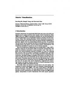
ENVIRONMENT
intention generator intention
habits
AGENT
behaviour control behaviour
filter
stimuli
sensors perception
motor control motor actuators physical model
motor action
Figure 9. A virtual fish agent’s internal structure (After Tu and Terzopoulos [49]) (cf. figure 1b). Reproduced with permission of MIT Press.
Pre-print: Dorin, A., Geard, N. (2014) "The Practice of Agent-Based Model Visualization", Artificial Life, Vol. 20, No. 2, 1–19.
Figure 10. One of Sims’ evolved virtual creatures and its controller (After Sims [45]). Reproduced with permission of MIT Press.
37
38
Figure 11. Vehicles, one that avoids the light and one that seeks it. (After Braitenberg [8, fig. 3].) Reproduced with permission of MIT Press.
Pre-print: Dorin, A., Geard, N. (2014) "The Practice of Agent-Based Model Visualization", Artificial Life, Vol. 20, No. 2, 1–19.
(a)
(b)
Figure 12. (a) Darwin’s sketch, First notebook on Transmutation of Species9 (1837) (b) Haeckel’s Pedigree of Man [26, p188, plate XV].
9
Image source http://en.wikipedia.org/wiki/File:Darwin_tree.png (accessed 12 Oct. 2011). 39