opers will be able to customize a complete document image understanding system ... transform paper documents into a hierarchical representation of their ...
THE PROTOTYPE OF A COMPLETE DOCUMENT IMAGE UNDERSTANDING SYSTEM J. LIANG, J. HA, R. ROGERS, I.T. PHILLIPSy, R.M. HARALICK, B. CHANDA Intelligent System Laboratory Department of Electrical Engineering, Box 352500 University of Washington Seattle, WA 98112
y
Department of Computer Science/Software Engineering, Seattle University Seattle, WA 98122
The goal of document analysis is to convert existing paper documents into a machine readable form which can be manipulated through word processors or information retrieval systems. In the Intelligent Systems Laboratory at the University of Washington, we have designed and partially implemented a complete document image understanding system which integrates various components. Document Attribute Format Speci cation (DAFS) is used as the interchange format for the document structure representation. Using our system, the researchers and developers will be able to customize a complete document image understanding system for a particular set of documents. Also, the user of our system can add new algorithms to any system module and able to do the performance evaluation for their newly modi ed systems. This paper presents the system architecture, the system development environment, and the prototype of the system.
1 Introduction The ultimate goal of a complete document image understanding system is to transform paper documents into a hierarchical representation of their structure and content. The transformed document representation enables document interchange, editing, browsing, indexing, ling and retrieval since the document content can be accessed by its logical structure rather than simply by its imaged form 1 . A complete document image understanding system may consist of a preprocessing module, a page layout analysis module, an OCR engine, a logical structure analysis module, and a le transformation module (see Figure 1). Each of these module may include several sub-modules. In general, given a document image or a set of document images, the page layout analysis module processes the given image(s) and produces the locations of the segmented homogeneous regions or blocks (such as text, math, gures, etc.) on these images. These segmented blocks are represented by a tree or a graph data structure called the \physical" structure. Each of these blocks 1
Paper Document Scan-digitization Document
Image
Layout Analysis Layout Structure Text Recognition
Logical Analysis
Content
Logical Structure Conversion Interchange Format Applications
Figure 1: illustrates the document understanding model.
is then classi ed as text or non-text. Those non-text blocks may be further classi ed. The text blocks are passed on to the OCR engine to produce ASCII text. The resulting physical structure and the ASCII text are passed on to the logical analysis module. The tasks for the logical structure analysis module may include assigning logical labels to text blocks (i.e., text body, section heading, etc.), and non-text blocks (photo, gures, etc.), determining reading order for those text blocks, grouping those non-text entities with their corresponding captions, and so on. The tasks may also include font classi cation and document style analysis. The result of the logical structure analysis module may be represented as a tree or a graph data structure called the \logical" structure of the input document. Finally, the le transformation module combines these two structures and the OCR results to produce a desired standard exchange le such as Rich Text Format (RTF) le or a Portable Document Format (PDF) le. In other words, this system transforms a physical document page into a computer-readable document le. These les may be viewed 2
from any platform and used for information retrieval. A few document image understanding system prototypes have been proposed and developed 2 ? 8 . All of these systems are variations of the model described above. However, problems exist among these systems. First, none of these systems are formally evaluated. Second, these systems are not portable, and their les and algorithms are not shareable. The extentability of these systems is also an issue. The performance of a document image understanding system using the model described above is dependent on the performance of the system modules: the page layout analysis, the OCR algorithm, and the logical structure analysis modules within the system. However, a simple integration of the best performing modules of their kinds may not make the best system of all. Another issue is the implementation platform and the shareability of the data and algorithms of the system. In the Intelligent Systems laboratory at the University of Washington, we have designed and partially implemented (prototyping) a generic document image understanding system that is portable and shareable to document research community. The design of our system is based on the model described above. However, within the system, images and data structures are represented in Document Attribute Format Speci cation (DAFS) format. The Illuminator is used as the graphical user interface. Both Illuminator and DAFS are public domain software and data structure. Therefore, our system is portable and shareable. The system is constructed under FormLib environment which allows users to setup di�erent sequences of routines. When our system is completely implemented, each module will include a set of well tested algorithms and a control unit that capable of selecting the \right" algorithm for the given data at each processing stage. This capability enables data training and customizing one's own system. Currently, the page layout analysis module of our prototype includes three in-house developed algorithms. These three algorithm have been tested and evaluated for their performances. Each of these three algorithms may outperform one another for a chosen set of documents. We also have integrated two in-house zone classi cation algorithms for the system. For the le conversion module, we have implemented two le conversion routines: DAFS to RTF and DAFS to PDF. Currently, the logical analysis module is in its design phase. We expect the implementation will take place shortly. Our system can be used by research and development community. Using our system, the researchers and developers will be able to customize a complete document image understanding system within days, not months, for a particular set of documents. Also, the user of our system can add new algorithms to 3
any system module and able to do the performance evaluation for their newly modi ed systems. The remaining of this paper is organized as follows. In Section 2, we describe the system environment and in Section 3, we give our system architecture. Section 4 includes the page layout analysis algorithms of our system, and the description of the two zone classi cation algorithms. A preliminary design of our logical analysis module is discussed in Section 5 and the le conversion module is given in section 6. Although we have not implemented the logical analysis module, we are able to demonstrate the functionality and the feasibility of the prototype of our system. The preliminary results are given in Section 7.
2 The System Environment The FormLib environment includes a library of document analysis routines and a control routine that follows the list of instructions speci ed in a con guration le. Data within FormLib is represented by the Document Attribute Format Speci cation (DAFS) le format. A graphical user interface called Illuminator enables the developers to read, write and work with DAFS les. Both DAFS and Illuminator are constructed, by RAF Technology, Inc., under the sponsorships of ARPA. The following sections give the description for the DAFS le format, FormLib environment, and Illuminator. 2.1 Document Attribute Format Speci cation (DAFS) The Document Attribute Format Speci cation (DAFS) 9 is a document interchange format for document decomposition and data sharing applications. The DAFS provides a format for breaking down documents into standardized entities, de ning entity boundaries and attributes, and labeling their contents (text values) and attribute values. Through DAFS, developers will be able to exchange training and test documents and work together on shared problems. DAFS permits the creation of parent, child and sibling relationships between entities, providing easy representation of the hierarchical structures of a document (see Figure 2). DAFS is designed explicitly for encoding decomposed documents (reverse encoding) and is designed to allow representation of both the physical and logical information contained within a document image. Entities within DAFS structure are regions within a given document such as the whole and part of a document image, text and gure blocks, text-lines or text-words. User may select to attach information for entities, such as the entity content (text,
4
subimage, etc.), property (bounding box, font and point size, etc.), physical type (text block, gure, etc.), logical type (author, section heading, etc.), and the relationships with other entities (such as the read orders). Document
Paragraph
Text Line
Word
Glyph
Paragraph
Text Line
Word
Glyph
Word
Glyph
Glyph
Figure 2: illustrates the DAFS hierarchical entity relationships. The nodes represent DAFS entities. The horizontal edges denote sibling relationships; while the vertical edges denote parent-child relationships.
2.2 FormLib
FormLib is designed as a software environment for document image analysis research and development. FormLib includes a driver and a library of document analysis routines such as image noise reduction routines, skew correction routines, page segmentation routines, OCR algorithms, logical analysis routines, and others. All routines within FormLib use DAFS entities for their inputs and outputs. The FormLib driver follows a set of instructions, de ned by the users, in the con guration le. Each instruction in a con guration le tells the driver which routine to call, which type of entity the called routine needs to operate on, and where the called routine needs to look for information regarding the given entities. Parameters which may be needed during the recognition are passed as properties of the entity or the entity type. The routine modi es the input DAFS entities and outputs the modi ed DAFS le. Within FormLib environment, users may add new routines to FormLib library then edit the con guration le to call the newly added routines. Since speci c document recognition architectures may be de ned within con guration les, FormLib provides a convenient experimentation environment for researchers and developers to determine the best algorithm for each processing step and the best processing sequence for a given set of documents. 5
2.3 The Illuminator Software Illuminator is a GUI (Graphical User Interface) for viewing and altering entities in DAFS les. Within Illuminator, one can edit documents that have a combination of text and images, and is capable of displaying both. It can handle text from any script or language supported by UNICODE for which the user has the appropriate display fonts. Japanese and most major European languages are currently available. It is a very e�cient editor for correcting machine-recognized documents. The resulting error-free documents can be used as training data for various kinds of document recognizers, as a reference set (groundtruth) for testing such recognizers, and for entry into databases. Illuminator is intended to be used by the OCR and document analysis research and development communities. Illuminator may also be used by those in the conversion business for providing accurate on-line data to the customer. Illuminator o�ers three modes of operation. Image Mode is for viewing and working with the actual image of a document and its entities. The entities are speci c regions of the image and are associated textual content. Out-ofContext Mode collects entities of the same type into a single le (e.g., all the A's from a page), where errors can easily be corrected. Flagged Mode provides easy means of correcting entities agged as questionable by OCR. (The Illuminator software can be obtained via anonymous ftp from documents.cfar.umd.edu in the /pub/contrib/sources/ directory, or from http://documents.cfar.umd.edu/ resources/source.)
3 The System Architecture The top level design of our system is shown in Figure 3. There are four main modules within our system: the physical layout analysis, the text recognition, the logical structure analysis, and the le conversion modules. The system consists of a control unit that capable of selecting the \right" algorithm for the given data at each processing stage. The design of this control unit is not included in this paper. Currently, we use a commercial OCR system within our text recognition module. The architectures of the other three modules are given next. 3.1 The Architecture for the Physical Layout Analysis Module The architecture of the physical layout analysis module is shown in Figure 4. Given a document image or a set of document images, the page layout analysis module calls the selected zone segmentation routine to partition the input image into a set of homogeneous regions or zones. Each of these zones is
6
System Overview Document Image
Layout Analysis Toolbox
Page Segmentation & Zone Classification
Layout Structure (DAFS)
Text Recognition Logical Analysis Toolbox
Logical Structure Extraction
Content
Control Strategy
User Logical Structure & Contents ( DAFS )
Style
Conversion
Conversion Routines
Interchange File
Figure 3: The document understanding system overview
then classi ed, by the zone classi er, as text or non-text. Those non-text zones are further classi ed as a math, table, gure, photo, ruling, etc. The text zones are passed on to text-line and text-word segmentation routines to produce bounding boxes for each text-line and text-word. The text-block extraction routine takes the text-line bounding boxes and produces the text-block bounding boxes. The segmented text-blocks are passed on to the system OCR engine to produce the text content. Note that, the input image, the ASCII text, the coordinates of the bounding boxes (zones, text-words, text-lines, and text-blocks), and the assigned zone types are represented in the DAFS le associated with the input image. As for the non-text zones, we have implemented a tabular structure analysis routine 22 , and this routine is included in the physical analysis module. 7
Document Image Zone Segmentation Zone Entities Zone Classification Text Zones
Non-Text Zones Drawing
Table
Tabular Structure Analysis
Text-Line Segmentation
Word Segmentation
Text-Lines
Row & Column Items
Words
Text-Block Extraction Text-Blocks
Figure 4: Physical Layout Analysis Module Diagram
3.2 The Architecture for the Logical Layout Analysis Module Our logical analysis module is still in its designing phase. The architecture of the logical structure analysis module is shown in Figure 5. This module includes the style analysis and logical analysis routines. Both routines are still in the design phase. Within this design, the style analysis routine takes the DAFS le (contains the results of the physical analysis module and the ASCII text from OCR) and determines the style of the input document. The observed style is given to the logical analysis module for assigning a logical label to each text entity within the DAFS le. Then, the logical analysis module determines the reading order for those text entities and groups those non-text entities with their corresponding captions. Finally, the text threads are constructed. The resulting DAFS le representing the physical and logical structure is then passed on to the le conversion module. 3.3 The Architecture for the File Conversion Module The goal of a complete document image understanding system is to transform paper documents into a desired standard exchange le such as an RTF, PDF, SGML, HTML, or LATEX le. These standard exchange les enable document interchange, editing, browsing, indexing, ling and retrieval.
8
Layout Structure Style Analysis Knowledge of Style
Observed Style
Logical Analysis Logical Structure
Figure 5: Logical Layout Analysis Module
We have implemented two le conversion routines. One converts DAFS les to RTF les and the other converts DAFS les to PDF les. The architecture of these two routines are shown in Figure 6. DAFS File Logical Structure
DAFS File
Content
Recognized Text & Font
Style
Layout Structure
Unrecognized Text Entity
Image
Microsoft Word
DAFS to RTF Converter
DAFS to PDF Converter
RTF File
PDF File
Editing & Reconstruction
Adobe Acrobat Products
(a)
Document Archiving
(b)
Figure 6: (a) DAFS to RTF le conversion routine; (b) DAFS to PDF le conversion routine.
4 Routines Within Physical Analysis Module Currently, the physical layout analysis module includes a skew correction routine, three in-house developed page segmentation algorithms and two in-house 9
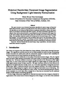
developed zone classi ers. A page segmentation algorithm using bounding boxes of connected components is described in Section 4.1. A bottom-up textline segmentation algorithm for severally degraded document images is given in Section 4.2. The zone classi cation routines are described in Section 4.3. The details of the document layout analysis method using recursive morphological transforms can be found in Chen's thesis 15 . 4.1 Page Decomposition Algorithm Using Bounding Boxes of Connected Components Once a paper document is at hand, it has to be scanned and thresholded, which results in a binarized document image. Usually, a document image consists of many connected components of black pixels. Document page decomposition can be accomplished by analyzing the spatial con guration of such connected components in a document image. Each connected component designates a complete or partial symbol. Symbols that are found in document pages may be classi ed into two groups: Single-component symbols and multiple-component symbols. Notice that all characters of English alphabet except `i' and `j' belong to the former group. Sometimes a single-component symbol can be `broken' into several pieces in a degraded image. In that case, the symbol is considered to be a multiple-component symbol. We choose to work with the bounding boxes of the connected components rather the pixels. The bounding box of a connected component (or a symbol) is de ned to be the smallest upright rectangle which circumscribes the connected component (or symbol). The bounding box projection approach has many advantages over the pixel projection approach. It is less computationally intensive. It is possible to infer from projection pro les how bounding boxes (and, therefore, primitive symbols) are aligned and/or where signi cant horizontal and vertical gaps are present. Now we brie y describe the page decomposition algorithm in a step-bystep manner. A detailed description of the algorithm may be found in 19 . The input of the algorithm is a binary document image. We assume that the input document image has been correctly deskewed.
Obtaining Bounding Boxes of Connected Components
A connected-component algorithm 17 is applied to the black pixels in the binary image to produce a set of connected components. Then, for each connected component, the associated bounding box is calculated. A bounding box can be represented by giving the coordinates of the top-left and the bottomright corners of the box. Each bounding box is considered as a smallest entity on the page. Note that, the number of bounding boxes are always more than 10
(a) 0
10
20
30
40
(b) 50
60
30 20 10 0
(c)
(d)
Figure 7: (a) an English document, (b) bounding boxes of connected components of black pixels, (c) horizontal projection pro le, (d) vertical projection pro le.
the number of symbols since multiple bounding boxes are produced for multicomponent symbols. Figure 7(a) shows a segment of an English document image (taken from the UW English Document Image Database I, page id \L006SYN.TIF") and Figure 7(b) shows the bounding boxes produced in this step.
Recursive X{Y Cut on Projections of Bounding Boxes
Analysis of the spatial con guration of bounding boxes can be done by projecting them onto a straight line. Since paper documents are usually written in the horizontal or vertical direction, projections of bounding boxes onto vertical and horizontal lines are of particular interest. For brevity, the projection of bounding boxes onto a vertical straight line is called horizontal projection. The 11
vertical projection is de ned analogously. By projecting bounding boxes onto a line, we mean counting the number of bounding boxes orthogonal to that line. Hence, a projection pro le is a frequency distribution of the bounding boxes on the projection line. Figures 7(c) and 7(d) shows the horizontal and vertical projection pro les of the bounding boxes in Figure 7(b). A document image may be segmented using the recursive X{Y cut 18 based on bounding boxes. At each step, the horizontal and vertical projection pro les are calculated. Then a zone division is performed at the most prominent valley in either projection pro le. The process is repeated recursively until no su�ciently wide valley is left. Each of the segmented zone is passed on to the zone classi er. The text zones are given to text-lines, text-words and text-blocks extraction routines.
Extraction of Text-lines
We determine the text-line direction of the page by analyzing both horizontal and vertical projection pro les. From Figure 7(c) and 7(d), it is clear that the text-lines are horizontally oriented; because there are distinct high peaks and deep valleys at somewhat regular intervals in the horizontal projection pro le, while no such features are seen in the vertical projection pro le. Since the bounding boxes are represented by a list of coordinates of the two corner points, the text-lines are easily extracted. The result is shown in Figure 7(f). Other important features, such as frequency distribution of text-line heights and inter-text-line spacings, can also be deduced from the horizontal projection pro le.
Extraction of Words
The vertical projection pro le for each text-line is computed. The algorithm considers each such pro le as a one-dimensional gray-scale image, and thresholds it at 1 to produce a binary image. During the binarization a symbol (or a broken symbol) with multiple bounding boxes may be merged into one. Consequently, adjacent symbols whose bounding boxes overlap each other are also merged. However, this will not cause any problem as we merge symbols' bounding boxes to form words. Figure 7(e) shows projection pro les within text-lines. The binarization is followed by morphological closing with a structuring element of appropriate length to close spaces between symbols, but not between words. The length is determined by analyzing the distribution of the run-lengths of 0's in the binarized pro le. In general, such a run-length distribution is bi-modal. One mode corresponds to the inter-character spacings 12
Figure 7:
(e)
(f)
(g)
(h)
(continued):
(e) vertical projection pro les, (f) text-line bounding boxes, (g) word bounding boxes, (h) text-block bounding boxes.
within words, and the other to the inter-word spacings. The bottom of the valley between these modes 21 20 gives the desired structuring element length. Figure 7(g) shows the results of this step. ;
Extraction of Text Blocks
The beginning of a text block, such as paragraph, math zone, section heading, etc., are usually marked either by changing the justi cation of the current text-line or by putting extra space between two text-lines: One from the previous paragraph and the other from the current one or by changing text height. So when a signi cant change in text-line heights, inter-text-line spacings, or justi cation occurs, we say that a new text block begins. The distributions of text-line heights and inter-text-line spacings together with the horizontal projection pro le give us cues for text block segmentation. Figure 7(h) shows 13
the text block bounding boxes for our example text. 4.2 A bottom-up line segmentation algorithm The heart of this line segmentation algorithm is a procedure which merges a set of connected component bounding boxes into line bounding boxes. Boxes are merged if and ony if the horizontal distance between them is small, and they overlap vertically. Unfortunately, noise and poor document layout result in poor performance with this simplistic algorithm. To cope with these problems, the set of connected component bounding boxes is ltered to eliminate noise and non-textual components before applying the line segmentation algorithm. Bounding box b is eliminated from B i�: � b.h > max_char_height � b.w > max_char_width � b.h / b.w > max_char_aspect � b.w / b.h > max_char_aspect
In severally degraded documents, characters in vertically adjacent text lines may be merged. This may cause the line segmentation algorithm to return bounding boxes which contain multiple text lines. To remedy this situation, the following algorithm is applied to the lines created by the line segmentation algorithm: for each line l if Count Merged Lines (l) > 1 then for each connected component cc in l n = Count Intersecting Lines (cc, l) split cc vertically into n equally tall connected components re-run line segmentation algorithm for connected components in l
The Count Merged Lines algorithm determines the number of vertically merged lines contained in a rectangular region l. It assumes that each line in the region contains at least one character which is not vertically merged. The algorithm provides correct results for regions contain text within a size range of up to twice a speci ed minimum height. The Count Intersecting Lines algorithm computes the number of text-lines in a rectangular region l which intersect a the speci ed connected component cc. The algorithm makes the same assumptions as the Count Merged Lines algorithm. 14
4.3 Zone Classi cation Algorithms Given a homogeneous zone entity, zone classi cation module classi es it according to its content. We have developed two methods using feature vector generation and classi cation to classify each given scienti c and technical document zone into one of the eight labels: text of font size 8-12, text of font size 13-18, text of font size 19-36, display math, table, halftone, line drawing, and ruling. The methods of feature selection are: � based on the distribution of the sizes of connected components 23 ,
moment features 24 . The decision tree classi er is trained and used to classify the given zones on the basis of feature vector. We have tested our method on UW-I document image data set with 979 pages and a total of 13726 zones. The performance of the algorithms for all zone types is above 95%. The accuracy for text and non-text distinction is greater than 97%. Two di�erent feature generation methods produce the similar result, but the rst method involves much less computation than the second one. Another method is to feed the zones to the OCR engine. For each block, a ratio � is computed as: �
of recognized symbols � = numbertotal area of block If � is larger than a certain threshold, the block content is classi ed as text. Otherwise, it is classi ed as non-text.
5 Design of the Logical Structure Analysis Modue The logical structure extraction refers to the problem of mapping the physical layout structure (See Figure 8(a)) into a speci c logical structure (See Figure 8(b)) consisting of meaningful objects. The logical structure analysis consists of the following sub-problems: � Text entity labeling (paragraph, title, section heading, caption, etc.) � Reading order determination � Threading detection (section, newspaper story, etc.) Group entities into larger logical units. 15
document page
header
document
live matter
illustrations
sections
footer
zones paragraphs
text blocks sentences/phrases
text lines words
words characters/symbols
(a)
characters/symbols
(b)
Figure 8: Tree representation of technical journal document (a) layout structure, and (b) logical structure.
Combine candidate paragraphs to reconstruct logical paragraphs broken during the typesetting process. The recognition of logical structure enables a variety of applications: document interchange, indexing, browsing, editing, retrieval, hyperlinking, etc., since the document content can be accessed by its logical structure rather than simply by its imaged form. Most of the logical structure analysis algorithms extract only partially the logical structure information for a speci c type of document. The objective of our research is to develop a logical structure extraction algorithm that can extract the complete logical structure from a broad range of documents. Our logical analysis algorithm will work completely independent of text recognition. Instead, it only utilizes style knowledge. These are: global knowledge about the logical entity location, the local knowledge about the formatting attributes of logical entity, and the spatial relations between logical entities. As a result, the logical structure of document image is analyzed by labeling entities by corresponding functional labels after hypothesizing and testing layout properties �
16
of the captured layout structure.
6 File Conversion Module After the extraction of document structure and content, and a speci cation of formatting attributes (style), the conversion module converts the document structure into a formatted document in a desired le format. This allows access to the original document contents in a form that is unconstrained by the original physical structure. The le format depends on the application, i.e., SGML for document interchange, RTF for editing, HTML for hyperlinking, and PDF for document archiving. 6.1 DAFS to RTF Conversion Routine The Rich Text Format (RTF) Speci cation 13 is a method of encoding formatted text and graphics for easy transfer between applications, including word processors. It provides a format for text and graphics interchange that can be used with di�erent output devices, operating environments, and operating systems. An RTF le consists of unformatted text and \groups", control words, control symbols and braces: using a de ned syntax, groups are used to format text and to identify such structure as annotations, color, fonts, footnotes, headers and footers, styles and le summary information. Given a DAFS le (contains the image, the logical structure, the physical structure, and the ASCII text), the DAFS to RTF routine performs the \reverse encoding" by mapping the entities in the DAFS le into an RTF le. The user can de ne the page style by editing the \style speci cation" le or the generated RTF le. A style speci cation le contains the description of the desired document style. The output page layout is decided by the style and logical structure. To produce an RTF le, an RTF header is needed. The user may de ne a special symbol look-up table to map special symbols from the original document to RTF. The style sheet group contains de nitions and descriptions of the various styles ( for example, the section heading style ) used in the document. The user can de ne the paragraph style by editing the style speci cation le. For each input entity type, the program will search the speci ed style conversion table. The paragraph's formatting properties follow the user's speci ed preferences. If no speci cation is found in the style le, the prede ned default style is used. The content is the same as the content of the DAFS entity. For a text entity, the content is the ASCII characters. For a non-text entity, the content is the bitmap of the entity area. An RTF le can include pictures cre-
17
ated with other applications. These pictures can be in hexadecimal or binary format. The bitmap and size information are extracted from the corresponding DAFS entity. 6.2 DAFS to PDF Conversion Routine Portable Document Format (PDF) 14 is a native le format of Adobe Acrobat family of products which enable users to easily and reliably exchange and view electronic document independent of the environment in which they are created. PDF les can be distributed across virtually any medium, from CD-ROM to the World Wide Web. PDF relies on the imaging model of the PostScript language to describe text and graphics in a device- and resolution-independent manner. Given a DAFS le (contains the image, the logical structure, the physical structure, and the ASCII text), the DAFS to PDF conversion routine converts the DAFS le into a PDF le. The original documents are turned into accurate, searchable electronic les which faithfully retain the rich look and the feel of printed documents. Note that the DAFS to PDF converter does not need the information of the logical structure. The option of generating PDF output is for the applications that users want the computer to capture the document just the way it looks on paper. The recognized content and font attribute of text entities (text-lines or words) are used to build the PDF objects which retain the exact location of these text entities. The non-text entities and unrecognizable text entities are output as PDF image objects. This feature of preserving the \suspect" characters will allow some users to completely skip the costly clean-up (error correction) steps normally associated with OCR processing. The PDF les are bigger than text les and smaller than scanned image les. TM
TM
TM
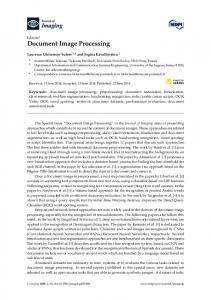
7 Preliminary Results To test our partially implemented system, we have randomly selected dozens of document images from UW-III document image database 25 and apply our prototype to these images. The results demonstrate the functionality and the feasibility of the prototype of our system. The following gives the operation steps and the results of our prototype on the image C04F (C04F is the page ID used in UW-III). Note that, the shown results are for the demonstration purpose. A systematic performance evaluation of our system is yet to be done. The prototype processing sequences for C04F image is as follows. The connected component based recursive X{Y cut segmentation routine is applied 18
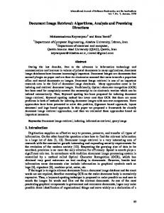
to the image of C04F. Figure 7 illustrates the result of this operation. The segmented zones on the image are passed on to the zone classi er. Those text zones are passed on to the text-line extraction routine, and the extracted textlines are passed on to the text-word extraction routine. Figures 10 and 11 show the results of segmented text-lines and text-words. Each of the extracted words is passed on to the system OCR engine to produce ASCII text. Note that, at this point, the physical structure of C04F has been constructed in a DAFS structure. The DAFS to RTF routine is called to convert this DAFS le to an RTF le. Text within the RTF le are the ASCII text of those text block entities within the DAFS le. Non-text DAFS entities are encoded as bitmaps within RTF le. Currently, the DAFS to RTF routine constructs the text reading order by following the physical order (top-down and left-right) of the text blocks on the page. The routine also estimates the point size of each text block using the mean height of the text-lines within the text-block. The other variables, such as number of columns, font, and justi cation, are speci ed by the user. We use Microsoft Word to reconstruct the document from the generated RTF le. The output one-column page (see Figure 12) is compared with the original page to validate our methods. TM
8 Summary and Future Work In this paper, we presented a document analysis system which is being developed at the University of Washington's Intelligent Systems Laboratory. We integrate the major components of a complete system, such as page segmentation, text recognition and automatic markup, in the FormLib environment. For future work, we want to optimize the existing algorithms and add new functionality. In order to build a robust and e�cient system, we are focusing on the performance evaluation of each module and trying to nd the appropriate modules for documents with di�erent kinds of layout and content. The system will be tested on signi cant sized data sets.
Acknowledgments The authors wish to thank the Washington Technology Center and RAF Technology, Inc. for their kind support of this work. 19
1
3
4
5
2
7
8
9
6
10
Figure 9: Page segmentation: Block extraction result.
References 1. G. B. Porter III and E. V. Rainero, Document Reconstruction: A System for Recovering Document Structure from Layout, Proceedings of Electronic Publishing, 1992, pp. 127-141, Lausanne, Switzerland, 1992. 2. H. S. Baird, Anatomy of a Versatile Page Reader, Proceedings of The IEEE, Vol. 80, No. 7, pp. 1059-1065, July 1992. 3. A. Dengel, R. Bleisinger, R. Hoch, F. Fein, and F. Hones, From Paper to O�ce Document Standard Representation, IEEE Computer, Vol. 25, No. 7, pp. 63-67, July 1992. 4. G. Nagy, S. Seth, and M. Viswanathan, A Prototype Document Image Analysis System for Technical Journals, IEEE Computer, Vol. 25, No. 7, pp. 10-21, July 1992. 20
C04F.dr
Figure 10: Page segmentation: Text line extraction result.
5. S. Tsujimoto and H. Asada, Major Components of a Complete Text Reading System, Proceedings of The IEEE, Vol. 80, No. 7, pp. 1133-1149, July 1992. 6. T.A. Bayer, Understanding Structured Text Documents by a Model Based Document Analysis System, 2nd ICDAR, pp. 448-453, Tsukuba, 1993. 7. S.L. Taylor, M. Lipshutz, D.A. Dahl and C. Weir, An Intelligent Document Understanding System, 2nd ICDAR, pp. 107-110, Tsukuba, 1993. 8. G. K. Myers and P.G. Mulgaonkar, Automatic Extraction of Information from Printed Documents, Fourth SDAIR, pp. 81-88, Las Vegas, 1995. 9. RAF Technology, Inc., DAFS: Document Attribute Format Speci cation, 1995. 10. RAF Technology, Inc., DAFS Library: Programmer's Guide and Reference, 1995. 11. RAF Technology, Inc., Illuminator User's Manual, 1995. 21
C04F.dr
Figure 11: Page segmentation: Word extraction result.
12. 13. 14. 15. 16. 17. 18. 19.
RAF Technology, Inc., Programmer's Guide to the Form Library, 1995. Microsoft, Rich Text Format (RTF) Speci cation, 1994. Adobe Systems Inc., Portable Document Format Reference Manual, 1993. Su Chen, Document Layout Analysis Using Recursive Morphological Transforms, Ph.D. thesis, Univ. of Washington, 1995. R.M. Haralick, Document Image Understanding: Geometric and Logical Layout, Proceedings 1994 IEEE Computer Society Conference on Computer Vision and Pattern Recognition, pp. 385-90, 21-23 June 1994. R.M. Haralick and L.G. Shapiro, Computer and Robot Vision, Volume I, Addison-Wesley, 1992. G. Nagy and S. Seth, Hierarchical Representation of Optically Scanned Documents, Proc. 7th ICPR, pp. 347-349, Montreal, 1984. J. Ha, I. T. Phillips and R. M. Haralick, Document page decomposition using bounding boxes of connected components of black pixels, Proc. 22
SURFACE REFLECTlVlTY MEASUREMENTS Fly. l7. Neutron reflec:lvlty as a functlon of Q (, 4x sin 8/A) for a l5OO-amystro::z thlcll dlblocl( copoly"ler (pol"tvrene4polr zrze!hylme!Nacrylaie) mmMlayer deposlled on a slllcon swDslm!e. The eolld ll"e repreeent8 celcula:ed reflec(iwl:v fol, :ll" da!a 8llo4n. T"e calculatlon 4as pedo"wad w To"l Ru8sell, lBM Almaden Research Lebs.
wavelength measured in angstroms-it is well under a degree for thennal neutrons. As the angle of incidence increases above the cntical angle, less and less of the incident neutrons are reflected by the surface. ln fact, rellectivity, which zeasures the fraction of neun-ons reilected from the surface, obeys the sa:ne law, discovered by Fresnel, that applies to the reflection of hght: reflectivity decreases as the fourth power ofthe angle ofincidence at suMciently large grazing angles. However, Fresnel's law applies to reflection of radiahon froz the smooth, flat surface of a honiogeneous nmtchal. lf the material is inhonmgeneous and there is a vahation ofthe scattennglength density perpendicular to the surface, the neutron reflechvity, zeasured as a function ofthe angle ofincidence, shows a niore complicated behavior. By keeping the retlection angle, O, snull, neutron reflectozetry can be used to probe density vahations in the surface to depths of a few thousand angstronu with a resoluhon of a few angstronis. Most of today's technical gadgets are either painted or coated in sonie fashion to prevent corrosion or wear. Reflectometry can often provide useful infonnation about such protective laycrs. Figure l7, for exarnple, shows the rellectivity, nmasured on the LANSCE Surface Proh!e Analysis Rellectozeter (SPEAR), froz a l5OO-angstroz layer of diblock copolymer (polystyrenepolynmthylmethacrylate) multilayer deposited on a silicon substrate. The spacing ofthe undulations in this result provides a direct nieasure of the average thickness of the polynier layers in the hlz. \4Men the detailed shape of the rcflectivity prohle is conipared with theoretical predictions, the density and thickness of the polynmr layers, as well as the thickness ofthe interface between layers, can be deduced. Neutron reflectonietry is a relatively new technique. lt is also one ideally suited to spallation sources. ln the next few years l expect the zethod to provide new infonnation on subjects as diverse as the recycling of polymers, nugnetic recording zedia, and the cleanup of oil spills. For sozeone like ze who has been associated with neutron scattenng for nmre than twenty years, tlm birth of this new technique is a happy event. lt nmans that there are still qualitative!y new ways in which neun,ons can help unravel the comp!ex structures of the nmtenals on which we depend. z
Figure 12: The page generated from RTF le by Microsoft WordTM .
SPIE 95, Document Recognition II, Vol. 2422, pp. 140-151, 1995. 20. J. Kittler and J. Illingworth, Minimum Error Thresholding, Pattern Recognition, Vol. 9, pp. 41{47, 1986. 21. Nobuyuki Otsu, A Threshold Selection Method from Gray-level Histograms, IEEE Trans. on Systems, Man, and Cybernetics, Vol. SMC-9, pp. 62{66, 1979. 22. J. Liang, J. Ha, R.M. Haralick, I.T. Phillips. Document Layout Structure Extraction Using Bounding Boxes of Di�erent Entities. Accepted by IEEE Workshop on Applications of Computer Vision 1996. 23. J. Liang, I.T. Phillips, J. Ha, R.M. Haralick. Document Zone Classi cation Using the Sizes of Connected Components. Proceedings of the SPIE, Vol 2660, Document Recognition III, pp 150{157, San Jose, 1996. 23
24. R. Sivaramakrishnan, I.T. Phillips, J. Ha, S. Subramanium, and R.M. Haralick. Zone Classi cation in a Document using the Method of Feature Vector Generation. Proceedings of the Third ICDAR, Vol. 2, pp. 541544, Montreal, 1995. 25. I.T. Phillips. User's Reference Manual for the UW English/Technical Document Image Database III. UW-III English/Technical Document Image Database Manual, 1996. 26. K. Summers, Toward a Taxonomy of Logical Document Structures, Electronic Publishing and the Information Superhighway: Proceedings of the Dartmouth Institute for Advanced Graduate Studies (DAGS '95), pp. 124-133, Boston, 1995.
24