The Real-Time Simulator for Protective Relays Testing Using MATLAB/Simulink Software Adam Smolarczyk
Ryszard Kowalik
Emil Bartosiewicz
Warsaw University of Technology Warsaw, Poland
[email protected]
Warsaw University of Technology Warsaw, Poland
[email protected]
Warsaw University of Technology Warsaw, Poland
[email protected]
Abstract—The submitted paper presents a tester designed for testing the protective relays in work conditions close to the real. The device is a simulator operating in real-time of the phenomena taking place in the modeled part of power system. The paper describes the construction (including hardware and software aspects) and operation principle of designed simulator. The MATLAB/Simulink software has been used for modeling the test systems (as parts of the whole power system). Paper includes some example results of distance relay tests performed using designed simulator. In addition, the opportunities for further development of both hardware and software parts of the simulator have also been presented.
that the tests should be performed according to specific test procedures.
Keywords—power system protections; protective relays testing; real-time simulators; closed-loop testing, MATLAB/Simulink software
Different applicable divisions of protective relays tests have been described in [1]. There are two main types of relay testing: type tests and individual tests [1-3]. Among the type tests, significant are: functional conformance tests, functional performance tests and scheme performance tests. The listed types of tests are carried out using suitable devices known as: (a) the microprocessor testers, (b) simulators reproducing the recorded waveforms or waveforms generated using simulation software (simulators operating in open loop), (c) simulators operating in real-time of phenomena (simulators operating in closed loop). Devices applicable by users for performing the tests of protective relays are more thoroughly described in [4].
ACRONYMS PS
Power System.
DFR
Digital Fault Recorder.
RTS
Real Time Simulator.
RTDS
Real Time Digital Simulator.
IEn-RTS
Institute of Electrical Power Engineering -Real Time Simulator.
RTWT
Real-Time Windows Target.
DC
Direct Current.
DAC
Digital-Analog Converter.
COMTRADE
Common Format for Transient Data Exchange for Power Systems.
I. INTRODUCTION A quick introduction of the new advanced digital protection relays, and the multitude of features included therein, may result in their operating not in the full accordance with users expectations. For this reason, relays should be tested by the manufacturers both in the production phase as well as during operation. A variety of issues to check means
th
18 Power Systems Computation Conference
The aim of the relays testing is to confirm correctness of their operation in accordance with manufacturer's design and with user's requirements. Evaluation of their operation during the tests contributes to determine their suitability for intended application, and hence for appropriate protection of particular elements of the power system (PS) and protection of this PS as a whole. Performing the tests allows manufacturers to draw conclusions about the operation of the relays and about improvement of old and creation of new solutions.
The remainder of this paper is organized as follows. Section II presents a brief description of each types of tests and tools for their implementation, with the main emphasis on clarifying the principle of testing in closed loop (using simulators operating in real-time of phenomena). Section III describes the self-designed simulator for testing protective relays in a closed feedback loop. Section IV presents selected results of tests performed using the simulator. Section V concerns the prospects of further simulator development. Summary is stated in Section VI. II. METHODS FOR TESTING THE PROTECTIVE RELAYS The following briefly describes some of the methods for testing the protective relays.
Wroclaw, Poland – August 18-22, 2014
A. Functional conformance tests Within this type of tests, the relay is checked using the signals that can be expressed by simple dependencies between currents and voltages. During the tests, protective relay is supplied with the analog signals, usually defined as fundamental-frequency phasors. Sometimes an additional aperiodic component is added to pure-sine wave test signals. During the tests are simulated the pre-fault, fault and postfault conditions. Functional conformance tests are performed using common microprocessor testers cooperating with highend amplifiers [4, 5].
currents (obtained from the simulator) are converted to analog signals, properly amplified and then put into the relay. The other hand, binary output signals from the relay are put into the PS model mapped in simulator. If the output signal is a tripping signal and this signal occurs during the simulated phenomenon, then the corresponding circuit in a system model is interrupted. Such a test is said to be carried out with a closed loop, as the behavior of the modeled system is affected by operation of the tested relays (as in a real PS). Described above method of the signal flow is visually presented in Fig. 1 and the construction and operation principle of PS real-time simulators are described in [4, 5].
B. Functional performance tests These tests concern the operation correctness of the relay in particular PS work conditions and the specific course of fault in PS. They can be performed in such a way that the waveforms of electrical quantities (just before and during the disturbance) are recorded using digital fault recorder (DFR). Then the recorded waveform is transferred via storage medium to the laboratory and uploaded to the tester software (simulator reproducing the recorded waveforms). If the recorded waveforms are not available, then the waveforms of electrical quantities may be obtained using a computer simulation of the PS or its suitable part.
Commercial simulators such as Real Time Digital Simulator - RTDS [6] or HYPERSIM Power System RealTime Simulator [7] are very expensive devices. Therefore, some academics are trying to build (with greater or lesser success) their own simulators working in real-time of phenomena [8] which could be used for testing the protective relays.
Tester reproduces the recorded waveforms of currents and voltages (modern microprocessor testers typically have the ability to reproduce the recorded waveforms), converts digital signals to analog and amplifies them to the level of tested relay's inputs. These signals are put into the tested device and its operation is observed with the pick-up and trip signals recording. These type of tests are called the open-loop tests. C. Scheme performance tests This testing method consists in that the protective relay is treated as a "black-box" wherein all the features are configured and set as in the case of its switch-bay application. The method of relay testing may be similar as in the case of functional performance tests. However, a much more sophisticated and conforming to the reality is a method of testing using the real-time simulators of PS event. Thanks to such the simulators, simulation results are lead out as fast as the system's phenomenon runs. With this type of simulator, tested relay can be incorporated into the PS model in such a way that the instantaneous values of voltages and
III. THE SIMULATOR FOR TESTING PROTECTIVE RELAYS IN REAL-TIME The laboratory has created the IEn-RTS simulator for testing protective relays in real-time of phenomena. The concept of a simulator working under the laboratory stand is described in [9]. The task of the simulator is the simulation of different phenomena (short circuits, power swings, voltage spikes, switching on the network, etc.) in the modeled parts of PS using the software able to simulate the dynamic states in PS. Obtained from the selected measurement point, appropriate voltage and current waveforms and the signals of breaker poles positions, which are the results of the simulation, appear at the outputs of measurement cards after the proper scaling. After signals amplification to the values corresponding to secondary sides of current and voltage transformers (using the current-voltage amplifier) and matching binary signals (using circuit which matches this signals to 220 V DC voltage), analog and binary signals are put into the device under test. In return, from the tested relay are taken the binary signals (e.g. signals indicating opening or closing the poles of appropriate circuit-breaker) which (through the matching circuits and acquisition card) affect to the status of switch devices in modeled (using simulation software) part of PS. The changes,
Real-time simulator Analog and binary outputs module Interface for information exchange with PC
Analog signals
Binary inputs module Binary signals
Analog and binary outputs module Binary outputs module
Output amplifiers Analog and binary inputs module
Interface for information exchange with PC
Device under test
Fig. 1. Signals flow process during the protective relays testing using a simulator operating in real-time of phenomena.
th
18 Power Systems Computation Conference
Wroclaw, Poland – August 18-22, 2014
being a result of tested relay operation in modeled part of PS, occur in the real-time of modeled phenomena (i.e., time in which they occur in reality).
In laboratory stand have been used Advantech measurement cards: two PCI-1720 cards (Fig. 3a) [11] and one PCI-1750 card (Fig. 3b) [12]. All measurement cards have been mounted in PCI busses of the PC. Each PCI-1720 card is equipped with four isolated analog channels (2.5 kV DC isolation) with controlled output voltage in the range of 0 to +/-5 V for voltage peak value. Resolution of each channel of digital-analog converter (DAC) is 12 bits. Voltage within the above-mentioned range (one of the card ranges foreseen by the manufacturer) is required by the input circuits of amplifier which has been used. In the laboratory stand, one card is used to amplify (using external amplifier) 3 current signals (L1, L2, L3 phases) and the other card to amplify 3 voltage signals (L1, L2, L3 phases).
Currently, using the created simulator may be tested protective relays which use analog signals (3 current signals and 3 voltage signals) and binary signals from the one of line's ends. This limitation is due to the number of installed measurement cards and capabilities of used amplifier allowing to generate up to 3 current signals and 3 voltage signals. Built IEn-RTS simulator consists of hardware and software parts. Fig. 2a shows a view of hardware implementation of the simulator, while Fig. 2b illustrates its block diagram.
a)
PC computer with the acquisition cards
CMS156 amplifier
Protective relay Analog signals (In=1A, Vn=100V)
Analog signals (+/-5Vpk AC)
Imax = 3 x 25A, Vmax = 3 x 250V
220 V DC matching circuit
Digital signals (0 - 5V DC)
b)
CMS156 amplifier
b) PC computer with the acquisition cards Card no. 1: PCI-1720
3xI
Analog outputs (currents)
Digital signals (220V DC)
Currents (0- 5Vrms)
3xV
Protective relay
Voltages
Analog inputs
Analog outputs
(0- 5Vrms)
Card no. 2: PCI-1720
Currents (3 x 25A max)
3xI 3xV
Voltages (3 x 250V max)
Currents (In=1 A)
Analog inputs
Voltages (Vn=100 V)
Binary inputs (220V DC)
Binary outputs (220V DC)
Analog outputs (voltages)
PC computer - Windows XP with SP3 - Matlab/ Simulink: - SimPowerSystems - Real-Time Windows Target
220 V DC matching circuit
Card no. 3: PCI-1750
8 signals
Digital outputs Digital inputs
8 signals
Digital inputs (0 - 5V DC) Digital outputs (0 - 5V DC)
Binary outputs (220V DC) Binary inputs (220V DC)
8 signals (max)
8 signals (max)
Fig. 2. A view of: a) the physical realization of the IEn-RTS simulator, b) block diagram for IEn-RTS simulator.
A. Simulator's hardware The hardware part of IEn-RTS simulator consists of: a) a PC; (b) acquisition PCI cards; (c) amplifier of current and voltage signals; (d) 220 V DC matching circuit; (e) the protective relay. PC computer has been equipped with an Intel Pentium 4 2.4 GHz processor, a P4P800SE motherboard from ASUSTeK company, 1.5 GB of RAM memory and a 500 GB hard drive. PC worked under Windows XP with Service Pack 3.
th
18 Power Systems Computation Conference
a)
b)
Fig. 3. Appearance of used acquisition cards: a) PCI-1720, b) PCI-1750.
Wroclaw, Poland – August 18-22, 2014
PCI-1750 card is equipped with 16 isolated digital inputs and 16 isolated digital outputs (2.5 kV DC isolation). For digital inputs, voltage should be in the range of 0 – 2 V (low state) and in the range of 5 – 50 V (high state). For digital outputs, voltage should be in the range of 5 - 40 V. In the simulator, PCI-1750 is used (along with a circuit matching to 220 V DC voltage) for putting signals to the binary inputs of protective relay (information on the switch poles positions) and to read information from the binary outputs of the relay (indicating its tripping) and affecting the switches status (open/close signal) in modeled part of PS. The use of 8 digital inputs and 8 digital outputs of PCI-1750 card has been provided for in the simulator. For amplification of the analog signals (currents and voltages) which have been generated by PCI-1720 card, a CMS 156 amplifier (from OMICRON electronics) has been used (Fig. 4a) [14]. It is equipped with 3 current channels and 3 voltage channels. The input voltage for the current and voltage channels should be in the range of 0 to 5 V for RMS values. Gain for particular current channels is 5 A/V, while for the voltage channels is 50 V/V. The range of output currents (RMS value) is from 0 to 25 A for each channel for three-phase amplifier operating-mode. The range of output voltages is from 0 to 250 V (RMS value) for each channel (for three-phase amplifier operating-mode too). The values of these signals conform to the analog signals at the secondary side of transformers and they are sufficient for testing most of protection relays with input rated current In = 1 A and with rated phase-to-phase input voltage Vn = 100 V. a)
b)
Fig. 4. Appearance of: a) CMS 156 amplifier, b) front panel of the 220 V DC matching circuit.
Connections between PCI-1720 measurement cards and CMS 156 amplifier have been made, in addition to standard connectors, using the16-pin Lemo FGG.2B [15] to which the amplifier's analog inputs system is adapted. To adjust the digital input and output voltages of the PCI-1750 card to values acceptable by binary inputs and outputs of tested protection relay, it has been made the circuit matching the card's voltages to 220 V DC level (Fig. 4b). This circuit can work with up to 8 digital inputs and 8 digital outputs of acquisition card, and hence with 8 binary inputs and 8 binary outputs of tested relay. Due to the fact that many relays often uses only 3 binary inputs and 3 binary outputs (breaker poles for L1, L2 and L3 phases) a large number of available binary inputs/outputs of matching circuits will be used after simulator development, for example to testing the operation coordination of the distance relays or the section relays (differential relays and phase comparison relays). As is known, relays of this type could work together (by transferring digital signals to each other) using a
th
18 Power Systems Computation Conference
telecommunication link, a direct fiber or using a IEC 61850 standard. B. Simulator's software The software part of the simulator includes MATLAB/Simulink software (ver. 2010b) along with RealTime Windows Target (RTWT) and SimPowerSystems toolboxes [16]. Order to run correct interaction of PCI-1720 card and PCI-1750 card with RTWT library items, it was also necessary to install the C++ compiler available in the Microsoft Visual Studio 2005 programming environment. The MATLAB/Simulink software along with the listed libraries is used to simulate (in modeled part of PS) dynamic phenomena such as faults (metallic faults, resistive faults, developing faults), power swings, switching on the network, etc. Moreover, analog and digital signals are forced from the software using the acquisition cards. They are taken from selected measurement points of modeled system, as the results of performed simulation. In addition, software is used to read the information (digital signals) resulting from the operation of tested relay (e.g., tripping signals for opening the poles of selected breaker) which affect the configuration of the modeled PS part. Simulation of selected PS part is performed with use of PS components available in SimPowerSystems library. In this library could be found the models of elements such as: synchronous and asynchronous machines, direct-current machines, regulators, current and voltage sources, transmission lines, one- and three-phase switches, transformers, passive elements, power electronic devices (diodes, thyristors, transistors, etc.). This allows to build a variety of electric power systems. The RTWT library contains elements such like (among the others) analog inputs and outputs or digital inputs and outputs, designed to work with acquisition cards. These elements are used in the simulator to lead out analog and digital signals (which are the simulation results) to acquisition card outputs (for their further processing through analog-signal amplifier and matching-circuit for digital signals) and to read the states of external digital signals affecting the course of the simulation. The choice of RTWT library has made possible the real-time simulation of phenomena in modeled PS parts. Analog and digital waveforms turn up at the inputs of tested relay in real-time (as in a real system), and the tested relay affects the modeled system configuration (and consequently the further course of the simulation) in a real-time using its binary outputs. IV. SELECTED RESULTS OF SIMULATOR OPERATION CORRECTNESS TEST The following describes the example test results for selected distance protection performed using created simulator. Currently, the following test systems are prepared in MATLAB/Simulink software:
Wroclaw, Poland – August 18-22, 2014
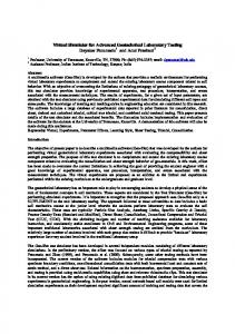
• 1st system - system with a voltage source operating onload; • 2nd system - system with two voltage sources (in this one controlled voltage source) connected by two transmission lines; • 3rd system - system with a generator (2nd order model, equation of motion only) and a voltage source which are connected by two transmission lines; • 4th system - system with a generator (5th order model) and a voltage source which are connected by two transmission lines. The assay systems for testing the protection relays were made with use of the components available in the SimPowerSystems library. Schemes for the 2nd, 3rd and 4th test systems are shown in Fig. 5. These systems differ from each in the PS1 source type connected to the BB1 busbar. PS1
BB1 BR3 F1
BR5
BR1
L2 F2
L1
BR4
BR2
BB2 PS2
BR6
Z