Feb 23, 2018 - Iulia Dragomir1, Viorel Preoteasa2, and Stavros Tripakis2,3. 1 Univ. ... definition "ReceptiveSqrt = [: x ; y . x ≥ 0 −→ y = √ ... sion of SqrRoot: it returns an arbitrary (but non-negative) y, and not necessarily the square-root of x. ... the operator 2, when applied to the predicate on infinite traces (x > 0) : (nat →.
The Refinement Calculus of Reactive Systems Toolset? rtifact * onsi st
se eu
*
at e d
arXiv:1710.08195v3 [cs.LO] 23 Feb 2018
* Easy to ed R nt
alu
Univ. Grenoble Alpes, CNRS, Grenoble INP?? , VERIMAG, France 2 Aalto University, Finland 3 University of California, Berkeley, USA
Abstract. We present the Refinement Calculus of Reactive Systems Toolset, an environment for compositional modeling and reasoning about reactive systems, built on top of Isabelle, Simulink, and Python.
1
Introduction
The Refinement Calculus of Reactive Systems (RCRS) is a compositional framework for modeling and reasoning about reactive systems. RCRS has been inspired by component-based frameworks such as interface automata [3] and has its origins in the theory of relational interfaces [14]. The theory of RCRS has been introduced in [13] and is thoroughly described in [11].
Options (translation strategy, etc.) Fuel Control System Model
RCRS theory and component library (Isabelle theory files)
This model uses only the ODEs to implement the dynamics.
theta [0 90] 1 throttle input (deg) [0, 81.2]
1 .1s+1
1 A/F
Throttle del ay1 1 s
f(u)
8.8
ODE1
Base opening angle
~=
1 s
1 s
f(u)
pe
double
2
~=
Fuel Cmd Open Pwr
Analyzer
f(u)
0.0
f(u)
airbyfuel_ref
14.7
lambda
f(u) ODE3
incompatiblity detection
12.5
p
f(u) ODE2
ODE4 Open
ODE4 Closed
~=
Fuel Cmd Open
1 s
~=
i f(u) f(u)
Fuel Cmd Closed
InputPoly
2 engine speed (rpm) [900,1100]
pi/30
AND
(rpm) to (rad/s)
internal variable elimination
Power Mode Guard boolean Starup Mode
In
Out
Startup Mode Latch
boolean FaultInjection
In
Out
Sensor Failure Detection Latch
1: Failure 0: Normal
OR
3 controller_mode NOT
Powertrain Control Benchmark Model Toyota Technial Center 2014 This is a model of a hybrid automaton with polynomial dynamics, and an implementation of the 3rd model that appears in "Powertrain Control Verification Benchmark", 2014 Hybrid Systems: Computation and Control,
Translator
X. Jin, J. V. Deshmukh, J.Kapinski, K. Ueda, and K. Butts
Simulink diagram
RCRS model of the diagram
(built on top of Isabelle theorem prover)
auto generated top-level contract refinement checking ...
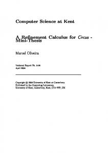
Fig. 1: The RCRS toolset.
RCRS comes with a publicly available toolset, the RCRS toolset (Fig. 1), which consists of: – A full implementation of RCRS in the Isabelle proof assistant [9]. – A set of analysis procedures for RCRS components, implemented on top of Isabelle and collectively called the Analyzer. ?
??
This work has been supported by the Academy of Finland and the U.S. National Science Foundation (awards #1329759 and #1139138). The first author was partially supported by the H2020 Programme SRC ESROCOS and ERGO projects. Institute of Engineering Univ. Grenoble Alpes
Ev
1
l We
Iulia Dragomir1 , Viorel Preoteasa2 , and Stavros Tripakis2,3
*
cu m e
A TAC C S *
* Complete
*
t en
* AECl Do
A
– A Translator of Simulink diagrams into RCRS code. – A library of basic RCRS components, including a set of basic Simulink blocks modeled in RCRS. An extended version of this paper contains an additional six-page appendix describing a demo of the RCRS toolset [6]. The extended paper can also be found in a figshare repository [7]. The figshare repository contains all data (code and models) required to reproduce all results of this paper as well as of [6]: see Section 7 for more details. The RCRS toolset can be downloaded also from the RCRS web page: http://rcrs.cs.aalto.fi/.
2
Modeling Systems in RCRS
RCRS provides a language of components to model systems in a modular fashion. Components can be either atomic or composite. Here are some examples of atomic RCRS components: definition definition definition definition definition definition definition definition
"Id = [: x ; y . y = x :]" "Add = [: (x, y) ; z . z = x + y :]" "Constant c = [: x::unit ; y . y = c :]" "UnitDelay = [: (x,s) ; (y,s’) . y = s ∧ s’ = x :]" √ "SqrRoot = {. x . x ≥ 0 .} o [- x ; x -]" "NonDetSqrt = {. x . x ≥ 0 .} o [: x ; y . y ≥ 0 :]" √ "ReceptiveSqrt = [: x ; y . x ≥ 0 −→ y = x :]" "A = {. x . 23x .} o [: x ; y . 23y :]"
Id models the identity function: it takes input x and returns y such that y = x. Add returns the sum of its two inputs. Constant is parameterized by c, takes no input (equivalent to saying that its input variable is of type unit), and returns an output which is always equal to c. UnitDelay is a stateful component: s is the current-state variable and s’ is the next-state variable. SqrRoot is a non-input-receptive component: its input x is required to satisfy x≥0. (SqrRoot may be considered non-atomic as it is defined as the serial composition of two predicate transformers – see Section 3.) NonDetSqrt is a non-deterministic version of SqrRoot: it returns an arbitrary (but non-negative) y, and not necessarily the square-root of x. ReceptiveSqrt is an input-receptive version of SqrRoot: it accepts negative inputs, but may return an arbitrary output for such inputs. RCRS also allows to describe components using the temporal logic QLTL, an extension of LTL with quantifiers [11]. An example is component A above. A accepts an infinite input sequence of x’s, provided x is infinitely often true, and returns a (non-deterministic) output sequence which satisfies the same property. Composite components are formed by composing other (atomic or composite) components using three primitive composition operators, as illustrated in Fig. 2: C o C 0 (in series) connects outputs of C to inputs of C 0 ; C ** C 0 (in parallel) “stacks” C and C 0 “on top of each other”; and feedback(C) connects the first output of C to its first input. These operators are sufficient to express any block diagram, as described in Section 4.
x x
y C
y C
0
(a) serial: C o C 0
z
u
y
x1
C C0
v
(b) parallel: C ** C 0
x2 .. .
y1 C
y2 .. .
(c) feedback: feedback(C)
Fig. 2: The three composition operators of RCRS.
3
The Implementation of RCRS in Isabelle
RCRS is fully implemented in the Isabelle theorem prover. The RCRS implementation currently consists of 22 Isabelle theories (.thy files), totalling 27588 lines of Isabelle code. Some of the main theories are described next. Theory Refinement.thy (1209 lines) contains a standard implementation of refinement calculus [1]. Systems are modeled as monotonic predicate transformers [4] with a weakest precondition interpretation. Within this theory we implemented non-deterministic and deterministic update statements, assert statements, parallel composition, refinement and other operations, and proved necessary properties of these. Theory RefinementReactive.thy (1144 lines) extends Reactive.thy to reactive systems by introducing predicates over infinite traces in addition to predicates over values, and property transformers in addition to predicate transformers [13,11]. Theory Temporal.thy (788 lines) implements a semantic version of QLTL, where temporal operators are interpreted as predicate transformers. For example, the operator 2, when applied to the predicate on infinite traces (x > 0) : (nat → real) → bool, returns another predicate on infinite traces 2(x > 0) : (nat → real) → bool. Temporal operators have been implemented to be polymorphic in the sense that they apply to predicates over an arbitrary number of variables. Theory Simulink.thy (873 lines) defines a subset of the basic blocks in the Simulink library as RCRS components (at the time of writing, 48 Simulink block types can be handled). In addition to discrete-time, we can handle continuoustime blocks with a fixed-step forward Euler integration scheme. For example, Simulink’s integrator block can be defined in two equivalent ways as follows: definition "Integrator dt = [- (x,s) ; (s, s+x*dt) -]" definition "Integrator dt = [: (x,s) ; (y,s’). y=s ∧ s’=s+x*dt :]"
The syntax [- x ; f (x) -] assumes that f is a function, whereas [: :] can be used also for relations (i.e., non-deterministic systems). Using the former instead of the latter to describe deterministic systems aids the Analyzer to perform simplifications – see Section 5. Theory SimplifyRCRS.thy (2175 lines) implements several of the Analyzer’s procedures. In particular, it contains a simplification procedure which reduces composite RCRS components into atomic ones (see Section 5).
In addition to the above, there are several theories containing a proof of correctness of our block-diagram translation strategies (see Section 4 and [10]), dealing with Simulink types [12], generating Python simulation code, and many more. A detailed description of all these theories and graphs depicting their dependencies is included in the documentation of the toolset. The syntax of RCRS components is implemented in Isabelle using a shallow embedding [2]. This has the advantage of all datatypes and other mechanisms of Isabelle (e.g., renaming) being available for component specification, but also the disadvantage of not being able to express properties and simplifications of the RCRS language within Isabelle, as discussed in [11]. A deep embedding, in which the syntax of components is defined as a datatype of Isabelle, is possible, and is left as an open future work direction.
4
The Translator
The Translator, called simulink2isabelle, translates hierarchical block diagrams (HBDs), and in particular Simulink models, into RCRS theories [5]. The Translator (implemented in about 7100 lines of Python code) takes as input a Simulink model (.slx file) and a list of options and generates as output an Isabelle theory (.thy file). The output file contains: (1) the definition of all instances of basic blocks in the Simulink diagram (e.g., all Adders, Integrators, Constants, etc.) as atomic RCRS components; (2) the bottom-up definition of all subdiagrams as composite RCRS components; (3) calls to simplification procedures; and (4) theorems stating that the resulting simplified components are equivalent to the original ones. The .thy file may also contain additional content depending on user options as explained below. As shown in [5], there are many possible ways to translate a block diagram into an algebra of components with the three primitive composition operators of RCRS. This means that step (2) above is not unique. simulink2isabelle implements the several translation strategies proposed in [5] as user options. For example, when run on the Simulink diagram of Fig. 3, the Translator produces a file similar to the one shown in Fig. 4. IC Model and FP Model are composite RCRS components generated automatically w.r.t. two different translation strategies, implemented by user options -ic and -fp. The simplify RCRS construct is explained in Section 5 that follows. Other user options to the Translator include: whether to flatten the input diagram, optional typing information for wires, and 1 whether to generate in addition to the top1 1 z level STS component, a QLTL component Out In Add UnitDelay representing the temporal behavior of the system. The user can also ask the Translator Fig. 3: A Simulink diagram. to generate: (1) components w.r.t. all translation strategies; (2) the corresponding theo-
theory Summation imports ... begin named_theorems basic_simps lemmas basic_simps = simulink_simps definition [basic_simps]: "Split = [- a ; a, a -]" definition [basic_simps]: "Add = [- f, g ; f + g -]" definition [basic_simps]: "UnitDelay = [- d, s ; s, d -]" simplify_RCRS "IC_Model = feedback([- f, g, s ; (f, g), s -] (Add ** Id) o UnitDelay o (Split ** Id) o [- (f, h), s0 ; f, h, s0 -])" "(g, s)" "(h, s0 )"
o
simplify_RCRS "FP_Model = feedback (feedback (feedback ([- f, d, a, g, s ; (f, g), (d, s), a -] o (Add ** UnitDelay ** Split) o [- d, (a, s0 ), (f, h) ; f, d, a, h, s0 -])))" "(g, s)" "(h, s0 )" end
Fig. 4: Auto-generated Isabelle theory for the Simulink diagram of Fig. 3.
rems showing that these components are all semantically equivalent; and (3) Python simulation scripts for the top-level component.
5
The Analyzer
The Analyzer is a set of procedures implemented on top of Isabelle and ML, the programming language of Isabelle. These procedures implement a set of functionalities such as simplification, compatibility checking, refinement checking, etc. Here we describe the main functionalities, implemented by the simplify RCRS construct. As illustrated in Fig. 4, the general usage of this construct is simplify RCRS "Model = C" "in" "out", where C is a (generally composite) component and in, out are (tuples of) names for its input and output variables. When such a statement is executed in Isabelle, it performs the following steps: (1) It creates the definition Model = C. (2) It expands C, meaning that it replaces all atomic components and all composition operators in C with their definitions. This results in an Isabelle expression E. E is generally a complicated expression, containing formulas with quantifiers, case expressions for tuples, function compositions, and several other operators. (3) simplify RCRS simplifies E, by eliminating quantifiers, renaming variables, and performing several other simplifications. The simplified expression, F, is of the form {.p.} o [:r:], where p is a predicate on input variables and r is a relation on input and output variables. That is, F is an atomic RCRS component. (4) simplify RCRS generates a theorem stating that Model is semantically equivalent to F, and also the mechanized proof of this theorem (in Isabelle). Note that the execution by the Analyzer of the .thy file generated by the Translator is fully automatic, despite the fact
that Isabelle generally requires human interaction. This is thanks to the fact that the theory generated by the Translator contains all declarations (equalities, rewriting rules, etc.) neccessary for the Analyzer to produce the simplifications and their mechanical proofs, without user interaction. For example, when the theory in Fig. 4 is executed, the following theorem is generated and proved automatically: Model = [- (g, s) ; (s, s+g) -]
where Model is either IC Model or FP Model. The rightmost expression is the automatically generated simplification of the top-level system to an atomic RCRS component. If the model contains incompatibilities, where for instance the input condition of a block like SqrRoot cannot be guaranteed by the upstream diagram, the toplevel component automatically simplifies to ⊥ (i.e., false). Thus, in this usage scenario, RCRS can be seen as a static analysis and behavioral type checking and inference tool for Simulink.
6
Case Study
We have used the RCRS toolset on several case studies, the most significant of which is a real-world benchmark provided by Toyota [8]. The benchmark consists of a set of Simulink diagrams modeling a Fuel Control System.4 A typical diagram in the above suite contains 3 levels of hierarchy, 104 Simulink blocks in total (out of which 8 subsystems), and 101 wires (out of which 8 are feedbacks, the most complex composition operator in RCRS). Using the Translator on this diagram results in a .thy file of 1671 lines and 57037 characters. Translation time is negligible. The Analyzer simplifies this model to a top-level atomic STS component with no inputs, 7 (external) outputs and 14 state variables (note that all internal wires have been automatically eliminated in this top-level description). Simplification takes approximately 15 seconds and generates a formula which is 8337 characters long. The formula is consistent (not false), which proves statically that the original Simulink diagram has no incompatibilities. More details about the case study can be found in [5,6].
7
Data Availability Statement
All results mentioned in this paper as well as in the extended version of this paper [6] are fully reproducible using the code, data, and instructions available in the figshare repository: https://doi.org/10.6084/m9.figshare.5900911. The figshare repository contains the full implementation of the RCRS toolset, including the formalization of RCRS in Isabelle, the Analyzer, the RCRS Simulink library, and the Translator. The figshare repository also contains sample Simulink 4
We downloaded the Simulink models from https://cps-vo.org/group/ARCH/ benchmarks. One of those models is made available in the figshare repository [7] – see also Section 7.
models, including the Toyota model discussed in Section 6, a demo file named RCRS Demo.thy, and detailed step-by-step instructions on how to conduct a demonstration and how to reproduce the results of this paper. Documentation on RCRS is also provided. The figshare repository provides a snapshot of RCRS as of February 2018. Further developments of RCRS will be reflected on the RCRS web page: http: //rcrs.cs.aalto.fi/.
References 1. R.-J. Back and J. von Wright. Refinement Calculus. Springer, 1998. 2. R. J. Boulton, A. Gordon, M. J. C. Gordon, J. Harrison, J. Herbert, and J. V. Tassel. Experience with embedding hardware description languages in HOL. In IFIP TC10/WG 10.2 Intl. Conf. on Theorem Provers in Circuit Design, pages 129–156. North-Holland Publishing Co., 1992. 3. L. de Alfaro and T. Henzinger. Interface automata. In Foundations of Software Engineering (FSE). ACM Press, 2001. 4. E. Dijkstra. Guarded commands, nondeterminacy and formal derivation of programs. Comm. ACM, 18(8):453–457, 1975. 5. I. Dragomir, V. Preoteasa, and S. Tripakis. Compositional Semantics and Analysis of Hierarchical Block Diagrams. In SPIN, pages 38–56. Springer, 2016. 6. I. Dragomir, V. Preoteasa, and S. Tripakis. The Refinement Calculus of Reactive Systems Toolset. CoRR, abs/1710.08195:1–12, 2017. 7. I. Dragomir, V. Preoteasa, and S. Tripakis. The Refinement Calculus of Reactive Systems Toolset - Feb 2018. figshare. https://doi.org/10.6084/m9.figshare. 5900911, Feb. 2018. 8. X. Jin, J. V. Deshmukh, J. Kapinski, K. Ueda, and K. Butts. Powertrain Control Verification Benchmark. In Proceedings of the 17th International Conference on Hybrid Systems: Computation and Control, HSCC’14, pages 253–262. ACM, 2014. 9. T. Nipkow, L. C. Paulson, and M. Wenzel. Isabelle/HOL — A Proof Assistant for Higher-Order Logic. LNCS 2283. Springer, 2002. 10. V. Preoteasa, I. Dragomir, and S. Tripakis. A nondeterministic and abstract algorithm for translating hierarchical block diagrams. CoRR, abs/1611.01337, 2016. 11. V. Preoteasa, I. Dragomir, and S. Tripakis. The Refinement Calculus of Reactive Systems. CoRR, abs/1710.03979, 2017. 12. V. Preoteasa, I. Dragomir, and S. Tripakis. Type Inference of Simulink Hierarchical Block Diagrams in Isabelle. In FORTE, 2017. 13. V. Preoteasa and S. Tripakis. Refinement calculus of reactive systems. In Embedded Software (EMSOFT), 2014 International Conference on, pages 1–10, Oct 2014. 14. S. Tripakis, B. Lickly, T. A. Henzinger, and E. A. Lee. A Theory of Synchronous Relational Interfaces. ACM TOPLAS, 33(4):14:1–14:41, July 2011.
A A.1
Demo Basic Reasoning in RCRS
We begin by showing how to perform some basic reasoning in RCRS. We open Isabelle and create a new theory file RCRS Demo.thy with initial skeleton as
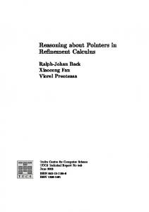
(a) A square root system.
(b) Incompatibility detected.
Fig. 5: A system in RCRS Isabelle and detection of incompatibility. shown below (to import the RCRS Isabelle theories, and to declare the collection of theorems and lemmas that we will use later for simplification): theory RCRS_Demo imports "Isabelle/Simulink/SimplifyRCRS" begin named_theorems basic_simps lemmas [basic_simps] = simulink_simps end
We next define three RCRS components (Fig. 5a): SqrRoot (modeling the square root function, see Section 2), Const1 (modeling the constant 1), and the composite component Syst1, formed by composing Const1 and SqrRoot in series. We explain the notation and point out that SqrRoot is non-inputreceptive, meaning that it rejects negative inputs. The simplify RCRS construct does several things. First, it defines the composite component Syst1. Second, it gives names to the external inputs and outputs of Syst1: "u" and "y" in this case. Third, it calls the RCRS Analyzer. The Analyzer is a set of procedures that we implemented on top of Isabelle, to perform a number of static analysis tasks. Among these tasks are the expansion and simplification of the logical formulas involved in RCRS expressions like the ones here. In this example, the Analyzer finds that Syst1 simplifies to [- u ; 1 -], as shown at the bottom of the Isabelle window, in the frame called “Output”. This result is to be expected, as the whole system outputs the constant 1. Let us now see what happens if we replace the constant 1 by −1. As we can see (Fig. 5b), the Analyzer now returns ⊥. In RCRS ⊥ models the invalid component, and the fact that a system simplifies to ⊥ indicates some kind of inconsistency. The inconsistency here is obviously that −1 violates the input condition of SqrRoot. So the components Const2 and SqrRoot are incompatible. So far, all our components were deterministic systems, in the sense they map each input to a unique output. Let us continue our example by showing what
happens if we try to connect SqrRoot to a non-deterministic component which can output any value. definition [basic_simps] : "true = [: u ; y::real. True]"
This component, called true, can be seen as modeling a “black-box” system for which we have no information (e.g., no available source code) or which we are unable to analyze. Obviously, in such a case, it is difficult to guarantee anything. Therefore, connecting true to SqrRoot should result in an incompatibility. Indeed, when we call the Analyzer’s simplification procedure: simplify_RCRS "Syst3 = true thm Syst3_simp
o
SqrRoot" "u" "y"
we see in Isabelle’s output window that the system simplifies to Syst3 = {.u. ∀y. 0 ≤ y.}
[: u ; y. ∃z. y = sqrt z:]
o
The formula ∀y.0 ≤ y is unsatisfiable, which means that Syst3 is inconsistent, indicating the incompatibility. Unfortunately, the simplification above does not result in an expression which is as simple as it can be, which is due to Isabelle’s limitations in simplifying expressions with quantifiers. In this case we have to “help” Isabelle, by recognizing that the formula ∀y.0 ≤ y is unsatisfiable. We state this as a lemma: lemma aux1: "(∀y::real. 0 ≤ y) = False" (* sledgehammer *) using le_minus_one_simps(3) by blast
and prove it using Isabelle’s “sledgehammer” mechanism (strangely, Isabelle’s “auto” does not work on this formula, even though it appears to work on the more complex formula discussed below). Having proved this lemma, we can call the simplification procedure again and ask it this time to use the lemma as a fact: simplify_RCRS "Syst4 = true use (aux1)
o
SqrRoot" "u" "y"
This time simplification succeeds and produces: Syst4 = ⊥
Now, suppose that we have a component for which we know something, for instance, that its output y is greater than its input x plus 1: definition [basic_simps]: "A = [: x ; y. y≥x+1 :]"
Let us see what happens if we connect A to SqrRoot, and try to simplify: simplify_RCRS "Syst5 = A
o
SqrRoot" "x" "y"
We get: Syst5 = {.x.∀y≥x+1. 0≤y.}
o
[:x;y.∃z≥x+1. y=sqrt z:]
Again, Isabelle has trouble eliminating the quantifiers from the formulas and needs our help. We recognize that the formula in the precondition is equivalent to x ≥ −1, and state this as a lemma: lemma aux2: "(∀y::real≥x + 1. 0≤y) = (x≥-1)" by auto
(Interestingly, Isabelle manages to prove this result automatically, even though the formula involved seems more complex than the unsatisfiable formula above.) We can now use the above lemma to simplify further: simplify_RCRS "Syst6 = A use (aux2)
o
SqrRoot" "x" "y"
and we get: Syst6= {.x. -1 ≤ x.}
o
[:x;y.∃z≥x+1. y=sqrt z:]
The precondition x ≥ −1 is as simple as it can be, but the postcondition can be simplified further by eliminating the existential quantifier. This requires manual intervention to Isabelle which will be explained in the demo. The end result is the following lemma lemma "Syst6 = {. x. -1 ≤ x .} apply ...
o
[: x ; z. z ≥ sqrt (x+1)]"
which depends on proving lemma aux3: "(λ x z. -1≤x ∧ (∃y. y≥(x+1) ∧ z = sqrt y)) = (λ x z. -1≤x ∧ z ≥ sqrt (x+1))" apply ...
These proofs will be included in the software artifacts and details will be provided during the demonstration. The above examples illustrated several of the features of RCRS as a reasoning tool, similar to a behavioral type checking and inference engine. Indeed, detecting incompatible connections is akin to catching type errors in programs, and inferring conditions such as the condition on the input in the last example above is akin to type inference. In addition to these capabilities, RCRS can be used to check refinement (and its counterpart, abstraction) between components. We next show how to prove that SqrRoot refines NonDetSqrt and that ReceptiveSqrt refines SqrRoot (NonDetSqrt and ReceptiveSqrt are defined in Section 2). We have: lemmas [basic_simps] = comp_rel_simps basic_block_rel_simps update_def refinement_simps definition [basic_simps] : "NonDetSqrt = {.x.x≥0.} o [: x ; y. y≥0 :]" lemma "NonDetSqrt ≤ SqrRoot" by (auto simp add: basic_simps) definition [basic_simps] : "ReceptiveSqrt = [: x;y. x≥0 → y=sqrt x:]" lemma "SqrRoot ≤ ReceptiveSqrt" by (simp add: basic_simps)
The first line instructs the Analyzer to use simplification rules for relational predicate transformers [11]. Then, we define the new components and state the refinements as lemmas. The proofs are simple and are based on the necessary and sufficient conditions for checking refinement included in the RCRS library: lemma assert_demonic_refinement: "({.p.} o [:r:] ≤ {.p’.} = (p ≤ p’ ∧ (∀ x . p x → r’ x ≤ r x))" by (auto simp add: le_fun_def assert_def demonic_def)
o
[:r’:])
1
In
u
Sqrt
1
Out
(a) A Simulink diagram
(b) Running the translator on the Simulink diagram above (c) The generated RCRS theory
Fig. 6: Applying the RCRS toolchain on a Simulink diagram. lemma spec_demonic_refinement: "({.p.} o [:r:] ≤ [:r’:]) = (∀x. p x → r’ x ≤ r x)" by (auto simp add: le_fun_def assert_def demonic_def)
A.2
The Simulink Translator
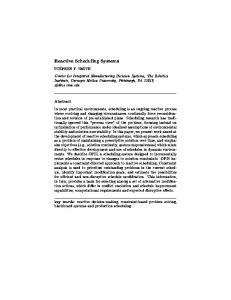
The RCRS toolset also contains a Translator which takes as input Simulink diagrams (.slx files) and generates RCRS Isabelle theories (.thy files). The Translator is a Python program called simulink2isabelle. We illustrate its use by building a simple Simulink model (Fig. 6a) and using simulink2isabelle to translate it to RCRS: ./simulink2isabelle.py sqrt_syst.slx -ic
The execution of the translator is shown in Fig. 6b, and the generated RCRS Isabelle theory is rendered in Fig. 6c. The option -ic tells the Translator to use a specific algorithm for translating block diagrams to composite RCRS components. Here we pause and introduce another feature of RCRS which we haven’t talked about so far, namely, its composition operators. RCRS offers three primitive composition operators: serial (which we have already seen), parallel, and feedback. We will illustrate the latter two with examples coming from Simulink. Before doing so, let us go over the file sqrt syst.thy generated by the Translator. The structure of the file is similar to the files we have manually created earlier. One difference is that the definition of the basic components, corresponding to basic Simulink blocks, refers to predefined RCRS components included in the Simulink.thy library. We can CTRL-click to see the definition of these com-
ponents: we CTRL-click on top of a component which opens automatically the Simulink.thy file. We explain briefly the Simulink.thy file, which contains the RCRS formalization of several Simulink basic blocks. For example, the Gain block definition "Gain k = [- x ; x * k -]"
is parameterized by k, the multiplication factor. The Integrator block definition "Integrator dt = [- x, s ; s, s+x*dt -]"
is parameterized by dt, the time step of the simple Euler integration method that we use. Here we take also the opportunity to explain how we model in RCRS stateful components: s is the state variable in the Integrator component above. In all our examples so far we have seen only serial composition, o . RCRS contains three primitive composition operators: serial, parallel, and feedback, which we illustrate in the sequel. Consider the Simulink diagram of Fig. 7. We execute the Translator ./simulink2isabelle.py simple_syst.slx -ic
and obtain a theory where Model SqrRoot, Model Add and Model UnitDelay are defined respectively as SqrRoot, Add and UnitDelay above, and the toplevel system is defined as shown below: simplify_RCRS "IC_Model = feedback ([- b, f, si_j ; (f, b), si_j -] ◦ (Model_In ** Model_Sqrt ◦ Model_Add) ** Skip ◦ Model_UnitDelay ◦ Model_Split6 ** Skip ◦ [- (a, b), so_j ; b, a, so_j -]) ◦ Model_Out ** Skip" "(f, si_j)" "(h, so_j)"
The parallel and feedback composition operators are denoted ** and feedback. ** binds stronger than o , so that A ** B o C is equivalent to (A ** B) o C. Skip is identical to Id. The current and next state variables are denoted si j and so j. 1
In
1 z
u
Add
Unit Delay
1
Out
Sqrt
Fig. 7: Simulink model simple syst.slx.
A.3
An Industrial Benchmark
We apply the entire toolset on the Toyota Simulink model briefly discussed in Section 6 (part of the model is shown in Fig. 8). First we run the translator: ./simulink2isabelle.py afcs.slx -const -type real -iter -sim
Fuel Control System Model
This model uses only the ODEs to implement the dynamics.
theta [0 90] 1 throttle input (deg) [0, 81.2]
1 .1s+1
1 A/F
Throttle delay1 f(u)
1 s
ODE1
p
8.8 Base opening angle
f(u)
1 s
ODE2
lambda
f(u)
1 s
ODE3
12.5
~=
f(u) ODE4 Closed
2 airbyfuel_ref
pe
~=
Fuel Cmd Open Pwr f(u)
0.0 ODE4 Open
double
14.7
f(u)
~=
Fuel Cmd Open
1 s
~=
i f(u) Fuel Cmd Closed
f(u) InputPoly
2 engine speed (rpm) [900,1100]
pi/30
AND
(rpm) to (rad/s)
Power Mode Guard boolean Starup Mode
1: Failure 0: Normal
Out
Startup Mode Latch
boolean FaultInjection
In
In
Out
Sensor Failure Detection Latch
OR
3 controller_mode NOT
Powertrain Control Benchmark Model Toyota Technial Center 2014 This is a model of a hybrid automaton with polynomial dynamics, and an implementation of the 3rd model that appears in "Powertrain Control Verification Benchmark", 2014 Hybrid Systems: Computation and Control, X. Jin, J. V. Deshmukh, J.Kapinski, K. Ueda, and K. Butts
Fig. 8: Excerpt of the Toyota Fuel Control System Simulink model. Option -iter generates code that represents the behavior of the system over time, and option -sim generates a Python simulation script.
Fig. 9: The simplified predicate transformer of the Fuel Control System. The resulting file afcs.thy is quite long and its processing by Isabelle takes about 15 seconds. The Analyzer detects no incompatibilities and computes a simplified top-level atomic component whose description is 8338 characters long (an excerpt is shown in Fig. 9). We explain this top-level component, which has a non-trivial automatically generated state condition. Then we run the generated Python simulation code, compare the simulation trajectories with those of Simulink, and find that they are essentially identical.