Antennal flexure. C44. Standing jump. 20. 40. 60. 80. Pulses/sec. D11. Foraging. C63. Antennal flexion. 100. 24 r .16. 3 8. C 49. Locomotion. D 1 . Standing jump.
J. Exp. Biol. (1963), 40, 15-21 With 5 text-figures Printed in Great Britain
jc
THE RELATION BETWEEN STIMULUS PARAMETERS AND CURRENT FLOW THROUGH STIMULATING ELECTRODES BY C. H. FRASER ROWELL Department of Zoology, Cambridge University* (Received 19 August 1962) INTRODUCTION
During electrical stimulation of the insect brain with chronically implanted electrodes, measurements have been made of the thresholds of behavioural responses. These thresholds are in terms of the voltage across, or the current through, the preparation as measured by the usual type of monitoring circuit. When pulse length and amplitude are constant, the threshold commonly varies with the pulse repetition rate (p.r.r.) of rectangular stimulating pulses, especially over the D 11. Antennal flexure 30
24 r D11. Foraging
20
.16
C63.
10
Antennal flexion
C 49. Locomotion
3 8
D 1 . Standing jump
C44. Standing jump 20
40 60 Pulses/sec.
80
100
20
40
60
80
100
Pulses/sec.
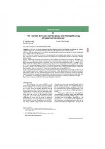
Fig. 1. Typical variations in thresholds of behavioural responses to electrical stimulation of the brain in Schistocerca with different pulse repetition rates, (a) Thresholds measured in terms of current through insect by a measuring circuit similar to that of Fig. z, but without isolation units, (b) Thresholds measured in terms of latency of response. Stimulus parameters other than pulse repetition rate constant throughout.
range 10 to ioo pulses/sec. (Fig. i.) Most frequently the threshold falls with increasing p.r.r.; responsiveness to one particular frequency also occurs, and also rising threshold with increasing p.r.r., though this last could easily be due to fatigue. Similar results have been reported by many previous workers with cerebral electrodes from both • Present Address: Department of Zoology, Makerere University College, Kampala, Uganda.
i6
C. H. FRASER ROWELL
vertebrate and invertebrate material, and have also been found in studies in which stimulation and recording from nerves took place through external hook electrodes. An investigation was made to see whether this was necessarily a characteristic of the biological system, or whether artifacts were present in the form of changes in the physical conditions of stimulation. The results suggest that the latter is true. METHOD
Negative rectangular pulses with a rise time of less than 10 /xsec. and a duration of about i msec, were applied from a stimulator of low output impedance. The stimulator had a considerable capacitance to earth, and for critical measurements it was necessary to isolate it, not only from the preparation but from the whole measuring circuit, by
Fig. 2. Experimental arrangement required to measure true current through and potential difference across, a load L connected to a square wave stimulator. The i M. resistor Rr increases the input resistance of the Y2 channel of the oscilloscope, decreasing the shunt across the load L. The oscilloscope is triggered before the stimulus in order that the initial part of the wave-form may be seen. Further explanation in text.
means of an R.F. head. The voltage across, and the current through, the load L were measured as shown in Fig. 2. The measuring resistor Rm must be small compared to the impedance of the load to avoid a significant reduction of the initial pulse voltage across the load. Component values were arranged so that the input impedances and capacitances of the oscilloscopes did not significantly affect the measurements. The load was (a) a passive RC network, (b) electrodes dipped in saline or water, or (c) an insect. In the last case the stimulating electrode was of insulated stainless-steel wire 2011 in diameter, presenting a surface of approximately 3 x io~4mm.2, and the indifferent electrode was of stainless-steel wire and of comparatively large surface, about 3 mm.2. The electrode was implanted in the brain by a method to be described elsewhere (Rowell, unpublished.)
Relation between stimulus parameters and current flow RESULTS
The current wave-form seen when a single pulse is applied to the brain is complex, and varies with the size of the electrodes and the impedance of the preparation, but the most important elements produced by the electrodes described are shown in Fig. 3. An identical wave-form is seen if the same electrodes are placed in a saline of the same impedance as the preparation. The wave-form closely resembles that produced by the passive network shown in Fig. 3. An exact circuit analogue would, however, be much more complex, as the observed wave-form shows non-linear change with almost every parameter, and it is probably unsafe to identify any parts of the analogue with parts of the actual system. The initial current spike, equivalent to the parallel capacitance Cp, 30 r
1000PpF.
20
C 2000 pF. 10
270 K.
250
750
1250 /&.