The rendering context for stereoscopic 3D web Qinshui Chen, Wenmin Wang*, Ronggang Wang School of Electronic and Computer Engineering, Shenzhen Graduate School, Peking University, Lishui Road 2199, Nanshan District, Shenzhen, 518055 China ABSTRACT 3D technologies on the Web has been studied for many years, but they are basically monoscopic 3D. With the stereoscopic technology gradually maturing, we are researching to integrate the binocular 3D technology into the Web, creating a stereoscopic 3D browser that will provide users with a brand new experience of human-computer interaction. In this paper, we propose a novel approach to apply stereoscopy technologies to the CSS3 3D Transforms. Under our model, each element can create or participate in a stereoscopic 3D rendering context, in which 3D Transforms such as scaling, translation and rotation, can be applied and be perceived in a truly 3D space. We first discuss the underlying principles of stereoscopy. After that we discuss how these principles can be applied to the Web. A stereoscopic 3D browser with backward compatibility is also created for demonstration purposes. We take advantage of the open-source WebKit project, integrating the 3D display ability into the rendering engine of the web browser. For each 3D web page, our 3D browser will create two slightly different images, each representing the left-eye view and right-eye view, both to be combined on the 3D display to generate the illusion of depth. And as the result turns out, elements can be manipulated in a truly 3D space. Keywords: Stereoscopic, 3D, web, browser, WebKit, W3C, HTML, CSS, JavaScript
1. INTRODUCTION Stereoscopic 3D (S3D) is a technique for creating the illusion of depth in an image by means of stereopsis for binocular vision. It is based on the principle that human brain extracts the depth information and perceives the stereoscopic views by fusing together the two images acquired by left- and right-eye. In the recent years, the display industry is witnessing a major change from 2D to realistic 3D as evidenced by the success of recent 3D movies and consumer 3DTV product offerings. It can be envisioned that within the next few years a major share of current displays will be replaced by 3D displays or at least by 3D-capable displays, and stereoscopic and autostereoscopic technologies are likely to play a major role [1]. Research on 3D on the Web have long been investigated, with popular solutions like VRML, X3D, WebGL and O3D et al [2]. However, these technologies mainly fall into the category of monoscopic 3D (M3D) – traditional 3D computer graphics that create images based on a 3D coordinate system and then display these images onto a monoscopic 2D device. With the stereoscopic technology gradually maturing, what we have been doing since the beginning of 2011 is to apply stereoscopy to the Web based on binocular parallax theory [3]. In late 2012, the World Wide Web Consortium (W3C) also published an Editor’s Draft to provide extensions for Stereoscopic 3D support [4]. In this paper we will introduce some new CSS properties, so that elements can be manipulated and be perceived in a truly 3D space. We have also implemented stereoscopic 3D browser that are compatible with existing 2D web pages, and examples with HTML source code fragments are also displayed.
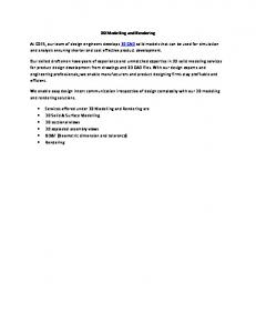
2. UNDERLYING PRINCIPLES 2.1 Binocular parallax Human bran’s ability to appreciate a third dimension using a 3D display is based on the characteristics of the human visual system. Since the eyes are positioned horizontally in the head, the visual system receives two views of the visual scene, i.e., the left-eye and right-eye views, which largely overlap but differ slightly because they originate from two *
[email protected]; phone 86 755 2603-5700; fax 86 755 2603-2100; ece.pku.edu.cn Stereoscopic Displays and Applications XXV, edited by Andrew J. Woods, Nicolas S. Holliman, Gregg E. Favalora, Proc. of SPIE-IS&T Electronic Imaging, SPIE Vol. 9011, 90111P · © 2014 SPIE-IS&T CCC code: 0277-786X/14/$18 · doi: 10.1117/12.2038828 SPIE-IS&T/ Vol. 9011 90111P-1 Downloaded From: http://proceedings.spiedigitallibrary.org/ on 03/06/2014 Terms of Use: http://spiedl.org/terms
different perspectives (Figure 1(a)). The visual system processes the information from the two images originating from two perspectives to produce stereoscopic depth. The same object in the scene will have different relative positions in the two views. The difference in relative position is typically called parallax, which can be divided into three classes – positive parallax, zero parallax and negative parallax. When displayed stereoscopically, those objects with zero parallax will be depicted at the screen plane, while those with negative or positive parallax will appear in front of or behind the screen plane (Figure 1(b)). positive parallax
(a)
(b)
depth zero parallax left eye
stereo plane
right eye
negative parallax left view
right view
Figure 1. Principles of stereoscopic 3D. (a) Binocular views. (b) Three types of horizontal parallax.
2.2 From object space to image space This section will demonstrate the mathematical relationships between objects as how they are perceived in the threedimensional space (object space) by the brain of the viewer and how they are drawn in the left-eye and right-eye images (image space). Every stereoscopic web page requires two images – the left- and right-eye perspective views. There are two basic approaches to computing the left- and right-eye perspective views of a stereoscopic image. The two approaches are mathematically identical but produce slightly different images in practice. We refer to the two approaches as the off-axis projection and the on-axis projection [5]. The off-axis projection assumes two different, horizontally aligned centers of projection. The right-eye view will be produced by projection to a right center of projection, and the left-eye view will be produced by projection to a left center of projection. Both projections are implemented in conjunction with a standard viewing transformation. The drawback of this approach is that few graphics workstations provide hardware graphics routines that allow programmer control of the center of projection. Whereas an off-axis projection is accomplished by moving the center of projection, the on-axis projection produces the same set of projected points by using a single center of projection in conjunction with horizontal translations of the data. It can take advantage of the standard perspective projection. Actually, this is also the approach adopted by the W3C Working Draft “CSS Transforms Module Level 1” [6], in which the CSS Transforms are used to compute the internal perspective matrix from the ‘perspective’ and ‘perspective-origin’ properties. Our paper will adapt the on-axis projection mentioned in [5] to the coordinate system used by the CSS 3D Transforms, and apply it to the rendering context in S3D Web. Assume a scene in which the observer looks right into the center of the view port. The coordinate space used by CSS 3D transform is a coordinate system with three axes: the X axis increases horizontally to the right; the Y axis increases
SPIE-IS&T/ Vol. 9011 90111P-2 Downloaded From: http://proceedings.spiedigitallibrary.org/ on 03/06/2014 Terms of Use: http://spiedl.org/terms
vertically downwards; and the Z axis increases towards the viewer. For the sake of compatibility, we use the same coordinate system to describe stereoscopic elements (Figure 2). For an arbitrary point P = (X,Y,Z,1)T in the object space, mark Pl = (Xl,Yl,Zl,1)T and Pr = (Xr,Yr,Zr,1)T as points in the left- and right-eye image spaces (corresponding projected points for the left- and right-eye images). The projection plane coordinates for Pl:
P(X,Y,Z)
.-_,.
Pr(Xr, Pl(X1,Y1,Z1)
+y axis
Figure 2. Demonstration of the coordinate space for stereoscopic 3D Web
e V(X ) 2 e, Xl V Z 2
Yl
YV V Z
(1)
e V(X ) 2 e, Xr V Z 2
Yr
YV V Z
(2)
and for Pr:
Now we can compute the horizontal screen parallax for this point, which can be calculated from the difference of the projected X-coordinates:
p Xr Xl
eZ V Z
(3)
A more explicit explanation of Equation 1 and 2 is that, for an arbitrary point P in the object space, its coordinate values in the image spaces can be obtained by 1.
Translation of x by +e/2 (-e/2 for the right-eye image).
2.
Standard perspective projection.
3.
Translation of the projected x by -e/2 (+e/2 for the right-eye image).
The standard perspective projection in Step 2 is equivalent to the perspective projection matrix described in [6]:
1 0 M = 0 0
0 1 0
0
0 1 1 0 V
0 0 0 1
SPIE-IS&T/ Vol. 9011 90111P-3 Downloaded From: http://proceedings.spiedigitallibrary.org/ on 03/06/2014 Terms of Use: http://spiedl.org/terms
(4)
where the V parameter is the computed value of the ‘perspective’ property. Accomplished the on-axis projection requires the value of the e parameter. In [4] this value is computed from the ‘perspective-baseline’ property, whereas we use an ‘eye-distance’ property. Integrate the on-axis projection for stereoscopic views into the CSS 3D Transforms will internally affect the computing of the CSS perspective matrix. The single perspective matrix now turns into two-eye perspective matrices. Steps in [6] that computing the perspective matrix are now modified as follows: 1) Start with the identity matrix. 2) Translate by the computed X and Y values of ‘perspective-origin’ and ‘eye-distance’. 3) Multiply by the matrix that would be obtained from the ‘perspective()’ transform function, where the length is provided by the value of the ‘perspective’ property. 4) Translate by the negated computed X and Y values of ‘perspective-origin’ and ‘eye-distance’. In the above steps, how X and Y values are computed from ‘perspective-origin’ and ‘eye-distance’ is different between the left- and right-eye views. If Xp and Yp are the values of ‘perspective-origin’, e is the value of ‘eye-distance’, for the left-eye view:
e X Xp , 2
Y=Yp
(5)
e X Xp , 2
Y=Yp
(6)
for the right-eye view:
3. TRANSFORMS FOR S3D WEB 3.1 S3D-CSS In this section we will extend the CSS Transforms [6] for stereoscopic support by introducing some new properties. These newly invented properties, together with the original CSS properties, constitutes a superset (S3D-CSS) of current CSS standard (Table 1). The ‘eye-distance’ property functions much like the ‘perspective-baseline’ property in [4]. It applies to all elements because we allow any element to turn into a stereoscopic element. It is also used to compute the e parameter in Section 2. The ‘eye-distance’ can work together with the ‘perspective’ property to project 3D elements onto the screen as a stereoscopic image. When a ‘perspective’ is applied, only one perspective matrix is computed and the element is painted as a M3D image (Figure 3(a)); when both ‘eye-distance’ and ‘perspective’ are applied, the left- and right-eye image will have their own perspective matrix, and the element is rendered to the two-eye views using different projections. When these two views are combined on a stereoscopic 3D screen, the element can be perceived in a truly 3D space (Figure 3(b)). The ‘depth’ property is specified in units of the view volume (the V parameter) and should be assigned with a value between -1 and +1.
Table 1. CSS-S3D properties for stereoscopic 3D Transforms.
Name
Value
Initial
eye-distance
none |
none
depth
0
Applies to
Inherited
Percentage
all elements
no
N/A
visual
Absolute “none”
all elements
no
N/A
visual
Absolute length between -1 and +1
SPIE-IS&T/ Vol. 9011 90111P-4 Downloaded From: http://proceedings.spiedigitallibrary.org/ on 03/06/2014 Terms of Use: http://spiedl.org/terms
Media
Computed value length
or
div { height: 150px; width: 150px; border: 1px solid black; } .container { -webkit-perspective:150; } .projected { background-color: yellow; -webkit-transform: rotateX(45deg); }
div { height: 150px; width: 150px; border: 1px solid black; } .container { -webkit-perspective:150; eye-distance: 50; } .projected { background-color: yellow; -webkit-transform: rotateX(45deg); }
(a)
(b)
HELLO
Figure 3. The ‘perspective’ and ‘eye-distance’ properties. (a) The element is projected as a M3D image when only ‘perspective’ is applied. (b) With both ‘perspective’ and ‘eye-distance’, the element is projected as a S3D image. 3.2 S3D transform rendering Normally, the elements render as flat planes, and are rendered into the same plane as their containing block. When Transforms are applied, elements won’t interact with each other and painting orders are not affected. In other words, Transforms are like a painting effect. For example, a transform with a positive Z translation may make an element look larger, but doesn’t cause that element to render in front of elements with no translation in Z. However, when contained in a 3D rendering context, all elements can visibly interact with other elements in that same 3D rendering context; the set of elements participating in the same 3D rendering context may obscure each other or intersect, based on their computed Transforms. They are rendered as if they are all siblings, positioned in a common 3D coordinate space. The position of each element in that three-dimensional space is determined by accumulating the transformation matrices up from the element that establishes the 3D rendering context through each element that is a containing block for the given element [6]. Using ‘perspective’ alone, we can project a 3D rendering context as a M3D image onto the page view (Figure 4(a)); using ‘perspective’ together with ‘eye-distance’, we can create a S3D view for this rendering context -- when painting the left-eye view, we use the left-eye perspective matrix to project the rendering context; otherwise we use the right-eye perspective matrix (Figure 4(b)).
SPIE-IS&T/ Vol. 9011 90111P-5 Downloaded From: http://proceedings.spiedigitallibrary.org/ on 03/06/2014 Terms of Use: http://spiedl.org/terms
div { height: 150px; width: 150px; } .container { -webkit-perspective: 500px; border: 1px solid black; } .transformed { -webkit-transform-style: preserve-3d; -webkit-transform: rotateY(50deg); background-color: blue; } .child { -webkit-transform-origin: top left; -webkit-transform: rotateX(40deg); background-color: lime; }
div { height: 150px; width: 150px; } .container { -webkit-perspective: 500px; eye-distance: 50; border: 1px solid black; } .transformed { -webkit-transform-style: preserve-3d; -webkit-transform: rotateY(50deg); background-color: blue; } .child { -webkit-transform-origin: top left; -webkit-transform: rotateX(40deg); background-color: lime; }
(b)
Figure 4. 3D rendering context. (a) The context is projected as a M3D image when only ‘perspective’ is applied. (b) With both ‘perspective’ and ‘eye-distance’, the context is projected as a S3D image
3.3 Image scaling Throughout the procedure of page rendering, the left- and right-eye views are computed assuming that the observer is located in a fixed distance from the projection plane, and this distance is not dynamically changed as the viewer changes his head position. This assumption results in a fixed horizontal parallax for points at a particular distance from the projection plane regardless of the position of the viewer. The fixed horizontal parallax causes distortion of the image along the viewing axis normal to the plane of the viewer as shown in figure 5. As the observer moves away from the display, the image is elongated. As the viewer moves closer, the image contracts. As the observer shifts his head from side-to-side, the same view of the image shifts in conjunction with his head movement. The practical implication of these factors is that there is an optimal position at which to view the stereoscopic image so that the front-to-back scaling of the image is in correct proportion to the up-down and left-to-right scaling [5]. Therefore, in order to produce a desired S3D view, ‘eye-distance’ and ‘perspective’ must be set to appropriate values, and the observer must appear at the optimal position.
SPIE-IS&T/ Vol. 9011 90111P-6 Downloaded From: http://proceedings.spiedigitallibrary.org/ on 03/06/2014 Terms of Use: http://spiedl.org/terms
stereo plane Perceived Point
From Position 2
Perceived Point
Observer
Observer
Position 2
Position 1
From Position 1
Figure 5. Distortion caused by head movement and no parallax change.
4. IMPLEMENTATION WebKit is a layout engine software component designed to allow web browsers to render web pages, powering famous browsers like Google’s Chrome and Apple’s Safari [7]. Corresponding browser engines includes the Gecko (used by Mozilla Firefox) and Trident (used by Microsoft IE). We adopt WebKit for its notable features such as being opensource, high speed, less memory, etc. The main flow of WebKit mainly includes HTML/CSS parsing, DOM tree constructing, render tree constructing and painting [8]. Adding HTML-S3D tags and CSS-S3D properties to WebKit doesn’t have to change its original working flow. The most important change we made to WebKit is a re-painting procedure. As mentioned in Section 2, two visible frames must be rendered for a single stereoscopic 3D web page. Therefore, we create two frame buffers for the rendering process. The original rendering flow of WebKit will paint the web page in the left-eye frame buffer. After that we move each element horizontally according to its screen parallax computed from Equation 3. The adjusted page is painted in the right-eye frame buffer. Finally, these two frame buffers are combined on the 3D screen.
ACKNOWLEDGEMENTS This project was supported by Shenzhen Foundation for Basic Research (JC201104210117A, JCYJ20120614150236998), by Shenzhen Engineering Lab on Intelligent Perception for Internet of Things, and by Shenzhen Engineering Lab of Three-dimensional Media Technology.
REFERENCES [1] Urey, H., Chellappan, K. V., Erden, E. and Surman, P., "State of the art in stereoscopic and autostereoscopic displays," Proceedings of the IEEE, 99(4), 540-555 (2011). [2] Ortiz, S., “Is 3d finally ready for the web?” Computer, 43 (1), 14-16 (2010). [3] Wang, W., Wang, X., Gao, W. and Liang, F., “An Implementation of 3D Web Browser based on Binocular Parallax Theory,” China Patent, ZL201110131554.1, May 20, 2011. [4] W3C, “Extensions for Stereoscopic 3D support,” 30 November 2012, http://www.w3.org/2011/webtv/3dweb/3dweb_proposal_121130.html. [5] Hodges, L. F., "Basic principles of stereographic software development," In Electronic Imaging'91, San Jose, CA, International Society for Optics and Photonics, 9-17 (1991). [6] W3C, “CSS Transforms Module Level 1,” 26 November 2013, http://www.w3.org/TR/css3-transforms/. [7] The WebKit Open Project. http://www.webkit.org/. [8] Tali, G. and Paul, I., "How Browsers Work: Behind the scenes of modern web browsers," http://www.html5rocks.com/en/tutorials/internals/howbrowserswork.
SPIE-IS&T/ Vol. 9011 90111P-7 Downloaded From: http://proceedings.spiedigitallibrary.org/ on 03/06/2014 Terms of Use: http://spiedl.org/terms