... implementations also exist, such as Rice University TAPS in Houston [14] and ..... to be performed (e.g., Cisco Systems cards report a maximum RSSI value of ...
The SMesh Wireless Mesh Network Yair Amir1 , Claudiu Danilov2 , Raluca Mus˘aloiu-Elefteri1 , Nilo Rivera1 1 Johns Hopkins University 2 Boeing Phantom Works Technical Report CNDS-2009-3 - April 2009 http://www.dsn.jhu.edu
Abstract Wireless mesh networks extend the connectivity range of mobile devices by using multiple access points, some of them connected to the Internet, to create a mesh topology and forward packets over multiple wireless hops. However, the quality of service provided by the mesh is impaired by the delays and disconnections caused by handoffs, as clients move within the area covered by multiple access points. We present the architecture and protocols of SMesh, the first transparent wireless mesh system that offers seamless, fast handoff, supporting real-time applications such as interactive VoIP. The handoff and routing logic is done solely by the access points, and therefore connectivity is attainable by any 802.11 device. In SMesh, the entire mesh network is seen by the mobile clients as a single, omnipresent access point, giving the mobile clients the illusion that they are stationary. We use multicast for access points coordination and, during handoff transitions, we use more than one access point to handle the moving client. SMesh provides a hybrid routing protocol that optimizes routes over wireless and wired links in a multi-homed environment. Experimental results on a fully deployed mesh network demonstrate the effectiveness of the SMesh architecture and its intra-domain and inter-domain handoff protocols.
1
Introduction
Wireless networks have changed the way people connect to the Internet, giving users the freedom to connect from anywhere within the coverage are of a wireless access point. Wireless Mesh Networks extend the wireless coverage area of an access point by having a few access points connected to a wired network, and allowing the others to forward packets over multiple wireless hops. A mesh network can span a large geographical area. Internet connected access points (Internet gateways) may reside at different network domains, effectively creating a multi-homed wireless mesh network. When a user moves outside the range of an access point and closer to another, it switches its connectivity to the closer access point. This connectivity change involves a transition (handoff ) before being able to route packets to and from the new access point. Maintaining connectivity requires a handoff at two levels. An intra-domain handoff is required to transfer connectivity between the access points serving the mobile device. At a higher level, an inter-domain handoff between access points connected to the Internet may be required on existing connections. Both handoffs, which can occur simultaneously, must maintain all previously opened connections while transferring them as fast as possible. Ideally, the handoff should be completely transparent to mobile clients. There should be no interruption in network connectivity, and the communication protocols involved should follow the standards deployed in regular wireless devices. We call a wireless network that
1
offers such a service a seamless wireless mesh network. While cell phone networks solve the handoff problem using signaling embedded in their lowlevel protocols [9, 17], there are currently no efficient, transparent handoff solutions for wireless 802.11 networks. Most wireless networks today require specially modified clients in order to transfer connectivity from one access point to the next. Others, even if they give the appearance of continuous connectivity to a roaming client, provide connections that are in fact interrupted when a client transfers from one access point to the next, with delays that can be as long as several seconds [33, 48]. For some applications (e.g., transferring files), this delay may be acceptable (although it will lower the overall throughput). However, it is far too long for real-time traffic such as interactive Voice over IP or video conferencing. This paper presents the architecture and protocols of SMesh [6, 7], the first transparent wireless mesh network that offers seamless fast handoff, supporting VoIP and other real-time application traffic. The entire handoff and routing logic is done solely by the access points, and therefore connectivity is attainable by any 802.11 mobile device, regardless of its vendor or architecture. In order to provide this level of transparency to mobile clients, our approach uses only standard network protocols. The entire mesh network is seen by the mobile clients as a single, omnipresent access point, giving the mobile clients the illusion that they are stationary. Mobile clients are handled by a single access point during stable connectivity times. Fast intradomain handoff is achieved by controlling the handoff from the mesh infrastructure and by using multicast in the mesh network to send data through multiple paths to the mobile client during handoff. Access points continuously monitor the connectivity quality of any client in their vicinity and efficiently share this information with other access points in the vicinity of that client to coordinate which of them should serve the client. If multiple access points believe they have the best connectivity to a mobile client, and until they synchronize on which should be the one to handle that client, data packets from the Internet gateway (or another source within the mesh network) to the client are duplicated by the system in the client’s vicinity. Fast inter-domain handoff is achieved by using multicast groups through the wired network to coordinate decisions and seamlessly transfer connections between Internet gateways as mobile clients move between access points. New connections always use the closest Internet gateway at the time of their creation, while existing connections are forwarded through the wired infrastructure to the Internet gateway where they were originally initiated. As the handoff process requires routing agreement and transferring connections between the involved Internet gateways, our protocol guarantees that packets are routed correctly, at all times. While duplicating packets and tightly coordinating the access points in a client’s vicinity may seem to incur high overhead, this paper quantifies the overhead and demonstrates it is negligible compared to data traffic. We also show how our system optimizes peer-to-peer communication between mobile clients, utilizing the wired connectivity available at the Internet gateways to reduce wireless usage. The forwarding and coordination between the access points is done using our Spines messaging system [43] that provides efficient unicast, anycast, and multicast communication in an overlay network environment. The contributions of this paper are: 1. The architecture and protocols of the first seamless wireless mesh network with fast intradomain and inter-domain handoffs that support real-time applications such as interactive VoIP and video conferencing. 2. Novel use of multicast for robust mesh Internet gateway to client communication, as well as for access point coordination. 3. Novel use of anycast for mobile client to mesh Internet gateway communication.
2
4. A hybrid routing protocol for mesh communication that optimizes routes over wireless and wired links in a multi-homed environment. 5. A set of experiments in a real-world deployment demonstrating the effectiveness of the SMesh system. The rest of the paper is organized as follows: The next section overviews related work, followed in Section 3 by a description of a generic wireless mesh network environment. Section 4 presents the architecture of our wireless mesh system, SMesh. Section 5 presents our fast intra-domain handoff protocol, which includes client monitoring, mobility management, and the fast handoff approach. In Section 6, we present our fast inter-domain handoff for multi-homed wireless mesh networks, showing how TCP and UDP connections are separately handled to correctly route these packets. We present experimental results in Section 7, and Section 8 summarizes our contribution and concludes the paper.
2
Related Work
Seamless mobility in wireless mesh networks must account for movement at two different levels: intra-domain, between access points, and inter-domain, between Internet connected access points potentially connected on different networks. As such, our work relates to previous work on wireless mesh networks, intra-domain handoff, and inter-domain handoff. In addition, our work relates to overlay networks, as the underlying communication infrastructure of SMesh relies on an overlay messaging system. Good surveys addressing most of these areas are provided by [3] and [2]. Note that related work may also refer to intra-domain handoff as micromobility and to inter-domain handoff as a form of macromobility.
2.1
Wireless Mesh Networks
One of the first commercial mesh networks was Metricom’s Ricochet network [44] in the mid-90s. Ricochet nodes automatically routed client traffic through half-duplex wireless hops until reaching a hardline connection. When the 802.11 standard was ratified in the late-90s, other mesh networks started to emerge. One of these is the MIT Roofnet project [16], [10] in which tens of access points with roof mounted antennas form a mesh around campus. Roofnet’s emphasis is more on route maintainability and optimization than on handing off a client’s connection. Many other community and commercial mesh network implementations also exist, such as Rice University TAPS in Houston [14] and UrbanaChampaign Community Wireless Project [20]. Microsoft Research has also done notable work in the area of mesh networks. Their Mesh Connectivity Layer (MCL) [23] creates a wireless mesh network between Windows clients. Their focus is on efficient routing protocols [24] along with the unique support for multiple radios on each node [1]. MCL requires a specific network driver on all mesh network participants, including the clients. [32] studied the throughput capacity of hybrid networks that connect some of the nodes through the wired network to improve efficiency in the use of the wireless spectrum. In our routing strategy we also take advantage of the wired connections available at the gateways. The IEEE 802.11s Mesh Networking standard, analyzed in [13], specifies three different types of mesh nodes. Mesh points (MP) includes all mesh nodes that participate in the wireless backbone to increase the mesh connectivity. Some mesh points serve as mesh access points (MAP), providing connectivity to clients within their wireless coverage area. Also, some mesh nodes may serve as mesh portals (MPP), connecting the wireless mesh to an external network such as the Internet. In our 3
approach, we assume that every node is potentially an access point, as it increases the availability of the system. Furthermore, other than Internet connectivity, we make no distinction between the capabilities available in nodes that are simply MAP, MPP, or both.
2.2
Intra-domain Handoff
Cell networks achieve smooth handoff by sharing information between towers about a given mobile device. This session data is used for routing and is updated whenever a phone switches cells [9], [17]. The 802.11 standard lacks the handoff mechanisms available in today’s cell network protocols. [33] analyzed the link-level handoff performance in current 802.11 hardware. Approximately 90% of a handoff delay is attributable to the client adapter scanning for its next AP. Their experiments also illustrate that the practical handoff delay can vary widely depending on the vendors used for the client network card and the AP. [47] investigated the latency effects of a wireless handoff on voice traffic. The conclusions echo those of Mishra et al. in that the handoff latency can vary widely depending on the hardware vendor used. Since our approach does not require re-association during handoff, we do not suffer from these vendor specific delays. [38] recently demonstrated that a quick link-level handoff is possible on 802.11 networks when the client monitors the signal quality of access points and uses a fast scanning mechanism to listen to all APs in range to choose the best one. Their SyncScan system has achieved an impressive handoff as low as 5 ms. The fast scanning is achieved through driver modifications of the client’s network adapter. In the contrary, our approach uses any unmodified 802.11 client. Two well known general approaches to intra-domain handoff in IP networks are Cellular IP [46] and Hawaii [39]. A comparison is presented in [15]. In Hawaii, or Handoff-Aware Wireless Access Internet Infrastructure, messages are exchanged between the old gateway and the new gateway for forwarding packets. Cellular IP establishes routes based on the traffic from the client, and handoff takes place when a cross-over router is reached. [12] use a different approach to mobility in which access points send gratuitous ARPs to their upstream routers to create the illusion that mobile clients are always connected to the wired network. These approaches rely on clients initiating the handoff process, and do not address the link level handoff delay present in 802.11 networks when clients reassociates with another access point. Other approaches to intra-domain handoff, such as TMIP [28], [49], and [41], improve handoff latency in 802.11 networks but do not overcome these limitations. Other general approaches such as IDMP [21], SMIP [31], and HMIP [29] focus on hierarchy to reduce the global signaling load and improve scalability. Most of the above require software be installed in the mobile clients. In contrast, we provide a complete link-level and network-level solution and propose a novel approach to seamlessly control the handoff from the infrastructure. Seshan, Balakrishnan, and Katz used a multicast approach in the Daedalus project [40] to ensure timely delivery of client traffic during a handoff in a cell-based wireless computer network available in 1996. Later, [30] show how fast handoff can be achieved in wireless networks by requiring mobile clients to explicitly join a multicast group to which packets are multicast-tunneled through the infrastructure. Multicast during handoff, referred to as simulcast, is also used during handoff in S-MIP [31]. Our approach also relies on multicast during handoff, but only in the mesh, to reach multiple access points, and therefore it does not require any modifications to the mobile client, thus supporting standard mobile devices of any architecture or operating system. The IEEE has also been working on standardizing handover for wireless IP networks at two different levels. The 802.11r standard aims at providing fast Basic Service Set (BSS) transition by allowing clients to use their current access point as a conduit to other access points. The 802.21 standard aims at providing handover between different network types, commonly known as media independent or vertical handover. These approaches require modifications to the 802.11 standard, and so to the access points and to every client device. In our approach, no modifications are necessary. Existing experimental wireless mesh testbeds that support client mobility include MeshCluster
4
[37] and iMesh [45], both of which work with mobile clients in infrastructure mode. MeshCluster, which uses Mobile IP (MIP) [35] for intra-domain handoff, shows a latency of about 700 ms due to the delay incurred during access point re-association and MIP registration. iMesh also offers intra-domain handoff using regular route updates or Mobile IP. Using layer-2 handoff triggers (no moving client), handoff latency in iMesh takes 50-100 ms. The approach was later used in a more realistic environment for improving VoIP performance in mesh networks, with similar results [27]. Our approach provides 802.11 link-layer and network-layer fast handoff by working in ad-hoc (IBSS) mode, controlling handoff from the mesh infrastructure, and using multicast to send data through multiple paths to the mobile client to deal with incomplete knowledge and unpredictable moving patterns.
2.3
Inter-domain Handoff
Two general approaches for supporting inter-domain handoff are Mobile IP (MIP) [35] and Mobile NAT [11]. In MIP, a client binds to an IP address at the Home Agent (HA). As the mobile client moves to a different access point or domain, it receives a Care-of-Address (CoA) from a Foreign Agent (FA). The mobile client then registers its new CoA with its HA, and data is then tunneled through the HA. Our approach does not require binding the mobile client to a specific Home Agent, but rather ties each connection to the Internet gateway that is closest at the time the connection is initiated. In Mobile NAT, a client receives two IP addresses through DHCP: a binding address for the network stack, and a routing address that will be visible in the network. As the mobile client moves to a different domain, the client may receive a new routing address. However, as end-toend connections were initiated from the IP address of the network stack, which remains the same, existing connections will be maintained. The approach requires modifying the mobile client network stack to be aware of the protocol, and also changes in the standard DHCP protocol. Our approach does not require any modifications to the mobile client or the DHCP standard.
2.4
Overlay Networks
Overlay networks enable developers to implement new services on top of the IP network infrastructure without requiring special support from the underlying network. They are usually built as application level routers to ensure flexibility and usability across platforms, at the cost of requiring packet to traverse through user space. Examples of application level overlay routers include RON [8], End-System-Multicast [18], and Spines [43, 4]. RON routes packets through a user level router on an overlay network to increase the reliability of the end-to-end path when compared to using the underlying direct path. End-System-Multicast also routes through an application router to support overlay multicast without infrastructure support. Spines is a more generic overlay network that provides transparent multi-hop unicast, multicast and anycast communication with a variety of link and end-to-end protocols. For example, semi-reliable links can recover from some loss in the overlay links while packets are independently forwarded to their destination in order to improve VoIP [5] quality. Spines has a socket-like interface that makes the interconnection with other components very easy. It uses an addressing space composed of virtual IP addresses and virtual ports. Regular socket calls such as sendto() or recvfrom() are mapped directly into Spines API calls. The SMesh system instantiates a Spines daemon on each wireless mesh node to manage group membership and to forward messages within a multi-homed wireless mesh network.
5
Internet
Mesh Nodes
Mobile Clients
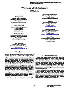
Figure 1: A Multi-homed Wireless Mesh Network.
3
Environment
A wireless mesh network is comprised of multiple access points, possibly distributed in several islands of wireless connectivity such as different buildings located close to each other or parts of the same building. Access points inside a wireless island can communicate with each other, potentially using multiple intermediate hops. We call each access point a node in the wireless mesh network. For Internet connectivity, one or more access points in each wireless island can directly connect to the wired network. Other access points rely on multi-hop communication to reach an Internet connected node in their island. The mesh clients are regular 802.11 devices that communicate with the mesh nodes to get access to the network. We do not assume any specific drivers, hardware, or software present on the clients. Therefore, any regular unmodified mobile device should be able to use the mesh network transparently. Figure 1 depicts a general overview of a the wireless mesh network paradigm. While the mesh nodes are usually stationary, mobile devices that connect to the mesh network can roam throughout the coverage area. This is one of the main differentiating factors between the mesh network and the Mobile Ad-hoc Network (MANET) paradigm, where everyone (mesh nodes and mesh clients) can move and participate in the overall routing protocol. Even though the mesh nodes are stationary, the mesh topology changes when wireless connectivity between the mesh access points changes, when nodes crash or recover, or when additional nodes are added to expand the wireless coverage.
4
The SMesh Architecture
Our goal is to allow mobile clients to freely roam within the area covered by the wireless mesh nodes, with no interruption in their Internet connectivity. All connections (reliable or best effort) opened at mobile clients should not be affected as the clients move throughout the coverage area served by
6
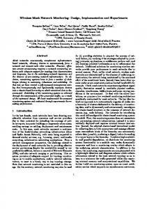
the wireless mesh. Following the above goals, we implemented SMesh[42], a wireless mesh network system that provides seamless connectivity to mobile clients. The software architecture of SMesh is shown in Figure 2. Below we describe the two main components of the SMesh architecture: the communication infrastructure and the interface with mobile clients.
4.1
Communication Infrastructure
The mesh nodes create a relatively stable ad-hoc wireless network. Within this network, the nodes need to forward packets over multiple hops in order to communicate with each other for reaching the Internet gateways or for coordinating decisions about serving mobile clients. The nodes also need to discover and monitor their neighbors and to automatically adjust the mesh routing in case of topology changes. The communication infrastructure of SMesh relies on the Spines messaging system [43, 4]. The Spines overlay network interconnects all nodes through direct links in the wireless network and through virtual links in the wired network. SMesh instantiates a Spines daemon on each wireless mesh node to forward messages within the wireless mesh. Each daemon keeps track of its own direct neighbors by sending out periodic hello messages. Based on the available connectivity, each node creates logical wireless links with its direct neighbors and uses a link-state protocol to exchange routing information with other nodes in the network. The nodes flood link-state information using reliable links between direct neighbors. This allows the nodes to send only incremental updates, and only when network topology changes. Link state updates contain only information about the wireless links that change their status. When there are no changes in topology, no routing information is exchanged. Considering that mesh nodes (access points) are mostly stationary and that topology changes are relatively rare, the incremental linkstate mechanism incurs very low overhead. Note that in SMesh, mobile clients are not part of the mesh topology. While this link-state protocol may not be optimal for a mobile ad-hoc network, it is suitable for the relatively stable network underlying our mesh of access points. Running as a software router in user-space, Spines allows us to use multicast and anycast functionality in a multi-hop wireless environment without infrastructure support. A multicast group is defined as a class D IP multicast address while an anycast group is a class E IP address. Note that the groups are defined in the Spines virtual addressing space, not in the actual IP address space of the network. When a mesh node joins or leaves a group, the local Spines daemon informs all the other nodes in the network through a reliable flood similar to the link-state protocol. Only joins and leaves are flooded to the mesh nodes in the system. The group membership is maintained in Spines in tuples of the form (mesh node address, group address), such that each node knows all the groups that other nodes are members of. Based on the group membership and available connectivity, Spines automatically builds multicast trees throughout the mesh network. A multicast data message follows the multicast tree corresponding to its group. Therefore, if several nodes in a certain vicinity join a multicast group, multicast messages exchanged between them will only be sent in that vicinity. An anycast data message follows a single path in the tree to the closest member of the group. Multicast trees in Spines are built by optimizing on a metric that can be based on number of hops, link latency or loss rate. In our tests, Spines could handle several hundred thousand group members on regular desktop machines and was limited only by the available memory to maintain the data structures. As we will show later, SMesh instantiates two groups for each client, with a few members in each group. The more limited Linksys WRT54G routers used in our experiments have enough memory to support at least 1000 mobile clients at the same time.
7
Unmodified Mobile Client Device
Communication Infrastructure
Interface with Mobile Clients
DHCP Client
ARP
Applications
Interceptor
DHCP Server
Intra-domain Handoff Algorithm
Raw Socket
Inter-domain Handoff Algorithm
Packet Proxy
Client Link Quality Control Group
Destination Data Group
Client Data Group
Internet Gateway Control Group
NAT
Overlay Router
Link-State Routing
Group Multicast
Mesh Network (UDP/IP Unicast)
Internet
Figure 2: The SMesh Architecture. 4.1.1
Topology formation
The topology formation of the mesh network starts with each access point broadcasting its presence periodically. Neighboring nodes create bidirectional links and advertise their connectivity through a link state protocol to other nodes in the network. Internet gateways join a multicast group called Internet Gateway Multicast Group (IGMG) on which they periodically advertise their wired interface IP address. This multicast group is also handled by the underlying overlay infrastructure. When two Internet gateways receive each other’s advertisements (which initially travels through the wireless infrastructure to the members of the multicast group), they connect through a wired overlay link. This way, the Internet gateways inside an island form a fully connected graph using their wired infrastructure, while the other access points inside the island interconnect based on the wireless connectivity. In order to interconnect wireless islands, at least one Internet gateway in each island needs to be pre-configured to connect to a set of Internet gateways such that an initial connected graph is formed. Then, multicast advertisements from all gateways will be propagated, Internet gateways will connect to each other, and eventually, a fully connected logical graph between all Internet gateways in all islands is formed. 4.1.2
Routing metric
In a mesh network with multiple Internet gateways, wired connections can be used to shortcut several hops of wireless communication, thus decreasing the number of wireless transmissions. For this reason our system maintains a hybrid overlay infrastructure, with both wired and wireless links. In general, in a combined wired-wireless routing metric scheme, it is reasonable to assume that a wired connection costs much less than a wireless link. On the other hand, depending on the network conditions it is possible that wired connections between Internet gateways have different costs (based
8
Type
Address
Example
Details
Client IP Netmask Default Gateway Network Address Broadcast Address Reachable IP
10.A.B.C 255.255.255.248 10.A.B.C + 1 10.A.B.C - 1 10.A.B.C + 6 10.A.B.C + 2
10.11.12.25 255.255.255.248 10.11.12.26 10.11.12.24 10.11.12.31 10.11.12.27
Assigned by SMesh DHCP Server Assigned by SMesh DHCP server Assigned by SMesh DHCP Server Calculated by Client with Netmask Calculated by Client with Netmask Used by SMesh to monitor the client
Table 1: SMesh IP addressing scheme. on throughput, loss rate, latency, etc.). Our approach uses the best route to a destination considering wireless connectivity as well as any hybrid route available, and allows for different routing metrics to be used both on the wired and wireless links. Considering that each wireless link can have an ActualCost metric of at least 1, the routing cost of that link will be: Cost = ActualCost ∗ (M + 1) where M is the maximum cost that can be associated with a wired path. For example, if a wired link can have a maximum cost of 10, and there are 5 access points connected to the Internet in the mesh network, the value of M is 40 (the largest number of wired hops in a path is 4), and the minimum cost of a wireless link is 41. The cost of a hybrid path is the sum of the cost of all the links. This mechanism gives preference to any wired link over a wireless one, and optimizes the wired path based on a desired metric. For example, we can use ETX [19] as the wireless ActualCost metric, and latency as the wired links metric.
4.2
Interface with Mobile Clients
SMesh provides the illusion of a single distributed access point to mobile clients. This is achieved by providing connectivity information to clients through DHCP [25] and by always giving the same information (IP address, Netmask, and Default Gateway) to the mobile client. 4.2.1
Mobile client connectivity
Each mesh node runs a DHCP Server that is in charge of providing network bootstrap information, including a unique IP address, to a requesting client. We compute this IP address using a hash function on the client’s MAC address, mapped to a class A private address of the form 10.A.B.C. A small portion of the private IP addresses in this range is reserved for SMesh nodes, and the rest are available to mobile clients. In case of a hash collision, the client with the smallest MAC keeps the current IP and any other client in the collision gets a managed IP. This scheme decreases the amount of IP management in the network, while assuring that each client gets the same IP address from any SMesh node. Of particular importance in the DHCP protocol are the Server ID, Default Gateway, and the T1 , T2 and Lease timers. The Default Gateway specifies the next hop router to use at the MAC level when sending to an IP address outside the client’s netmask. The Server ID specifies the DHCP Server IP address that the client should contact to renew its lease. The T1 and T2 timers specify when to start unicasting or broadcasting DHCP requests (DHCPREQUEST), and the Lease timer specifies when the client must release the IP address. After the Lease timer expires, all the connections at the client are terminated. If the access point responds to a DHCP request before the client’s Lease time expires, it is able to keep all connections open. In SMesh, the lease time is set to 90 seconds, which gives a client enough time to reconnect in case it goes out of range of any of the mesh nodes temporarily.
9
Table 1 shows our addressing scheme. We assign a small subnet to each client. Every client resides in a different subnet, thus forcing the client to send packets destined to the Internet or to a peer through its default gateway. The default gateway is set to a virtual IP address; there is no node in SMesh with that IP address. Instead, SMesh makes the client “believe” that this address is reachable by associating this IP address to a mesh node hardware address. This forces the client to route packets through a SMesh access point. While each client in SMesh consumes 3 bits from the address space, there are still 21 bits available, which allows us to support over one million client IP addresses. Section 5 explains how the virtual default gateway is mapped to a real access point, how we use the DHCP timers, and how an additional IP address in the client subnet is used to monitor its connection. 4.2.2
Packet proxy
Mesh nodes serve as default gateways for the mobile clients. A Packet Proxy module, depicted in Figure 2, uses an interceptor to grab packets from a client, and a raw socket interface to forward packets back to the client. Each mobile client is associated with a unique multicast group in the mesh, Client Data Group, for access points to receive client data. One or more mesh nodes that are in the vicinity of a client will join that client’s Data Group. If the destination of a packet is a SMesh client, the packet is sent to the SMesh nodes that joined that client’s Data Group. The mesh node sending this packet can be the Internet Gateway (for packets coming from the Internet) or a sending client access point (for packets originated by a different SMesh client). Upon receiving a packet for the client, each of the SMesh nodes that joined that client’s Data Group forwards the packet to the client. If the destination of a packet is the Internet, then the packet is sent by the originating client’s access point to the closest Internet gateway by forwarding it to an anycast group that all Internet gateways join. Since clients reside in a private address space, Internet gateways perform a Network Address Translation (NAT) [26] before forwarding the packet to the Internet. When a response packet is received from the Internet, a reverse NAT is performed and the packet is sent to the appropriate Client Data Group. Under normal circumstances, only one mesh node join this group. Spines forwards the packets to the members of the client’s Data Group using a multicast tree. This way, if the mobile client moved, and a different SMesh node joins the client’s Data Group, the packets are forwarded to the newly joined SMesh node. The SMesh node(s) in the Client Data Group use a raw socket to deliver the packet, allowing the mobile client to receive the packets unmodified as if it had a direct connection to the end host. If there are multiple nodes in the Client Data Group, the client could receive duplicate IP packets. However, duplicate IP packets are dropped gracefully at the receiver (TCP duplicates are dropped at the transport level, and applications using UDP are supposed to handle duplicates).
5
Fast Intra-domain Handoff Protocol
Real-time applications such as VoIP require that packets arrive in a steady stream. Any burst of loss where consecutive packets are lost results in degradation of quality. In addition, in the case of VoIP, packets should arrive within 100 ms to prevent a noticeable delay that impairs interactivity, and delay variability should stay below 20 ms to ensure the highest quality of service. Therefore, a handoff protocol should be fast enough to avoid any packet loss, and should ensure that packets are delivered to their destination in a timely manner. When 802.11 devices are configured in infrastructure mode (BSS), they inherently perform their own scanning for a better access point. A layer 2 handoff takes place through a re-association request/response process which can last as long as several seconds [48]. In addition, this handoff 10
is both hard and forward; hard because the client can only speak with one access point at a time, and forward because the client can not communicate with its old access point during the handoff process. A typical handoff will last about 500 ms, which translates to dozens of lost packets per handoff for VoIP applications. In order to avoid this behavior and control the handoff solely from the access points, we configure both the access points and the mobile clients in ad-hoc mode (IBSS). This is one of the standard modes of operation available on any 802.11 compliant device. One way to perform the handoff in ad-hoc mode is by relying on the DHCP protocol. For example, one can instruct the client to renew its lease every few seconds. Any access point that hears the DHCP request may respond and become the default gateway for the client. While this mechanism may provide some handoff capability, handoff can still take seconds as nodes need to wait for the client to initiate the DHCP transaction. Moreover, the client may connect through an access point that has a weak connection, while better nodes may be available. Instead of letting the client “decide” when the handoff should take place, we make the SMesh nodes track their connectivity to the client and force the client to change its access point when better connectivity is available (avoiding oscillations is described below). To achieve this without modifying anything on the client side, we provide the illusion of a single IP that never changes as the default gateway of the client and use gratuitous ARP messages to force roaming to the SMesh node with the best client connectivity. The details of our intra-domain handoff protocol are described below. These include measuring and sharing the link quality metric to determine the best access point for each client, the use of overlay multicast groups for managing the clients, and the actual handoff process.
5.1 5.1.1
Mobile Client Monitoring Seamless heartbeat with DHCP and ARP
In order to provide continuous connectivity and availability to the mobile client, we need to continuously monitor the client. To achieve seamless monitoring without any involvement from the client, we developed two strategies. 1. DHCP (Dynamic Host Configuration Protocol) According to the DHCP standard [25], the T1 (Renew) and T2 (Rebind) timers specify when to start unicasting and broadcasting, respectively, DHCP requests (DHCPREQUEST), and the Lease timer specifies when the client must release the IP address. After the Lease timer expires, all the connections at the client are terminated. If the access point responds to a DHCP request before the client’s Lease time expires, it is able to keep all connections open. When using the SMesh DHCP monitor, our DHCP server instructs the clients to renew their IP address every 2 seconds, thus serving as a heartbeat to keep track of the client. In addition, the timers may be set so that the client unicast or broadcast their request every 2 seconds. On the down side, it employs a non-negligible overhead as a DHCPREQUEST packet is at least 300 bytes long, and a DHCPACK is about 548 bytes. Another downside is that, when the first DHCPREQUEST is lost, the time between this request and the next is platform dependent and usually more than several seconds. This is the approach we took in [6]. 2. ARP (Address Resolution Protocol) ARP [36] protocol is used to map an IP address to a hardware address (MAC), when a host (or router) wants to communicate with another host inside the same network. In general, given an IP address for which its corresponding hardware address is not present in the ARP cache of a client, the ARP module of that client will broadcast an ARP request packet. In addition to the source and destination IP addresses, this ARP request contains the MAC address of the source. The value of the destination MAC is not yet known. All the hosts on the local network 11
receive the packet and compare the destination IP with their own IP address. The host for which the IP address matches will issue an ARP reply, filling in the destination MAC field with its own MAC address. This packet is sent directly via unicast to the requesting client. However, even if the hardware address is known, we can still use this protocol to probe the client’s link and estimate its loss rate. By using regular ARP requests, we can make the client either unicast or broadcast ARP responses. We instruct the client to send its reply to a special IP inside its subnet, with the MAC address of the access point that sent the reply (e.g., a heartbeat sent by access point 10.0.0.31 to client 10.11.12.25 is ARP packet “Who has 10.11.12.25? Tell 10.11.12.27.”, where the MAC address associated with 10.11.12.27 is set to be the real MAC of 10.0.0.31). This is necessary as the real IP address of the SMesh nodes is outside the client network. The advantage of using this approach is that, unlike DHCP, ARP packets are very small, only 28 bytes. In SMesh, we request an ARP reply from the client every one or two seconds. Also, to limit the number of access points probing the client, only the mesh node in the client Data Group periodically sends a request, and all nodes in the vicinity use the reply to compute the metric. This is the approach that we take in our current version of SMesh and for the experiments presented in this paper. It is also possible to use regular packets sent by the client to monitor its connectivity1 . However the approaches presented above are still necessary when the client is idle and there is no incoming/outgoing traffic. 5.1.2
Quality metric
We use the monitoring schemes described above to keep track of the quality of the links to mobile clients. Both schemes allow us to receive either unicast or broadcast replies from the client. Using broadcast instead of unicast eliminates the link-level retransmissions of the requests, which allows us to estimate more accurate the loss rate. Each SMesh node computes a client link quality metric based on the observed loss of a client’s DHCP requests or ARP responses, using the following weighted average decay function: Mnew = Mold ∗ Df + Current ∗ (1 − Df ) , 0 < Df < 1 where M is the link quality measure and Df is the decay factor. Current is a constant value which is set to 0 if the access point did not receive any DHCP or ARP probe packets responses in the expected time, or is set to a maximum value if a probe packet is received. The access point calculates this function every second for each client in its vicinity. SMesh uses a decay factor of 0.8 to make the protocol resilient to occasional wireless losses of the probe packets, while maintaining its adaptability to network condition changes. SMesh uses a Current value of 50 to allow integer calculations with discrete mapping. The tie breaker between two access points having the same integer metric (in the range of 0 to 50) is according to the lowest IP of the access point. Many wireless devices allow applications to capture packets through a monitoring interface. When the mesh node is also equipped with such an interface (as in the case of our Linksys routers), specific radio measurements from the received packet, as well as the complete 802.11 frame, is available to SMesh, as follows: 1. RSSI (Received Signal Strength Indicator) RSSI is a measurement of the radio signal strength. If the wireless interface is configured in monitor mode, an additional header is added by the wireless driver, which contains the RSSI information. One thing we must be aware of is that the RSSI value must be in the same range 1 When a client is receiving data, it needs to send an acknowledgment at the 802.11 level for every packet it receives, which can also be used to monitor connectivity.
12
of values for all mesh nodes. If different card manufacturers are used, a conversion might need to be performed (e.g., Cisco Systems cards report a maximum RSSI value of 100, while Atheros cards report a maximum of 60). 2. 802.11 Retransmission Flag Every unicast packet transmitted in 802.11 needs to be acknowledge by the recipient. If the packet or the acknowledgment is lost, the sender retransmits the packet, and sets a retransmit flag in the 802.11 header. The maximum number of retransmissions is usually four. In our case, instead of using a broadcast heartbeat to know when packets are lost on the first transmission, we look at this flag to determine if the packet was lost on the first attempt. The main advantage of using RSSI versus a loss-rate only measurement is that we can start the handoff process to a better access point before there is any loss in the medium. The initial loss in the medium is usually masked by the 802.11 retransmissions, so the client sees this loss as an increase in latency for these packets. However, RSSI alone is not a good indication of the loss rate of a link, so we use it in conjunction with the loss rate, adjusted with the decay function described above, for measuring the quality of the link.
5.2 5.2.1
Intra-domain Mobility Management Mobile Client Data Group
A mesh node joins the client Data Group so that it can receive and forward data packets for that client, if it believes it has the best connectivity to the client based on link quality metrics it receives from other nodes. Nodes in a Client Data Group receive data packets that need to be forwarded to the corresponding mobile client. If more than one node is a member of this group, duplicate packets will be sent to the client by each member of the group. Our protocol must guarantee that, at all times, there is at least one member in the Data Group of each client, such that the client will be served by at least one mesh node. On the other hand, it would be wasteful to allow more than one node in the vicinity of a client to also be in the Data Group most of the time as this creates duplicate packets. Our protocol balances between these two conflicting goals (availability and efficiency). 5.2.2
Mobile Client Control Group
In addition to the previously described Client Data Group, used to forward data packets in SMesh towards the access points serving the client, the access points in the vicinity of a client join a different multicast group specific to that client, called Client Control Group. The Client Control Group is used to coordinate with other mesh nodes in the client’s vicinity regarding link quality metrics and regarding which access point will be the best to serve that client. A mesh node joins a client’s Control Group when it receives one heartbeat from the client, and leaves the group after not hearing from the client for some time. Both Control and Data group names are derived from client’s IP address. For example, for a mobile client with address 10.A.B.C, a SMesh node will join the client’s Control Group at 224.A.B.C and, if needed, the client’s Data Group at 225.A.B.C. This maps every client to a set of two unique multicast groups2. The link quality metric is shared by the access points periodically by posting it on the client’s Control Group. Since only the nodes receiving a heartbeat from a client join the client’s Control Group, the multicast overhead is localized only in the vicinity of that client and will not propagate beyond that in the network. 2 Control
Groups and Data Groups are implemented as Spines multicast groups.
13
5.3
Client Handoff
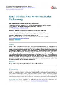
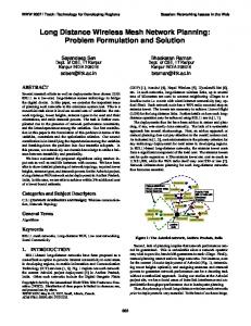
Each mesh node has its own IP address that allows it to communicate with other mesh nodes. However, in order to provide a completely transparent handoff to clients, mesh nodes advertise a virtual gateway IP address to all clients in their DHCP offers and acknowledgments (DHCPOFFER and DHCPACK). Mobile clients set their default gateway to this virtual IP address regardless of which access point they are connected to. This way, mobile clients get the illusion of being connected to a single access point that follows them as they move. The IP address of the default gateway only appears in the DHCP offer. In all other IP communication with mobile clients, the default gateway does not even appear in the IP packets. It can be set to any valid IP address in the client subnet as the communication with the mobile clients is solely based on MAC addresses. Our handoff mechanism uses gratuitous ARP messages to instantaneously change the access point used by the mobile client. A gratuitous ARP is an ARP reply packet that is not sent as a reply to an ARP request, but is rather sent in the local network voluntarily. Upon receiving such a packet, a host will update its ARP cache with the value it received. Typically, gratuitous ARPs are used by hosts to advertise their new hardware address when their network card is changed. When a SMesh node believes it has the best connectivity with the client and decides to serve that client, it sends a gratuitous ARP as a unicast, directly to the client, thereby changing the MAC address of its default gateway. Subsequent packets sent by the client will be sent to the new access point, following the new hardware address. All operating systems that we have tested accept gratuitous ARPs and begin using the new MAC-IP mapping immediately. In addition to sending a gratuitous ARP to the mobile client, when a node believes it has the best link quality to a mobile client, it joins its Data Group so that packets destined to the client start flowing through this access point. If another node is also a member of the Data Group, packets destined to this client are forwarded to both mesh nodes, and each of them forwards the packets directly to the mobile client. The mobile client may receive duplicate packets at this time. Using multicast helps achieve uninterrupted connectivity during handoff by: (1) sending packets through multiple access points to the mobile client, to deal with unexpected client movements while the best access point for the client is chosen, and (2) avoiding loss while route changes take place in the wireless mesh. A mesh node that joins the Data Group of a mobile client immediately sends a metric update on the Control Group to inform any other node of its latest metric, noting that it is now a member of the client’s Data Group. When a mesh node that is a member of the Data Group receives a link quality metric update that shows that a different node in the Data Group is better connected, it issues a Leave Request. Leave Requests, sent on the Control Group, are piggy-backed on link quality metric updates. A Leave Request can be acknowledged only by a node in the Data Group that believes that it has the best connectivity to the client. A node may leave the Data Group if and only if its request is acknowledged by at least one other node. The state machine for handling mobile clients is depicted in Figure 3, and the pseudocode depicting our algorithm is shown in Figure 4. Note that a node checks periodically (line A4) if it should service the client, instead of checking immediately after receiving a metric update, to be less aggressive in taking a decision. However, nodes that are already servicing the client check their state immediately after receiving an updated metric (line F2) to service the handoff as fast as possible. During disagreements, more than one node may be a member of the Data Group for some time, until the disagreement is resolved. When a node issues a Leave Request, it includes a unique id that increases each time the mesh node enters the RequestingToLeave state (line B11). A node can acknowledge a Leave Request only if it is currently the one handling the client (line D2). Note that a node cannot leave unless it receives an acknowledgment with the ID used in the last Leave Request (line E2). This mechanism guarantees that at least one node is a member of the Data Group at all times, unless this node crashes. Our experiments show that this usually lasts less than a quarter of a second during handoffs.
14
Client out of reach Timeout
Evaluate_Local_State AND NOT Handle_Client
New Client Detected
Monitoring Client
Idle
Metric_Update AND Handle_Client2
Evaluate_Local_State AND Handle_Client
Handling Client
Client out of reach Timeout Metric_Update AND Handle_Client2
Receive Leave Request ACK AND Valid Leave Request ID Acknowledged
Metric_Update AND NOT Handle_Client2
Requesting to Leave
( Metric_Update AND NOT Handle_Client2 ) OR Leave Request Loss Timeout
Conditions Handle_Client:
My_Metric > Highest_Metric(Data Group) * Threshold AND My_Rank(Nodes in MonitoringClient state) (Highest Metric(DGi Members) * Threshold) and My Rank