The Split-Phase Synchronisation Technique: Reducing the Pessimism in the WCET Analysis of Parallelised Hard Real-Time Programs Mike Gerdes, Florian Kluge and Theo Ungerer
Christine Rochange
University of Augsburg, Germany Email: {gerdes,kluge,ungerer}@informatik.uni-augsburg.de
University of Toulouse, France Email:
[email protected]
Abstract—In this paper we present the split-phase synchronisation technique to reduce the pessimism in the WCET analysis of parallelised hard real-time (HRT) programs on embedded multicore processors. We implemented the split-phase synchronisation technique in the memory controller of the HRT capable MERASA multi-core processor. The split-phase synchronisation technique allows reordering memory requests and splitting of atomic RMW operations, while preserving atomicity, consistency and timing predictability. We determine the improvement of worst-case guarantees, that is the estimated upper bounds, for two parallelised HRT programs. We achieve a WCET improvement of up to 1.26 with the split-phase synchronisation technique, and an overall WCET improvement of up to 2.9 for parallel HRT programs with different software synchronisations.
I. I NTRODUCTION Research in parallel programs and architectures was bound to the domain of high-performance computing for a long time. With the upcoming of multi-core processors, parallelisation became also important in other domains, namely desktop enduser systems and embedded systems. However, embedded systems have different needs and must fulfil other requirements than high-performance systems. Today’s HRT programs in the automotive, avionic or machinery industry are executed on single-core processors. The new trend of using multicores in safety-critical domains sparks off research on running HRT tasks in parallel with other tasks to execute mixedcritical application workloads. Our research goes even one step further: we target multi-core execution of parallelised HRT tasks without sacrificing timing guarantees. The threads of a parallelised program require synchronised access to shared data. Hence, it is essential for parallelised HRT programs to assert predictable access to shared resources as well as upper bounds to waiting times introduced by the execution of synchronisation primitives. Although it has been shown that parallelised HRT programs are timing analysable with static worst-case execution time (WCET) analysis tools [1] [2], it is an open problem to reduce the pessimism in the static WCET analysis introduced from interfering accesses to shared resources. This pessimism becomes apparent, for instance, in the worst-case latencies of memory requests in shared-memory multi-core processors. The contribution of this paper is to introduce the split-phase synchronisation technique to reduce this additional pessimism
in the static WCET analysis of parallel HRT programs. Our technique aims at making the frequent case faster, that is it reduces the WCET of frequent (and fast) load/store accesses, while sacrificing worst-case performance of more seldom (and slower) synchronisation accesses. The split-phase synchronisation technique has been implemented in hardware allowing the reordering of memory accesses in the memory controller. We show that our proposal preserves consistency through weak ordering in hardware, and predictability by using HRT capable software synchronisation techniques as introduced in [1]. We discuss and motivate why we implement the synchronisation logic and split-phase synchronisation in an augmented memory controller, instead of locking the interconnect or implementing a dedicated shared memory for synchronisations at the interconnect. We evaluate the improvement of the worst-case guarantees and compare the WCET estimates from the static WCET analysis tool OTAWA [3] of different parallelised HRT programs with and without the split-phase synchronisation technique. In Section II we depict related work. In Section III we shortly present the modelled HRT capable MERASA multicore processor [4], introduce worst-case memory latencies (WCMLs), and discuss consistency and atomicity requirements on the hardware for synchronisations in HRT parallel programs. The split-phase synchronisation technique is then presented in Section IV, and evaluation results with the static WCET tool OTAWA are shown in Section V. II. R ELATED W ORK Monchiero et al. [5] present an augmented global memory controller, the Synchronisation-operation Buffer (SB), to reduce contention for busy-waiting synchronisation primitives in future mobile systems with complex Networks-on-Chip (NoCs). Their main focus is on reducing contention, and therefore enabling an efficient use of busy-waiting synchronisations like spin locks. The goal of their technique is to decrease the average-case execution time by speeding up slow synchronisation primitives, while also enabling a fine-grained synchronisation. Another approach, the Request-Store-Forward (RSF) model, has been proposed by Liu and Gaudiot [6] targeting many-core architectures in high-performance computing. The goal of the RSF technique is to provide a fine-grained synchro-
nisation technique and to reduce contentions of busy-waiting and polling synchronisation methods. A synchronisation buffer implemented in on-chip memory (e.g. a shared cache), keeps track of synchronisations (requests), orders them (store), and notifies (forward) the cores when the synchronisation access is ready. By offloading this computation near the memory, they could use the waiting times in the cores to execute other tasks until they are notified that their synchronisation access is ready. Contrarily to the above solutions, we focus on speeding up the worst-case performance of the frequent case of memory operations, like loads and stores, with our augmented memory controller and the split-phase synchronisation technique. In this paper we do not go into detail about the physical implementation of DRAM accesses. The memory latencies used in this paper have been derived from an FPGA prototype of the MERASA architecture [4]. However, the authors of [7], [8], and [9] provide different solutions concerning predictable DRAM access and their detailed physical implementation. Only very few publications have been targeting WCET analysis of parallel HRT programs so far. Gustavsson et al. [10] present the chain of a possible static WCET analysis of multi-core architectures. They use timed automata to model the various components of a multi-core architecture, including private and shared caches, but also software-level shared resources like spin locks. The WCET of the parallel program is then derived by model checking. To estimate the WCMLs a predictable arbitration scheme for shared resources, that is the off-chip memory, is mandatory. In the MERASA processor, which we use as WCET model in this paper, this is done by a predictable round-robin arbitration in the bus [11]. In a recent publication [12], the authors refined the round-robin arbitration proposing a harmonic round-robin arbitration. In that way, memory intensive programs are given access to the bus more frequently by prioritising them in the bus scheduling. Further approaches for predictable bus arbitration using a TDMA scheme are presented in [13], and [14]. In [15] the authors state a different method for estimating upper bounds for memory latencies by linking task- and system-level analyses. In [16], we introduce basic principles of analysing the worst-case waiting times in synchronisation functions. The idea is to determine all the paths on which a thread holds any systemlevel or application-level synchronisation variable, and their estimated WCETs are combined to compute the worst-case waiting times at synchronisation points. In [2] we present first results on the static WCET analysis of an industrial, parallel HRT application. We considered a limited set of synchronisation functions based on test-and-set (TAS). In [1] we then further investigated predictable HRT capable implementation of common software and hardware synchronisation techniques, and their impact on the program’s WCET. We used TAS, and Fetch&Increment/Fetch&Decrement (F&I/F&D) as hardware primitives, and mutex locks, semaphores, and barriers as software synchronisation techniques. In the current paper, we consider those above proposed synchronisation techniques in parallelised HRT programs and combine them with the splitphase synchronisation technique in a static WCET analysis.
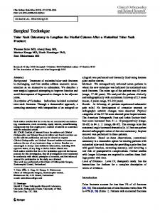
Core 1
Core 2
Core 3
Core 4
D-SPM I-SPM
D-SPM I-SPM
D-SPM I-SPM
D-SPM I-SPM DSP D-ISP
Real-time bus arbitration
Memory controller with synchronisation logic
Shared memory Fig. 1. Overview of the MERASA multi-core processor, stressing the embedded hardware synchronisation primitives in the memory controller.
III. P REDICTABILITY IN M ULTI - CORE P ROCESSORS We use a WCET model of the bus-based, HRT capable SMT-multi-core MERASA processor [4], which has also been implemented as a SystemC simulator and FPGA prototype. The modelled MERASA processor features a configurable number of HRT capable cores and hardware thread slots. One hardware thread slot of each core is reserved for a HRT thread, and the other hardware thread slots are used by non-hard real-time (NHRT) threads. The HRT threads are isolated in the cores [17], but the memory controller and interconnect cannot isolate concurrent accesses of different cores. Besides, a partitioning of global memory would impede the use of a global address space, and hence narrow down the programmability for users. Therefore, we have chosen to allow shared resources. Interferences are handled by an upper bounding of accesses to shared resources like a real-time capable bus [11] as interconnect to memory and cores, as well as a real-time capable memory controller. As local memories we use scratchpad memories for each core, namely a data scratchpad (D-SPM) and a dynamic instruction scratchpad (ISPM) [18], but no caches for the HRT threads. However, we allow caches to be used by NHRT threads. Fig. 1 depicts an overview of the MERASA multi-core processor. A. Worst-case Memory Latencies The WCETs of parallelised HRT programs running on shared-memory multi-core processors are depending highly on the knowledge of competing off-chip memory accesses and the WCMLs. The latency for a memory request is split into three parts: 1) the time the bus needs to dispatch the memory request from a core to the memory controller, the so-called bus cycle time; 2) the time the memory controller needs to execute the memory request, which is depending on which kind of memory request is executed, either a load, a store, a TAS, or a F&I/F&D operation; and 3) again the bus cycle time to return a value to the core that requested the memory operation. The memory requests from all cores to the global shared memory are arbitrated by a real-time aware bus in the MERASA processor. The bus arbitrates accesses in a roundrobin fashion, dispatching a waiting memory request of a core to the memory controller. When a memory request from a
core is accepted and dispatched to the bus and subsequently to the memory controller, follow-up memory requests from the same core are dispatched after the previous access has been finished. In the following, the WCMLs are defined as the upper bound delay on a HRT memory request from when it is ready to be dispatched to the shared memory (over the bus) until it is successfully finished and a following request could be dispatched. The bus is treated as full duplex, meaning that a request from a core to the memory and a result from the memory to a core can be dispatched at the same time. B. Consistency and Atomicity Sequential consistency, introduced by Lamport in [19], has two requirements: (R1) Each processor issues memory requests in the order specified by its program, and (R2) memory requests from all processors issued to an individual memory module are serviced from a single FIFO queue. The HRT capable MERASA multi-core processor fulfils those two requirements through the arbitration in the cores (R1) and the augmented memory controller (R2) (see [4]). In later publications, the notion of weak ordering [20] has been introduced (see [21] for a further definition of weak ordering). The idea of weakly ordered systems is that they appear sequentially consistent by ordering accesses dispatched from different processors with explicit synchronisation operations that can be recognised by hardware. In detail, bringing the requirements for weakly ordered memory operations stated in [20] together with the MERASA multi-core processor: 1) accesses to global synchronisation variables are strongly ordered, 2) no access to a synchronisation variable is issued in a core before all previous global data accesses have been performed and 3) no access to global data is issued by a core before a previous access to a synchronisation variable has been performed. In Section IV-B we show that these requirements still hold with the split-phase synchronisation technique. The use of synchronisation techniques (see [22] for a survey on software synchronisations, and [23], [1] for implementations of predictable synchronisation techniques), for instance to avoid data races, is mandatory for functional correctness of parallel programs. One possibility to use software synchronisation techniques in parallel HRT programs is with the support of hardware-implemented RMW operations. A mandatory requirement for the implementation of RMW operations is atomicity. It ensures that an operation consisting of a read, a modification and a write cannot be interrupted, and will be executed completely. For a bus-based, shared-memory multicore two different possibilities to implement atomicity for RMW operations are conceivable: 1) locking the interconnect and modify in cores, or 2) logic for atomic operations in the memory. The latter one could be either implemented in the memory controller of the shared global memory or as a dedicated shared memory for synchronisations at the interconnect (e.g. like shared L2 caches in high-performance systems). In the following we discuss why we augmented the memory controller with the needed logic for the atomicity of RMW operations and the split-phase synchronisation technique.
Core 1 (RMW) B M1 M2 M3 ... Mn B Core 2 (Load) X B
X X X
...
C
B M1 M2 M3 ... Mm B
X X X X X X X
...
X
B M1 M2 M3 ... Mn B
(a) Locked interconnect Core 1 (RMW) B M1 M2 M3 ... Mn C M1 M2 M3 ... Mm B Core 2 (Load) X B
X X
B
...
X X X X X
...
X
M1 M2 M3 ... Mn B
(b) Augmented memory controller Core 1 (RMW) B M1 M2 M3 ... Mn C Core 2 (Load) X B
B
X X
...
X
X X
... ... X M1 M2 M3 ... Mm B
M1 M2 M3 ... Mn B
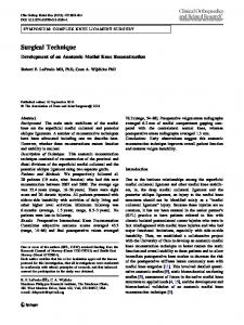
(c) With split-phase synchronisation technique Fig. 2. Memory access pattern for implementing RMW operations with a locked interconnect (a), with the augmented memory controller (b), and with the split-phase synchronisation technique (c).
1) Locking the Interconnect: Fig. 2 depicts the impact of a RMW operation (from core 1) on the memory latency of a load (from core 2) with a locked interconnect (see Fig. 2(a)), with the augmented memory controller (see Fig. 2(b)), and with the split-phase synchronisation technique (see Fig. 2(c)). The blocks with a ’B’ depict bus accesses, M1 , ..., Mn depict memory accesses, ’C’ is the computation for the modification in RMW operations, and the blocks with ’X’ depict idle cycles, e.g. when the bus is locked, or the memory controller is busy with an other memory access. When locking the interconnect for RMW operations, the WCML of every memory access increases. For instance, Fig. 2(a) shows for two cores that the WCML of a load in core 2 is at least 3 cycles higher (the additional bus cycles are labelled in Fig. 2(a)) than with an unlocked interconnect and the synchronisation logic embedded in the memory controller (see Fig. 2(b)). These additional latency cycles are adding up when scaling the number of cores. Also note that the time the computation phase takes to manipulate the value in a RMW operation is depending on where this computation is done. The computation time might be higher if the computation is done in the core, whereas one cycle is possible if the computation is done in the augmented memory controller. Also, the additional latency adds up for every memory access, thus the estimated WCET of the whole program increases. 2) Augmented Memory Controller: The augmented memory controller (see Fig. 1), described in more detail in [1], includes the needed logic for atomicity of RMW operations. It serves all memory request in the order they arrive (FIFO). Also, the memory controller recognises a synchronisation access, a RMW operation, and executes the load, the modification and the subsequent store atomically. We do not distinguish HRT and NHRT requests in the memory controller, as e.g. proposed in [7], because in our case it does not speed up the worst-case performance. For the WCML of a memory request from one core we have to assume that all other concurrent memory requests issued from the other cores are HRT requests as well, therefore prioritising them does not cause any speedup in the worst-case. In Section V-A we describe the impact on the WCMLs in more detail. Nonetheless, we isolate HRT and NHRT threads inside the SMT-cores [17], [4].
Core 1
Core 2
Core 3
Core 4
D-SPM I-SPM
D-SPM I-SPM
D-SPM I-SPM
D-SPM I-SPM DSP D-ISP
Real-time bus arbitration (including logic for synchronisations)
Synchr. memory
Memory controller
Shared memory
Fig. 3. Schematic overview of a dedicated synchronisation memory at the memory interconnect, including the synchronisation logic at the real-time bus.
3) Synchronisation Memory on the Interconnect: Fig. 3 shows an additional possibility to achieve atomicity for RMW operations by using a dedicated shared memory at the interconnect for synchronisation variables. The advantage of this approach is that faster load/store operations could be executed in parallel with slow RMW operations. The needed synchronisation logic is nearly the same as for the augmented memory controller, but additional arbitration logic in the bus is needed, as it is possible that requests from the off-chip memory and the synchronisation memory finish in the same cycle. This also leads to the problem of a possible increase in the WCMLs of loads/stores, because even if synchronisation memory requests are served with less priority, they need to be handled eventually as otherwise they cannot be bounded anymore. This would add an extra cycle to the WCML of every load/store. Another drawback are the additional costs for the on-chip memory and the loss of flexibility e.g. as the number of possible synchronisation variables is bound to the size of the synchronisation memory. Additional initialisation and memory management for synchronisation variables, however, should not to be a problem. However, it might be a promising approach, as e.g. shown in [24] for NoC-based multi-core processors. The authors of [24] present results on average synchronisation performance for a 16-core NoC-based multi-core processor. The best results were achieved with a dedicated onchip memory for synchronisation variables. They conclude that for future NoC-based multi-cores the trade-offs for area versus performance should be taken into consideration. Though, in this paper we favoured the approach of the augmented memory controller with the split-phase synchronisation technique as it promises higher flexibility, less hardware costs, and a less complex bus arbitration. IV. S PLIT- PHASE S YNCHRONISATION The split-phase synchronisation technique is a modification of the augmented memory controller to reduce the pessimism in the WCET for loads/stores introduced from slower (synchronisation) memory operations. To achieve reduced WCMLs for loads/stores, we reorder memory operations in the augmented memory controller. We prioritise load/store operations over RMW operations, while keeping sequential consistency with weak ordering as defined in [21]. In Section IV-B we
show that the split-phase synchronisation technique maintains consistency and atomicity of RMW operations. The split-phase synchronisation technique uses a similar technique as the load-linked/store-conditional (LL/SC) primitive, which is e.g. used in the Alpha AXP [25], PowerPC, ARM, and MIPS architectures. The advantage of LL/SC over e.g. compare-and-swap (CAS) is that the two separated instructions only need two registers (address, data) instead of three. Most LL/SC implementations apply a coarse-grained approach, namely they do not monitor changes on the granularity of memory words, but lines of memory or even complete memory pages. LL/SC was initially intended to scale well on large multiprocessors with distant shared memory. However, as the conditional store might fail for competing accesses, the latency for a successful conditional store cannot be bounded. Thus, their use is not safe in HRT systems. Also, LL/SC is a hardware primitive, whereas the split-phase synchronisation is a technique used on all implemented RMW operations. It splits their load, modification and store phases to reduce the worstcase memory latencies of loads/stores by prioritising them over concurrent RMW operations, and uses a fine-grained approach monitoring accessed synchronisation variables in the memory controller. Please note that the term split-phase synchronisation is not related to the commonly known splitphase access introduced by Culler et al. in Split-C [26]. In the following we present a hardware implementation of the split-phase synchronisation technique in the augmented memory controller of the MERASA processor. Discussions on the impact of the split-phase synchronisation technique on the WCMLs and the estimated WCET are presented in Section V. A. Implementation in the Augmented Memory Controller The split-phase synchronisation technique is implemented in the augmented memory controller. In detail, we split the RMW operations into three phases: A load phase, a modification phase, and a store phase. We allow other memory operations that do not access the same variable to be brought forward and executed before the store phase of the RMW operation. The target of the split-phase synchronisation is to achieve WCMLs for loads/stores that are, in a manner of speaking, the best-possible worst-case. That means that the WCMLs of loads/stores only depends on concurrent (fast) loads/stores and not on concurrent (slower) RMW operations from other cores. Memory requests are handled as described in Section III. For the split-phase synchronisation, further hardware changes in the augmented memory controller are needed to allow the reordering while preserving atomicity (see Section IV-B). The following proposed implementation does not claim to be the best possible technical solution. Further enhancements might decrease the needed logic and space, or even increase the average-case performance. It is mandatory that the logic of the added register files can be executed as fast as possible, preferable in one cycle, to reduce the impact on WCMLs. From the worst-case timing analysis perspective we think it is sufficient to prove that a working technical implementation is possible that fulfils the requirements of consistency and atomicity for
From and to cores
Real-time Bus Incoming request
Memory response
RMW modification feedback mem_buffer load a 0 2 loadRMW b 0 2 storeRMW b 1 3 loadRMW b 1 3 storeRMW b 1 4 load c 0 1
reorder_buffer 2 storeRMW b 0 3 loadRMW b 1 3 storeRMW b 1
Augmented Memory Controller
sync_buffer b 4 synchronisation logic (modification phase)
Reorder phase (after dispatch) Update Dispatch
SDRAM Fig. 4. Schematic overview of the augmented memory controller with implemented hardware for the split-phase synchronisation technique.
the split-phase synchronisation technique. Therefore, the main focus is not on the details of the technical implementation, but on the approval of predictable worst-case timing. The proposed hardware implementation in the augmented memory controller uses two register files as FIFO buffers for memory requests (see Fig. 4). One register file, the mem buffer, is used to store all memory requests, whereas the other register file, the reorder buffer, is used as a temporary buffer to reorder the load/store requests of split RMW operations and load/store accesses on synchronisation variables. Also, a buffer sync buffer is used to store synchronisation variables and a counter for each ongoing synchronisation access. Synchronisation accesses are either RMW operations, or also loads/stores on a synchronisation variable, as e.g. a store in the unlock operation of a TAS spin lock (see also Section V-B). 1) Incoming Requests: Memory requests are distinguished between load/store and RMW operations in the augmented memory controller. In Fig. 4 we use the following syntax for different memory requests: 1 load a for a load from core 1 on memory address a, 2 loadRMW b and 2 storeRMW b for the load respectively the store phase of a RMW operations on memory address b from core 2. For an incoming load/store operation the memory controller first checks if the load/store accesses a synchronisation variable that is already being accessed (and therefore would be in the sync buffer). If not, the load/store is just added to the mem buffer without setting the reorder flag. In the other case, it is added with the reorder flag set, and the counter of the accessed synchronisation variable is incremented in the sync buffer. When a RMW operation is detected, the load and store accesses are split, and if no other synchronisation request on that variable is stored in the sync buffer, the memory address of the RMW operation is added to the sync buffer with the counter set to two. In the mem buffer both accesses are stored, where only the reorder flag of the storeRMW is set, but not for the loadRMW access.
On the other hand, if there is already an access to that synchronisation variable in the sync buffer, the counter for that address will be increased by two (e.g. to four as depicted in Fig. 4 for the synchronisation variable b), and both split accesses are stored in the mem buffer with the reorder flag set. This is done as in the reordering phase we must assure that this RMW operation must not start before the store phase of the previous ongoing RMW operation on the same memory address is completed to maintain atomicity. 2) Dispatching: Each time the memory controller is ready to dispatch a new request from the mem buffer, it checks its reorder flag. If the reorder flag is not set, that memory request is dispatched. Else the next memory request without the reorder flag set will be selected from the mem buffer and dispatched, and the reordering starts. If there is no request without the flag set, the first entry is dispatched and also the reordering phase starts. Also, when a synchronisation access is dispatched, the counter of the corresponding memory address in the sync buffer is decremented. Furthermore the synchronisation logic is notified what kind of memory access is currently processed. This is needed as for case 1), the memory access will be finished and dispatched directly to the cores over the real-time bus (dotted arrow in Fig. 4), e.g. for a normal load/store. Or, in case 2), for a RMW operation that does not need the loaded value for modification, that is a TAS operation, the synchronisation logic removes the reorder flag of the corresponding store in the mem buffer. Finally, in case 3), the loaded value needs to be modified and then it is transferred to the corresponding store in the mem buffer for all other RMW operations, for instance F&I/F&D operations. 3) Reordering: In the reordering phase all accesses in the mem buffer with the reorder flag set are moved to the reorder buffer. For the first access that is moved to the reorder buffer, e.g. 2 storeRMW b in Fig. 4, the reorder flag is removed. Otherwise the waiting store of a RMW operation might be deferred infinitely by incoming concurrent load/stores of other cores that would be executed before that waiting store (see also the worst-case access pattern in Fig. 5). However, by removing the reorder flag, and with the FIFO policy of the mem buffer, we ensure that this access is dispatched before all freshly incoming requests. When all accesses in the mem buffer are processed, the accesses in the reorder buffer are appended to the mem buffer. For instance, in Fig. 4 the 4 load c access would advance the 2 storeRMW b access in the reordering phase. B. Consistency and Atomicity of RMW operations A mandatory requirement is to maintain consistency and atomicity of RMW operations, meaning that the parallel program must still execute functionally correct when using the split-phase synchronisation technique. Atomicity of split RMW operations is trivially satisfied. That means that 1) neither the accessed variable is changed by other accesses than the ongoing RMW operation, and 2) nor can the RMW operation finish incomplete (e.g. meaning that the store phase never finishes). Only load/store accesses to other variables are brought
forward and executed in between the load/modification phase and the store phase of a split RMW operation. Therefore, the accessed variable is not changed between the load/modification phase and the store phase, and requirement 1) holds. Also, through the logic in the reordering phase it is asserted that every waiting memory request is dispatched eventually, that is the waiting time for every access to be finished has an upper bound. So, 2) is also satisfied, and thus the split- phase synchronisation technique does not breach the atomicity of RMW operations. We assume that the programmer takes care of explicit synchronisation, e.g. critical sections are secured with locks and temporal dependencies are handled with barriers—both implemented with RMW operations as detailed in [1]. Also, we presume that the hardware and software implement weak consistency as described in Section III-B. However, we must assure that the split-phase synchronisation technique maintains the consistency model. The requirement 1), strongly ordered accesses to synchronisation variables, is maintained by the use of reorder flags in the augmented memory controller and atomicity of RMW operations. The other two requirements are trivially maintained by the MERASA processor, because due to in-order program execution in the cores, only one memory request from a core can be dispatched at a time to the memory controller (see Section III). In this paper, we only assume one single memory controller. However, it is possible to extend our approach to architectures with multiple memory controllers, if the needed logic for the split-phase synchronisation technique would be implemented in each memory controller. V. E VALUATION Approaches to estimate the WCET of critical tasks have received much attention in the last fifteen years [27]. Those based on static analysis techniques aim at determining guaranteed upper bounds on the real WCET, so called worstcase guarantees, taking into account the specificities of the target hardware. In this work, we use the open-source static WCET analysis tool OTAWA that implements state-of-theart algorithms for WCET analysis [3]. It supports the used target multi-core architecture, the MERASA architecture, and accounts for possible contentions on the shared bus and memory controller by considering WCMLs. Please note that considering WCMLs is safe only for processors that are free from timing anomalies [28]. Otherwise, all the possible latency values should be considered. A. WCMLs without split-phase synchronisation To determine the WCMLs of different HRT memory requests, namely a load, a store, a TAS, or a F&I/F&D operation, two situations need to be covered. On the one hand, as we employ SMT-cores, a HRT memory request might be delayed by a NHRT memory request on the same core that was, in the worst-case, dispatched just one cycle before the HRT memory request is ready to be dispatched. Also, one must assume that this NHRT memory request is a RMW memory request, that is the type of memory request that takes the longest time in
our architecture. In the following, this delay will be defined as Tmax . So, when analysing the WCML of a HRT memory request from one core in a N -core processor, an additional delay of Tmax , introduced from a NHRT memory request, has to be taken in account. On the other hand, additional delays on the analysed HRT memory request are introduced from memory requests of other cores. For an N-core processor, it adds an additional delay of (N − 1) · Tmax , as in the worstcase the memory request of each of the other N − 1 cores are handled before the analysed HRT memory request. Also, the extra bus cycle TB to return a value from the memory controller to the core needs to be taken into account. Finally, THRT must be added, which is the time the HRT memory request takes. The bus cycle time TB only needs to be taken into account for the NHRT and HRT memory access of the analysed core, as by employing a full duplex bus, the other bus cycle times are hidden (see Fig. 5). In summary, the worst-case memory delay TWCML in the N -core MERASA processor adds up to: HRT access NHRT access z }| { z }| { TWCML = THRT + TB + Tmax + TB + (N − 1) · Tmax {z } | Other N-1 cores Equation 1 can be easily combined and rewritten as: TWCML = THRT + 2 · TB + N · Tmax
(1)
(2)
In the WCET model of the MERASA multi-core processor, the bus cycle time is assumed to be 1 cycle. A load is assumed to take 5 cycles in the memory controller, whereas a store takes 4 cycles. A store operation is handled faster than a load operation, as no actual return value needs to be transferred back to the core. However, a notification that the store was successfully finished is returned over the bus to the core, so the store operation will not spare the bus cycle time after the memory controller finishes the store operation. This notification is needed, as only then the core dispatches the next waiting memory access. The RMW operations, that is the TAS and the F&I/F&D operations, consisting of a load, a modification, and a store, take more time. For a TAS operation, no actual modification needs to be done, therefore a TAS operation just needs to load a value, and then store back a constant value (always a ’1’). Hence, a TAS operation takes 9 cycles, that is the sum of the 5 cycles of a load operation and 4 cycles of a store operation. For a F&I respectively a F&D operation, the loaded value needs to be incremented or decremented. Thus, an additional cycle is needed to modify the loaded value before it is stored back. So, the time of a F&I/F&D operation sums up to 10 cycles, that is 5 cycles for the load operation, 1 cycle for the increment/decrement, and 4 cycles for the store. Including the bus cycle time, it is possible to derive the WCML TWCML with the above depicted Equation 2. Table I presents the different WCMLs in a quadcore MERASA WCET model for a load, a store, and the two implemented RMW operations of a HRT thread without the split-phase synchronisation technique.
HRT access ready... NHRT access starts...
HRT access starts...
Core 1
-1 0 1
5
10
15
20
25
30
35
40
45
50
55
60
65
70
75
80
Core 2
-1 0 1
5
10
15
20
25
30
35
40
45
50
55
60
65
70
75
80
Core 3
-1 0 1
5
10
15
20
25
30
35
40
45
50
55
60
65
70
75
80
Core 4
-1 0 1
5
10
15
20
25
30
35
40
45
50
55
60
65
70
75
80
Legend: Bus
from memory controller to memory controller
Load
Store
F&I/F&D Load phase
F&I/F&D Store phase
F&I/F&D incr./decr. phase
Fig. 5. Worst-case Memory Latencies in a quad-core MERASA multi-core processor for a HRT RMW operation of Core 1 with the split-phase synchronisation technique.
B. WCMLs with split-phase synchronisation We distinguish two cases to determine the WCMLs of a HRT thread’s memory requests with the split-phase synchronisation technique: 1) load/store operations on nonsynchronisation variables, and 2a) RMW operations respectively 2b) load/store operations on synchronisation variables. By prioritising load/store operations in the augmented memory controller with the split-phase synchronisation technique, the WCML of a load/store from Equation 2 decreases, that is the load/store operation has to wait for the NHRT memory request of its own core, and load/store operations of other cores, but not for RMW operations of other cores. As a load operation TL takes longer than a store operations, we have to assume that in the worst-case the other cores issue load operations, or RMW operations on different synchronisation variables for that their load phase will not have a reorder flag set. Therefore, for case 1), the WCML for a load/store on non-synchronisation variables is calculated rather simply as follows: TWCML = THRT + 2 · TB + Tmax + (N − 1) · TL For the cases 2a) and 2b) the worst-case scenario is more complex. Fig. 5 depicts that worst-case scenario for case 2a), however, it also shows the case 2b) that, in the worst-case, finishes in cycle 60 (59) for a load (store) on a synchronisation variable. To explain that worst-case scenario in detail, we introduce an ordered list of operations σ, where L σx is a load operation of core x, and LP σy and SP σy are the load phase and store phase of a RMW operations of core y. SP σy∗ stands for the store phase of a RMW operation of core y with the reorder flag set (see Section IV-A3), that is an operation with lower priority. Now, we need to keep in mind that in the reorder phase of the split-phase synchronisation technique an operation SP σy∗ transforms into SP σy when the reorder flag is deleted. With the consistency requirement in the MERASA processor that only one memory operation of a core can be active at a time, and with N cores, we get an ordered list of memory operations L σ2 >L σ3 > ... >L σN >LP σ1 >SP σ1∗ in the memory controller, with L σ2 >L σ3 meaning that L σ2 is executed before L σ3 . For the worst-case scenarios above (see Section V-A) that ordered list was never changed, as no
σ ∗ operations were involved, that is memory operations on synchronisation variables. Therefore, the worst-case was rather simple to compute. For the cases 2a) and 2b) σ ∗ operations need to be covered. The worst-case scenario for a memory operation of core 1 is then after cycle 14 in Fig. 5 as follows: ∗ ∗ ∗ ∗ ∗ LP σ2 >SP σ2 > ... >LP σN >SP σN >LP σ1 >SP σ1 . Now, we need to assume that once one of the other cores finishes its memory operation, it sends a new memory request. To represent the worst-case, these memory operations need to be σ operations (e.g. the loads of core 2 in cycles 26, 40, 59), as then these memory operations are executed before the σ1 operations (see cycles 54 and 74 of core 1 in Fig. 5). For σ ∗ operations of the other cores this would not hold, as they would be executed after the σ ∗ operations of core 1, and therefore not representing worst-case. Taking this into account, in Pthe N −1 the worst-case i=1 i operations L σ are executed before the ∗ SP σ1 operation. In summary, for an N-core processor with N > 2, the WCML can then be computed as: TWCML = 2·TB +(N +1)·Tmax +
N · (N − 1) ·TL −(N −1) 2
For case 2b), as mentioned above, the WCML of loads/stores on synchronisation variables is similar to the WCML of RMW operations. But, the store and modification phase is omitted. An access to a synchronisation variable starts then in the worst-case in the same cycle as the load phase of a RMW operation in Core 1 as depicted in Fig. 5, but finished already in cycle 59 (store) respectively in cycle 60 (load). The WCML is then calculated for N > 2 as: TWCML = THRT + 2 · TB + N · Tmax + (N − 1) · TL − (N − 2) TABLE I WCML S WITH AND WITHOUT SPLIT- PHASE SYNCHRONISATION FOR A HRT THREAD IN THE QUAD - CORE MERASA WCET MODEL . Memory operation load store load/store (sync) TAS F&I/F&D
WCMLs
WCMLs (with split-phase)
47 46 47/46 51 52
32 31 60/59 79 79
In Table I we depict the WCMLs of memory accesses on a quad-core MERASA processor with and without the splitphase synchronisation technique. The WCMLs for normal loads/stores is decreased by 15 cycles, whereas the WCML increases 13 cycles for a load/store on a synchronisation variable respectively 27/28 cycles for a RMW operation. C. Impact on Pessimism in the WCET One major impact on the pessimism in the WCET stems from the lack of knowledge on parallel accesses to shared resources in parallel programs. From Table I we can calculate the correlation of types of memory accesses and the impact on the estimated WCET in a quad-core MERASA processor. If n depicts the percentage of executed normal loads/stores, and m the percentage of executed RMW and load/store operations on synchronisation variables in the worst-case path of a parallelised HRT program, the split-phase synchronisation technique produces better upper bounds if: 32 · n + 79 · m
≤
⇒ 32 · n + 79 · (1 − n) ≤ ⇒n ≥
47 · n + 52 · m 47 · n + 52 · (1 − n) 27 ≈ 64.3 % 42
with n, m ∈ [0, 1] ∧ n + m = 1. Solving the inequation shows that if more than 64.3 % of the executed memory operations are loads/stores, or, in other words, if less than 35.7 % of all executed memory operations in the worst-case path are operations on synchronisation variables, the split-phase synchronisation technique produces lower upper bounds. However, this result gives only a hint when looking at the source or binary code of a parallel program, as it denotes the correlation between executed memory operations in the worst-case path of the program. Still, if we comprise that parallel programs mostly contain only few synchronisation operations, e.g. many load operations are needed for instruction fetches, we can conclude that the split-phase synchronisation technique is beneficial for the estimated WCETs of almost all parallelised programs. Certainly, this may not hold for a high number of cores, as e.g. the equation for the WCMLs of RMW operations on synchronisation variables includes the number of cores N as a quadratic term. However, we think that 8 cores connected over a shared bus to one memory controller is a feasible upper limit for a shared-memory multi-core processor [4]. D. WCET Analysis of Parallel Programs Our target architecture and system software include support to start all the threads simultaneously so that the WCET of the program is the WCET of the longest running thread. Now, the difficulty is to account for the waiting times at any synchronisation point. In [1], we show how these waiting times can be analysed for a wide set of primitives and exploit those results in the context of full parallel programs. In brief, computing the waiting time linked to a lock/semaphore synchronisation function consists in determining the worst-case time during which the synchronisation variable could be held by another
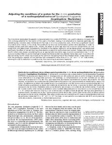
thread. This is done by analysing the WCET of all the possible paths from any point where the variable is locked to any point where it is released. As far as barriers are concerned, the longest thread is, by definition, the one that reaches the barrier last. Then this thread will not wait at this point. The approach is further detailed in [2]. To analyse the impact of the splitphase synchronisation technique on the WCETs of parallel programs, we employed two different parallelised programs. A data-parallel version of a matrix multiplication (matmul), and a data-parallel, consumer-producer Integer Fast-FourierTransformation (IFFT). We use a dynamically partitioned version of matmul, that is the matrix multiplication A = B · C, which has been partitioned into working units consisting of scalar multiplications in row i of Aij = Bi · Cj . Each row is computed by one thread, and getting the next row/working unit is secured by either a mutex lock, a binary semaphore, or alternatively a ticket lock. Matmul can be usually parallelised rather simple without any locks, e.g. statically. However, we have chosen a dynamically partitioned version to study the effects of different software synchronisations and the split-phase synchronisation technique of a parallelised program with a rather balanced synchronisation to computation ratio. The IFFT program has been parallelised based on an integer version of the iterative radix-2 algorithm, which is working in place and stores all samples in an array. In our parallelised version, for N samples the pairwise combination and rearranging in each of the k = log2 (N ) stages is done in parallel. Each thread combines independently a pair of samples, and, as in the above version of the matmul program, the fetching of the next working unit is secured using a mutex lock, a ticket lock, or respectively a binary semaphore. After each stage, we use a barrier to assure that all threads finished their computation for the current stage before beginning to compute the results in the next stage. The barriers have been implemented either using F&I barriers, or accordingly the subbarrier implementation. Details on the used synchronisation techniques are in [1]. E. Results Wilhelm et al. [27] define timing predictability of a realtime system as the difference between an estimated lower bound and an estimated upper bound, with lower bound ≤ BCET ≤ W CET ≤ upper bound. In other words, if the upper bound can be estimated as tight as possible to the unknown WCET, while the lower bound is not changing, the timing predictability increases. Also, they define worst-case performance as the real, but unknown, WCET, and worst-case guarantee as the estimated upper bound. We define the WCET CETnew improvement as W W CETref , where W CETnew is the estimated upper bound of a program’s version for that we calculate the WCET improvement, whereas W CETref is the estimated upper bound of the program’s reference implementation. For example, the reference upper bound could be the estimated WCET of a single-threaded program, whereas the W CETnew is the estimated WCET of an n- threaded implementation of that program.
We do not estimate lower bounds, and therefore we cannot make assumptions on the timing predictability as defined in [27]. For instance, with reference to the previous example, it might be possible to achieve better lower bounds for the n-threaded program than for the single-threaded one, thus the timing predictability might not change when getting lower upper bounds. However, for dimensioning a HRT system, usually only the worst-case guarantee is taken into account. Hence, achieving an improvement of worst-case guarantees could decrease the costs for over-dimensioning such a HRT system. For this reason, we delineate in this paper the improvement of worst-case guarantees of parallelised HRT programs with different synchronisation techniques, and with and without the split-phase synchronisation technique. The presented WCET estimates in Table II, that is the estimated upper bounds, have been derived from the WCET model of the MERASA quad-core processor. The parallel programs have been implemented with three kinds of primitives to guard critical sections: mutex locks, binary blocking semaphores and ticket locks. In addition, IFFT includes synchronisation barriers and was compiled with barriers implemented using subbarriers and conditionals [29] or F&I instructions. Details on the used synchronisations have been already presented in [1], and here we focus on the impact of the split-phase synchronisation technique on the WCET improvement of those parallel programs. Fig. 6 depicts the WCET improvement of the analysed four-threaded IFFT program. The WCET improvement is normalised on the reference WCET estimate derived from the parallelised IFFT with mutex locks, conditional subbarriers, and without the split-phase synchronisation technique. On the one hand, F&I barriers outperform subbarriers, and ticket locks outperform binary semaphores and mutex locks, but the main point is the improvement of WCET guarantees when using the split-phase synchronisation technique. The results in Table II show an improved estimated WCET when using the split-phase synchronisation technique of up to 1.23 (with ticket locks) for the IFFT program with conditional subbarriers, and a WCET improvement of up to 1.26, with F&I barriers and ticket locks. From Table II, the WCET improvemet for matmul with the split-phase synchronisation is up to 1.47, that is for the matmul program with ticket locks. Overall, when taking all software synchronisations into consideration, the WCET improvement using the split-phase synchronisation technique is up to 2.9 for the parallelised IFFT TABLE II WCET ESTIMATES (# CYCLES ) OF PARALLELISED HRT PROGRAMS ANALYSED ON A QUAD - CORE MERASA PROCESSOR WITH AND WITHOUT THE SPLIT- PHASE SYNCHRONISATION TECHNIQUE APPLIED . Parallelised program matmul (DIM=30) - with split-phase (DIM=30) IFFT (conditional subbarriers) - with split-phase IFFT (F&I barriers) - with split-phase
mutex 1,347,342 1,053,267 233,921 195,734 156,664 134,164
semaphore 1,041,525 832,725 196,085 171,470 110,529 103,320
ticket lock 938,312 639,332 183,936 147,360 102,252 80,688
2.9 2.3
ticket lock
1.6 1.3 2.3 2.1
semaphore
1.4 1.2 1.7 1.5
mutex lock
1.2 1 1
1.5
2
2.5
3
WCET Improvement for parallelised IFFT basic (subbarrier) basic (F&I barrier)
split-phase (subbarrier) split-phase (F&I barrier)
Fig. 6. WCET improvements on a quad-core MERASA processor for the parallelised IFFT using three different software synchronisations, and the augmented memory controllers with and without split-phase synchronisations.
program, that is the IFFT version with conditional subbarriers, mutex locks and without the split-phase synchronisation technique compared to the IFFT version with F&I barriers, ticket locks, and with the split-phase synchronisation technique used. For matmul there is a similar WCET improvement of up to 2.1 for the version with ticket locks and split-phase synchronisation technique used, compared to the matmul version with mutex locks and without the split-phase synchronisation technique. VI. C ONCLUSION Future performance requirements of safety-critical systems will soon motivate the design of parallel programs running on multi-cores. However, this will require predictable hardware and software support, in particular to implement safe and efficient inter-thread synchronisation. Also, parallel programs introduce pessimism in the WCET, because of the lack of information on synchronisation and waiting times. In this paper, we investigate a solution for such problems in HRT capable multi-core processors with the split-phase synchronisation technique. True to the motto “make the frequent case fast”, the split-phase synchronisation technique reduces the WCMLs of frequent loads/stores while sacrificing the worst-case performance of RMW operations. We show that implementing such a technique in hardware is possible, and that consistency and atomicity is maintained. We evaluate the gain in the worst-case guarantees of different parallelised HRT programs as WCET improvement, and the split-phase synchronisation achieves WCET improvements of up to 2.9 for a parallelised IFFT program.
As future challenges to further reduce the pessimism and effort in static WCET analyses of parallelised HRT programs, we see the need of an integrated approach of e.g. developing parallel programs with parallel design patterns [30] which also provide some sort of annotations for the static WCET analysis. In that way, for instance, the pessimism introduced by the problem of not knowing when what happens in parallel programs, especially for concurrent accesses to shared resources, should be further reduced. Also, the use of parallel design patterns should help programmers to better estimate the impact of the program’s design on its functional and non-functional behaviour. In [31], the authors claim that upcoming and today’s standards, e.g. ISO-26262 in the automotive domain, require to prove the correctness of non-functional behaviour, that is timing. We think that the use of timing analysable multicore processors and the support of predictable HRT capable synchronisation techniques in the RTOS is mandatory for providing safe and low WCET guarantees with static WCET analysis tools. For those reasons, we plan to investigate in our future work how selected parallel design patterns could provide significant information to improve the WCET analyses of parallel HRT programs. Also, we intend to implement HRT capable, timing predictable implementations of lockfree and wait-free data structures and evaluate their impact on the WCET guarantee in parallel programs. This might be especially of high interest for future multi-core architectures with high core numbers, which are not connected over a shared bus, but a network-on-chip (NoC). ACKNOWLEDGMENTS Part of this research has been supported by the EC FP7 project parMERASA under Grant Agreement No. 287519. R EFERENCES [1] M. Gerdes, F. Kluge, T. Ungerer, C. Rochange, and P. Sainrat, “Time Analysable Synchronisation Techniques for Parallelised Hard Real-Time Applications,” in Proc. of Design, Automation and Testing in Europe (DATE’12), March 2012, pp. 671 – 676. [2] C. Rochange, A. Bonenfant, P. Sainrat, M. Gerdes, J. Wolf, T. Ungerer, Z. Petrov, and F. Mikulu, “WCET Analysis of a Parallel 3D Multigrid Solver Executed on the MERASA Multi-Core,” in 10th Int’l Workshop on WCET Analysis (WCET 2010), vol. 268, July 2010, pp. 92–102. [3] C. Ballabriga, H. Cass´e, C. Rochange, and P. Sainrat, “OTAWA: An Open Toolbox for Adaptive WCET Analysis,” in Software Technologies for Embedded and Ubiquitous Systems, 2011, vol. 6399, pp. 35–46. [4] T. Ungerer, F. Cazorla, P. Sainrat, G. Bernat, Z. Petrov, C. Rochange, E. Quinones, M. Gerdes, M. Paolieri, J. Wolf, H. Cass´e, S. Uhrig, I. Guliashvili, M. Houston, F. Kluge, S. Metzlaff, and J. Mische, “MERASA: Multicore Execution of HRT Applications Supporting Analyzability,” IEEE Micro, vol. 30, pp. 66–75, 2010. [5] M. Monchiero, G. Palermo, C. Silvano, and O. Villa, “An Efficient Synchronization Technique for Multiprocessor Systems on-Chip,” in Proc. of MEDEA, 2005, pp. 33–40. [6] S. Liu and J.-L. Gaudiot, “Synchronization Mechanisms on Modern Multi-core Architectures,” in Advances in Computer Systems Architecture. Springer Berlin/Heidelberg, 2007, vol. 4697, pp. 290–303. [7] M. Paolieri, E. Quinones, F. Cazorla, and M. Valero, “An Analyzable Memory Controller for Hard Real-Time CMPs,” Embedded Systems Letters, IEEE, vol. 1, no. 4, pp. 86 –90, dec. 2009. [8] B. Akesson, K. Goossens, and M. Ringhofer, “Predator: A Predictable SDRAM Memory Controller,” in Proc. of the 5th Int’l Conf. on HW/SW Codesign and System Synthesis (CODES+ISSS’07), 2007, pp. 251–256.
[9] J. Reineke, I. Liu, H. D. Patel, S. Kim, and E. A. Lee, “PRET DRAM controller: bank privatization for predictability and temporal isolation,” in Proc. of the 7th IEEE/ACM/IFIP Int’l Conf. on Hardware/Software Codesign and System Synthesis (CODES+ISSS’11), 2011, pp. 99–108. [10] A. Gustavsson, A. Ermedahl, B. Lisper, and P. Pettersson, “Towards WCET Analysis of Multicore Architectures using UPPAAL,” in Proc. Int’l Workshop on WCET Analysis (WCET 2010), 2010, pp. 103–113. [11] M. Paolieri, E. Qui˜nones, F. J. Cazorla, G. Bernat, and M. Valero, “Hardware Support for WCET Analysis of Hard Real-Time Multicore Systems,” in Proc. 36th Int’l Symposium on Computer Architecture (ISCA09), 2009, pp. 57–68. [12] M.-K. Yoon, J.-E. Kim, and L. Sha, “Optimizing Tunable WCET with Shared Resource Allocation and Arbitration in HRT Multicore Systems,” in Real-Time Systems Symposium (RTSS’11), 2011, pp. 227–238. [13] A. Andrei, P. Eles, Z. Peng, and J. Rosen, “Predictable Implementation of Real-Time Applications on Multiprocessor Systems-on-Chip,” in 21st Int’l Conf. on VLSI Design (VLSID 2008), jan. 2008, pp. 103 –110. [14] A. Schranzhofer, J.-J. Chen, and L. Thiele, “Timing Analysis for TDMA Arbitration in Resource Sharing Systems,” in Real-Time and Embedded Technology and Applications Symposium (RTAS), 2010, pp. 215–224. [15] J. Staschulat, S. Schliecker, M. Ivers, and R. Ernst, “Analysis of Memory Latencies in Multi-Processor Systems,” in 5th Intl. Workshop on WorstCase Execution Time (WCET) Analysis, 2007. [16] J. Wolf, M. Gerdes, F. Kluge, S. Uhrig, J. Mische, S. Metzlaff, C. Rochange, H. Cass´e, P. Sainrat, and T. Ungerer, “RTOS Support for Parallel Execution of Hard Real-Time Applications on the MERASA Multi-core Processor,” in Proc. of IEEE ISORC’10, 2010, pp. 193–201. [17] J. Mische, I. Guliashvili, S. Uhrig, and T. Ungerer, “How to Enhance a Superscalar Processor to Provide Hard Real-Time Capable In-Order SMT,” in Proc. 23rd Int’l Conf. on Architecture of Computing Systems (ARCS’10), vol. 5974, February 2010, pp. 2–14. [18] S. Metzlaff, I. Guliashvili, S. Uhrig, and T. Ungerer, “A Dynamic Instruction Scratchpad Memory for Embedded Processors Managed by Hardware,” 24th Int’l Conf. on ARCS, pp. 122–134, February 2011. [19] L. Lamport, “How to Make a Multiprocessor Computer That Correctly Executes Multiprocess Programs,” IEEE Trans. on Computers, vol. C28, no. 9, pp. 690 –691, September 1979. [20] M. Dubois, C. Scheurich, and F. A. Briggs, “Memory Access Buffering in Multiprocessors,” in Proc. 13th Annual Int’l Symposium on Computer Architecture, vol. 14, no. 2, June 1986, pp. 434–442. [21] S. V. Adve and M. D. Hill, “Weak Ordering - A New Definition,” in 25 years of the Int’l Symposia on Computer Architecture (selected papers), ISCA’98, 1998, pp. 363–375. [22] C. P. Kruskal, L. Rudolph, and M. Snir, “Efficient Synchronization of Multiprocessors with Shared Memory,” ACM Trans. Program. Lang. Syst., vol. 10, pp. 579–601, October 1988. [23] L. D. Molesky, C. Shen, and G. Zlokapa, “Predictable Synchronization Mechanisms for Multiprocessor Real-Time Systems,” Real-Time Systems, vol. 2, pp. 163–180, 1990. [24] G. Tian and O. Hammami, “Performance Measurements of Synchronization Mechanisms on 16PE NoC Based Multi-Core with Dedicated Synchronization and Data NoC,” in 16th IEEE Int’l Conf. on Electronics, Circuits, and Systems (ICECS 2009), December 2009, pp. 988 –991. [25] R. L. Sites, “Alpha AXP architecture,” Commun. ACM, vol. 36, pp. 33–44, February 1993. [26] D. Culler, A. Dusseau, S. Goldstein, A. Krishnamurthy, S. Lumetta, T. von Eicken, and K. Yelick, “Parallel Programming in Split-C,” in Proc. of Supercomputing ’93, nov. 1993, pp. 262 – 273. [27] R. Wilhelm, J. Engblom, E. A., N. Holsti, S. Thesing, D. Whalley, G. Bernat, C. Ferdinand, R. Heckmann, T. Mitra, F. Mueller, I. Puaut, P. Puschner, J. Staschulat, and P. Stenstr¨om, “The Worst-case Execution Time Problem—Overview of Methods and Survey of Tools,” ACM Trans. on Embedded Computing Systems (TECS), vol. 7, no. 3, 2008. [28] J. Reineke and R. Sen, “Sound and Efficient WCET Analysis in the Presence of Timing Anomalies,” in 9th Int’l Workshop on WCET Analysis (WCET 2009), 2009. [29] R. Marejka, “A Barrier for Threads,” SunOpsis - The Solaris 2.0 Migration Support Centre Newsletter, vol. Vol. 4, no. 1, November 1994. [30] B. L. Massingill, T. G. Mattson, and B. A. Sanders, “More patterns for parallel application programs,” in Proceedings of the 8th Pattern Languages of Programs Workshop (PLoP 2001), September 2001. [31] R. Johansson and T. Heurung, “ISO-26262 Implications on Timing of Automotive E/E System Design Processes,” SAE Technical Paper 200901-0743, 2009.