ELECTRON LINAC FOR MEDICAL APPLICATION. J. Bigolas, S. Getka, A. Kucharczyk, S. Kulinski, W. Maciszewski, M. Pachan, E. Plawski. A. Soltan Institute for ...
Proceedings of the 2001 Particle Accelerator Conference, Chicago
THE SW ACCELERATING STRUCTURE OF VARIABLE ENERGY ELECTRON LINAC FOR MEDICAL APPLICATION J. Bigolas, S. Getka, A. Kucharczyk, S. Kulinski, W. Maciszewski, M. Pachan, E. Plawski A. Soltan Institute for Nuclear Studies, 05-400 Otwock-Swierk, Poland Abstract The standing wave, bi-periodic, on axis coupled accelerating structure operating in π/2 mode has been designed and constructed. It will be used for a new medical electron linear accelerator with the following parameters: electron energies 6, 9, 12, 15, MeV at dose rate up to 4 Gy/min/m; electron energies for X photon generation 6 and 15 MeV at X-ray dose rate up to 3Gy/min/m.
1 INTRODUCTION The medical electron accelerators developed in our Institute during past years (NEPTUN, LIMEX, COLINE) are single X-ray energy machines. The necessity of more universal multi-energy machines has been signalled by oncological hospitals. In response the State Committee for Scientific Research put the task to develop such accelerator in Institute for Nuclear Studies where the know-how of S-band electron linac techniques and technology is mastered since a long time.
2 THERAPEUTIC LINAC REQUIREMENTS
3.1 Choice of Accelerating Structure
The basic parameters of the new medical linear electron accelerator, according to the order of the State Committee for Scientific Research, are the following: Electron energy 6,9,12, 15 MeV at dose rate up to 4 Gy/min/m. Electron energy for X photons generation 6, 15 MeV at dose rate up to 3 Gy/min/m. Distance source-isocentre 1m Electron beam diameter on the e-/X target 2 mm Irradiation field area: For electrons from 2x2 cm to 30x30 cm For photons from 2x2 cm to 40x40 cm Computerized steering for 3 modes of operation: Therapy, maintenance and investigation&measurements.
3. 6-15 MeV ACCELERATOR The new medical linear electron accelerator 6/15, being designed in IPJ by common effort of two teams: IPJ - ZdAJ and P-X (Accelerator Physics and Technology Department) will meet given above requirements: four
0-7803-7191-7/01/$10.00 ©2001 IEEE.
electron energies: 6, 9, 12 and 15 MeV for electron therapy and two electron energies 6 and 15 MeV for X-ray therapy. This large range of electron energies and required electron beam intensities create serious problems in the design and construction of compact RF accelerating structure with integrated electron gun and RF power supply. The electron beam after leaving the gun has to be passed through RF accelerating structure and 2700 bending electromagnet with possible small losses. The transverse defocusing or bending forces acting on the electron originate from space charge of the beam itself, phase dependent rf field radial component, beam induced wakefields generated in structure and the stray magnetic fields originating from magnetic fields of accelerator environment. These forces are to be overcompensated by superimposed magnetic force of external solenoids and correction coils. The beam leaving accelerating structure horizontally has to be well positioned vertically and focused on e/X converter or scattering foil of collimator head. The results of analysis of these problems and methods of their solutions were presented in [1,2] and the chosen one is briefly reported here.
The designed and constructed SW S-band accelerating structure is operating at 2998.5 MHz. It is biperiodic π/2 mode, on axis coupled structure and is composed of 29 accelerating cells. To get good phase acceptance and cover large electron energy variaton from 6 to 15 MeV, the first few cells have graded beta between 0.65 and 0.95. Additionally the value of electron gun energy is adjusted for each of output energies. To fix the RF parameters of the structure, the SUPERFISH code [3] was used. The focusing solenoid of special type and system of correction coils surrounding the structure, guide the beam on axis.
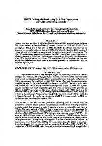
3.2 The electron beam dynamics The longitudinal and transverse beam dynamics in 6-15 MeV linac were studied using the codes [4,5] developed for the purpose in our Laboratory. The dependence of beam output energy and transverse dimension on the RF input phase at optimal values of magnetic field of solenoid are shown in Fig.1 and Fig.2. To minimize the magnetic field on gun cathode, the bucking coil (Fig.3) is added at input of solenoid. This
2790
Proceedings of the 2001 Particle Accelerator Conference, Chicago substantially improves the action of iron magnetic shield placed inside the input side of accelerating structure.
Energy
12
aperture limit
4.0
Rout
6 2
0.0 -275
-250
-225
-200
-175
RF input phase [deg]
0
-150
12.0
20.0 17.5
Energy
12.5
16.0
20.0
z[cm]
24.0
28.0
Torr). The advantage of triode over diode gun is independent regulation of gun current and energy at much lower heater power and lower anode voltage. The gun dimensions are reduced at least twice. The measuring, high vacuum stand equipped with the wire scanners was built to measure and verify the calculated optical parameters.
Run 15m; 29cells/Bet .65,.65,.7,.75,.85,.95,1.. Erf=25 MV/m, Bsol=1500Gs, Uin=15.5keV/0.2A/ Rin=1.1mm/38mrad
15.0
Magn. Screen inside structure
Fig. 3 Solenoid magnetic field at input side of accelerator structure
Fig.1 Output energy and beam size at RF field level corresponding to 6 MeV energy.
10.0
10.0
7.5
Triode gun for 6-15MeV electron linac
aperture limit
5.0 2.5
Rout
r[mm]
Energy[MeV], Beam out [mm]
B/Bmax*10
8 4
2.0
䡩㛭 㛬⽧ 你
⭋⻫●⽦夝 ●㛭 㛬⽧
10
Gun cathode position
6.0
Normalized axial magnetic field distribution in long screened solenoid
14
Run/ 6m; 29cells; Bet .65,.65,.7,.75,.85,.95,1... . Erf=9.6 MV/m, Bsol=750 Gs, Uin=12keV/0.2A/Rin=1.26mm/47mrad
B/Bmax
Energy[MeV], Beam out [mm]
8.0
16
0.0 -275 -250 -225 -200 -175 -150
5.0
RF input phase [deg] Anode
Fig. 2 Output energy and radial beam size at RF field corresponding to 15 MeV.
0.0 0.0
3.3 Electron Gun In up to now medical electron accelerators built in Poland: Neptun, Limex, Coline the source of electrons (gun) was diode with thermionic cathode made of tungsten. For the new 6/15 medical accelerator the final solution will be a triode gun. For that purpose spherical cathode - grid assembly was bought with the following nominal data claimed by the producer: grid cut off = -60V, griddrive = +60V for 1A at Ua=12kV; grid current=12%Ic, gridload =1Wmax; heater 6.3V/2.0A; Pulse width 100µsec max, duty cycle 0.04 max is allowed. The cathode material is of dispenser type. The vacuum conditions for this type of cathode are rather severe (better than 5x10⁻⁷
5.0
z[mm]
10.0
15.0
Fig. 4 Triode GUN. Ua=12kV, Ug=60V, I=0.4A
3.4 The RF system The RF power is delivered to accelerating structure from klystron amplifier TH 2074A excited by vacuum tube tunable pilot oscillator. The RF power is transmitted to the accelerating structure through the rectangular waveguide WR284 with incorporated 4-port ferrite circulator attenuating the reflected wave on the level
2791
Proceedings of the 2001 Particle Accelerator Conference, Chicago -39dB. The additional reflector is included in the waveguide chain with the aim to control the power transmitted to the structure through controlled reflection of some its part back toward circulator load. The range of
e-
RF power regulation is from Pmax to 0.3Pmax and enables the electron beam energy variation in designed range. The coaxial rotary joint of choke type is used as an interface to rotating gantry of accelerator.
E=6-15 M eV
AC CEL ER AT IN G SEC T IO N
B UN CH IN G SEC T IO N
H V -D C SUPPLY O2
HY BRID RING
M O D UL PH AS E SH IFT ER
R EFL EC T O R
D ET . 2 RF
A.F.C
RF
CIRC .
L OAD -1
3
1
PULSER
LO AD -2
4
SF6 KLY ST R . 5 MW
M AST ER O SC IL L.
Fig. 5 RF-system for 6/15 MeV accelerator The automatic frequency control system (AFC), consists of hybrid ring, phase shifter, detector and electronic steering circuit. It matches the frequency of pilot oscillator to operating frequency of accelerating structure. The block diagram of the system is shown in Fig. 5 and the basic parameters are given in table below Operational frequency Range of pilot control Pilot RF power (in pulse) Klystron peak RF power Pulse length Repetition rate
4. REFERENCES [1] Annual Report 1999 of Institute for Nuclear Studies p.172 [2] Annual Report 2000 of Institute for Nuclear Studies [3] “Poisson Superfish”, J.H. Billen,L.M. Young, LA-UR-96-1834 Rep. , Los Alamos ,Nov.1996 [4] Program LISA, S. Kulinski, To be published . [5] “ELINAC code”, E. Plawski, Inst. For Nuclear Studies, Internal Rep. To be published.
f =2998.5 MHz ∆f = ± 5 MHz 120 W max 6 MW 5 microsec 12.5 - 300 Hz
2792