Construction and demolition debris results from building and demolition activities, it includes concrete, asphalt, wood, bricks and glass. The landfills are not ...
American International Journal of Contemporary Research
Vol. 2 No.10; October 2012
The System Dynamics Modeling Method in Application of Geo-Membranes as Landfill Liners S.O. Ojoawo A.A. Adegbola Department of Civil Engineering Ladoke Akintola University of Technology P.M.B 4000, Ogbomoso, Nigeria.
Abstract This paper examines the performance of geo-membrane materials as landfill liners using the system dynamics modeling approach. The study area is Ogbomoso North Local Government Area of Oyo State, Nigeria. Four (4) materials were studied, these include: Smooth High Density Polyethylene (HDPE), Textured HDPE, Smooth Low Density Polyethylene (LDPE) and Textured LDPE. The main properties of focus on the material were hydraulic conductivity, porosity and thickness. A model was developed by applying the governing equations coded in Visual Basic Computer programming Language. Validation of the model was done with data on the study area. The interrelationship of the properties and the breakthrough times for each material was found through the STELLA 9.1.4 software application. It was found from this research that the effectiveness of the studied geo-membrane material liners is of the order Smooth HDPE > Smooth LDPE > Textured HDPE > Textured LDPE. The Smooth HDPE is therefore recommended for use as landfill liner in the study area.
Keywords: System dynamics, Geo-membrane, liner, Landfill, Ogbomosoland, I. Introduction Geo-membranes are impermeable geo-synthetic materials widely used as landfill liners to control leachate pollution of underground water. Leachate is generated when there is excess water passing through stored waste mass dissolving soluble substances. Bottom liners of landfills may contain one or more layers of Clay or a synthetic flexible membrane (or a combination of these). As such the common liners include Compacted Clay, CC and Geo-synthetic Clay, GC [1]. The control of leachate emanating from landfills can be accomplished either by preventing the precipitation from entering the refuse using appropriate covers or through a more realistic approach of containment/barrier and collection system [2]. Since it may be practically difficult to shield landfill dumps totally from precipitation, the leachate containment is therefore mostly considered and adopted. Liners for the management of leachate are made in form of containment and are targeted at limiting the migration of contaminants into the surrounding environment to levels that will result in negligible pollution impact [3]. One of the largest current applications of geo-membranes is at the landfill sites for the containment of wastes and their leachates. Generally speaking, Landfill liners are intended to be a low permeable barrier which is laid down under engineered landfill sites. Landfill liners are designed and constructed to create a barrier between the waste and the environment and to drain the leachate to collection and treatment facilities. This is done to prevent the uncontrolled released of leachate into the environment [4]. Furthermore, [5] also reported that landfill liners until it deteriorates, it retard migration of leachate, and its toxic constituents, into underlying aquifers or nearby rivers, causing spoliation of local water. Modern landfill generally requires a layer of compacted clay with a minimum required thickness and maximum allowable hydraulic conductivity overlaid by a high-density polyethylene geo-membrane [6]. The United State Environmental Protection Agency discovered that the barriers will ultimately fail „threat for thousands of year‟ suggesting that modern landfill design delay but do not prevent ground and surface water pollution and hence chipped or waste tires are used to support and insulate the liner. 138
© Centre for Promoting Ideas, USA
www.aijcrnet.com
The society produces many different solid wastes that posed different threats to the environment and to community health and different disposal sites are available for these different types of waste. The potential threat posed by the waste determine the type of liner system required to as simple, composite and /or double liner. Single layer consist of clay liner, a geosynthetic clay liner or geomembrane (specialized plastic sheeting). Singles liners are sometimes used in landfills designed to hold construction and demolition debris (C and D) [7]. Construction and demolition debris results from building and demolition activities, it includes concrete, asphalt, wood, bricks and glass. The landfills are not constructed to contain paint, liquid, tar, municipal garbage or treated lumber, consequently, single liner system are usually adequate to protect the environment. It is easier to dispose of construction material in C and D landfill than in municipal solid waste landfills. The use of single liner is easier to building and maintain than other types [7]. A composite liner consists of a geo-membrane in combination with a clay liner. Composite liner systems are more effective at limiting leachate migration into the sub-soil than either a clay liner or a single geo-membrane layer. Hence composite liners are required in municipal solid waste landfills. A double liner could either be two single liners, two composite liners or single and a composite layer. The upper or primary liner usually function tom collect the leachate whole the lower or secondary liner acts as a leak detection system and a back-up to the primary liner [5]. Double-liner systems are used in some municipal solid waste landfills and in all hazardous waste landfills. Hazardous waste landfills (also referred to as secure landfill) are constructed for the disposal of waste that once were ignitable, corrosive reactive, toxic or are designed as hazardous [8]. Geo-membrane liners are made of high density polyethylene to ensure maximum security of the solid waste contaminant. There are a variety of choices of geo-membrane liners that the liner companies manufacture to suit the needs of the lining system. The simplest difference that is offered is geo-membranes which are textured or smooth. A smooth geo-membrane liner is normally used for collection ponds since they are not covered with soil or other liners. Collection ponds also do not have steep side slopes which results in minimal slipping if additional liners are placed. A textured geo-membrane is typically used for mining and solid waste landfills. This creates a surface for additional layers such as geo-composite or soil to adhere to and releases pressure from the seams of the liner [9]. Other types of geo-membrane liners that are available are white geo-membranes, which will cut back on thermal expansion and also create a cooler environment for the workers due to light reflection. This type of geo-membrane is typically used in solid waste landfills. A flame retardant geo-membrane is available from certain companies. It can be used in areas such as nuclear facilities and petrochemical applications. Finally, there is a conductive geo-membrane that has been made available by the GSE Lining Company. This liner can be used for a collection pond and provides a simple procedure to test for damages. This is accomplished by using a unique type of spark testing. This was constructed for collection ponds that are exposed to the elements and have increased chances for damage. The primary use of the geo-membrane liner is to contain the contaminants of solid waste. Of the commonest landfill liners, geo-membranes have been reported to possess highest durability of between 50 to 65 years [10]. The central aim of this paper is to model the applications of Geo-membranes as landfill liners using the system dynamics method. The selected case study is Ogbomoso North Local Government Area (LGA) of Oyo State Nigeria. Ogbomoso North LGA has an average population of 198,720 going by National Population Commission, NPC cencus [11]. It lies approximately on Longitude 4 0 15‟ East, Latitude 8 0 07‟ North and situated in the transitional zone between rain forest and savannah region [12].
II. Methodology (1) The material: Geo-membrane liner systems of leachate management were applied in this study. Four (4) different types of geo-membrane liner containments were examined, these are: Smooth High Density Polyethylene (HDPE), Textured HDPE, Smooth Low Density Polyethylene (LDPE) and Textured LDPE. The properties studied and employed in data validation as presented in Table I on these liners were: (i) Hydraulic conductivity (ii) Porosity (iii) Thickness (iv) Maximum slope 139
American International Journal of Contemporary Research
Vol. 2 No.10; October 2012
(2) Governing Equations: The principal governing equations for the model are as follows (a) For leachate generation, as given by [13] N cells LQnT (nΔt) = W4(t) – Wg(t) + Σ
LQn( i, (n – i + 1) Δt i=1
-------(1)
where LQnT = Accumulative amount of leachate generated from the system nΔt = No of waste cells at the given time W4 = Overall mass of water entering or leaving the dumpsite Wg = Total water loss due to degradation LQn = Overall leachate quantity generated from a single cell n & i = Counters t = Breakthrough time of the liner d = Thickness of the liner α’ = Effective porosity K = Coefficient of permeability and h = Hydraulic head (b) Breakthrough time, t according to [14] is t = d2α’ / K( d + h)
---------------------- (2)
where d = thickness of the liner (m) α’ = effective porosity K = coefficient of permeability (m/s) (c ) Leackage rate through the liners qi, as again given by [14] is determined from: qi = K [ 1 + y cos ϕ ] d ------- (3) where K = coefficient of permeability (m/s) d = liner thickness (m) ϕ = the liner slope (measured in angles) y = the leachate depth over liner (m) Table I: Validation Data for the Geo-Membrane Samples Material
Smooth HDPE Textured HDPE Smooth LDPE Textured LDPE
Hydraulic Conductivity (x 10-9) m/s 0.58 0.93 0.81 1.16
Porosity
Thickness (m)
Maximum slope
0.62 1.75 2.27 1.85
0.004 0.005 0.002 0.003
16 16 16 16
Source: [1]; [15]); and [16] 140
© Centre for Promoting Ideas, USA
www.aijcrnet.com
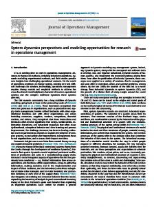
(3) Computer programming and Simulation: The Visual Basic language was employed in coding the equations. The key elements of the Model were defined and quantified as variables. These variables include hydraulic conductivity, porosity, liner‟s thickness and slope. Their relationships were formulated mathematically and the system dynamics structures applied in developing the source codes. Once the parameters and the initial values for the State Variables (Stocks) were specified, the model became definitively determined through the program. The stock flow diagram of the system was designed using STELLA 9.1.4 software and simulation package. The principles of system dynamics were applied to determine the interrelationships of leachate a n d G e o - m e m b r a n e l i n er s retention ability. These were simulated to predict the results for the next 50 years using year 2006 data as initial values in the stocks of the flow diagram. Causal loops indicating the linkage of leachate generation and variables with the breakthrough time were developed. The STELLA flow diagram of the model is shown in Fig 1. (4) Validation of the model: To compare the model results with historical data and to check whether the model generates plausible behavior there is need for its validation. The developed model was validated by applying it in t he assessment of practical problems of leachate pollution containment with Geo-membranes in Ogbomoso North LGA.
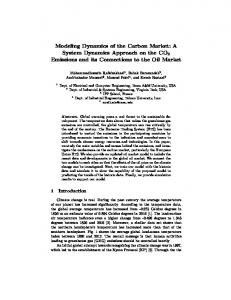
III. Results and Discussion The results of the simulation for 100 years performance of the studied geo-membranes depicting the behavioural patterns one year after the other are as presented in Figures 2 to 5 below: 1: Selected Breakthrough Time 1:
23526458
1:
23526458 1
1 1
1
1:
23526458 0.00
Page 1
25.00
50.00 Time (y rs)
75.00
100.00
10:33 PM Sun, Apr 15, 2012
Fig 2. Breakthrough time graph of Smooth HDPE
From figure 2, it was observed that the breakthrough time (i.e the time it would take the modeled quantity of leachate to penetrate the given liner material) for the Smooth HDPE is 23,524,658 seconds or 273 days. The respective durations for Textured HDPE; Smooth LDPE; and Textured LDPE as depicted in figures 3 to 5 are 10,190,915 seconds (118 days); 10,194,942 seconds (119 days) and 10,185,531 seconds (117 days). Table II presents this result at a glance.
141
American International Journal of Contemporary Research
Vol. 2 No.10; October 2012
Death Rate
BirthRate Population ?
?
Births
Deaths
Estimated Population Total Precipitation ?
Runoff Coefficient
Total Waste Generated
?
Effective Precipitation Actual Evapotranspiration Correction Factor ?
Initial Dry Weight of SW
?
?
Primary Leachate
Overall leachate Quantity for Single Cell
Overall mass of Water Entering or Leaving Dumpsite
Gas Generation Rate Decay Process
Chemical Reaction ?
Moisture Content of Waste Water Consumption Due ?
?
Field Capacity To Waste Decomposition
?
Mass of Water Consumed per Cubic Meter of Ga Produced Decreasing
?
Initial Field Capactiy
Accumulative Amount of Lechate
Effective Porosity Coefficient of Permeability Breakthrough Time Hydraulic Head
Rate of Leakage
Saturated Vertical
Hydraulic Conductivity Liner Slope in angle ?
Thickness of Liner
Fig 1. The Stella flow diagram of the model Table II: Breakthrough Times of the Studied Geo-Membranes Material Smooth HDPE Textured HDPE Smooth LDPE Textured LDPE 142
Breakthrough time (s) 23,524,658 10,190,915 10,194,942 10,185,531
Breakthrough time (day) 273 118 119 117
© Centre for Promoting Ideas, USA
www.aijcrnet.com
The Smooth HDPE will therefore have the highest retention capability for the leachate volume simulated. This perhaps is linkable to the fact that it has been reported to possess the lowest water absorption rate [16]. The texture LDPE on the other hand recorded the lowest breakthrough period and thus found to be the least capable of the studied liners. 1: Selected Breakthrough Time 1:
10190915
1:
10190915
1 1 1
1
1:
10190915 0.00
25.00
50.00
Page 1
75.00
Time (yrs)
100.00
10:44 PM Sun, Apr 15, 2012
Fig 3. Breakthrough time graph for Textured HDPE
1: Selected Breakthrough Time 1:
10194942
1:
10194942 1
1 1
1
1:
10194942 0.00
25.00
Page 1
50.00
75.00
Time (yrs)
100.00
10:47 PM Sun, Apr 15, 2012
Fig 4. Breakthrough time graph of Smooth LDPE
1: Selected Breakthrough Time 1:
10185531
1:
10185531
1 1 1
1
1:
10185531 0.00
Page 1
25.00
50.00
75.00
Time (yrs)
100.00
10:50 PM Sun, Apr 15, 2012
Fig 5. Breakthrough time graph for Textured LDPE
143
American International Journal of Contemporary Research
Vol. 2 No.10; October 2012
IV. Conclusion It was found from this research that the effectiveness of the studied geo-membrane material liners is of the order Smooth HDPE > Smooth LDPE > Textured HDPE > Textured LDPE. The longest breakthrough period discovered for the application of geo-membrane liners in Ogbomoso North LGA of Nigeria was 273 days. The study therefore recommends the use of Smooth HDPE liners for landfill leachate containment in the study area.
Acknowledgments The contributions of my Research Assistants, Dauda Jamiu and Salami Babatunde on the material testing is highly appreciated. The effort of Mrs Olubunmi T. Ojoawo in the typesetting work is also very commendable.
References S.O Ojoawo “Management of leachate pollution form dumpsites in ogbomosoland”. Unpublished Ph.D Thesis, Faculty of Technologyy, University of Ibadan, Ibadan, Nigeria, pp 51-52, 2009. J.T Pfeffer “Solid waste management in Engineering”. Prentice Hall, pp 235 -249, 1992. R.K Rowe “Geosynthetics and the minimization of contaminant migration through barrier systems beneath solid waste” Proceedings of the 6th International Conference on Geosynthetics, pp 24 -36, 1998. L.H Kerry, A.D Christy, J.E Heimlich and K.L Shah “ Basics of Solid and Hazardous Waste Management Technology”. Prentice Hall, Upper Saddle River, New York. Pp 45-46, 2005. R.K Rowe, E.T Kerry, L.M Quigley, M.A Robert, F.J Brachman, W.I Richard, J.M Booker, and R.I John, 2nd ed., (2004) “Barrier Systems for Waste Disposal Facilities” . Prentice Hall, pp 22-25, 2004. J.O Wesseloo, A.T Visser and E.H Rust “A Mathematical Model for the Strain Rate Dependent Stress-Strain Response of HDPE Geomembranes”. Geotextiles and Geomembranes 22, No.7: 273-295, 2004. M.W Sharma, G.J Hari, D.V Reddy and O.P Krishna “Geoenvironmental Engineering: Site Remediation”, Waste Containment and Emerging Waste Management Technologies. John Wiley Sons, Inc, Hoboken, New Jersey, pp 23-24, 2004. U.S Environmental Protection Agency, Office Municipal Solid Waste Disposal 2011. Gundle Lining Systems. GSE Lining Technology. [Brochure]. Gundle Lining Technology Inc., pp 27-36, 1996. R.K Rowe and G.J Rinal “Durabiltiy of Landfill liners”. Prentice Hall, pp 4-6, 2008. NPC “Official gazette for 2006 population cencus”. National Population Commision. Nigeria, p 34, 2006. B. Edward and L.M Joel “World Atlas”. 16th ed., USA, pp 21-35, 1978 E. Safari and C. Baronian “ Modelling temporal variations in leachate quantity generated at Kahrizah landfill”. Proceedings of International Environmental Modeling Software, 482 – 484, 2002. T. Kadlec and M. Knight “Leachate management in landfills”. Environmental Hydrology, Chapter 12, 94 – 105, 1996. R.J Petrov and R.K Rowe “ Geosynthetic clay liner: chemical capability by hydraulic conductivity testing and factors impacting its performance”. Canadian Geotextile Journal, 34: 863-885, 1997. J. Dauda and B. Salami “ An investigation into the physical properties of landfill liners”. Unpublished B. Tech Project Report, Department of Civil Engineering, Ladoke Akintola University of Technology, Ogbomoso, Nigeria, pp 56-59, 2012
144


![Modeling Start-ups using System Dynamics - System Dynamics Society [PDF]](https://m.moam.info/img/260x300/modeling-start-ups-using-system-dynamics-system-dy_648bbbc3098a9e4e318b459b.jpg)


