Abstract. The TOP-IMPLART project, developed by ENEA, the ... Table 1: TOP-IMPLART Main Parameters ... in fig.1) assisted by a dedicated orientable TAC for.
THPS067
Proceedings of IPAC2011, San Sebastián, Spain
THE TOP-IMPLART PROJECT C.Ronsivalle, M. Carpanese,G. Messina,L. Picardi,S. Sandri ENEA-CR Frascati, Frascati, Italy C. Marino,ENEA-Casaccia, Rome, Italy M. Benassi,L. Strigari,IFO, Rome, Italy E. Cisbani,S. Frullani,V. Macellari, ISS, Rome, Italy
c 2011 by IPAC’11/EPS-AG — cc Creative Commons Attribution 3.0 (CC BY 3.0) Copyright ○
Abstract The TOP-IMPLART project, developed by ENEA, the Italian National Institute of Health (ISS) and Regina Elena National Cancer Institute-IFO-Rome is devoted to the realization of a proton therapy centre to be sited at IFO, it is based on a sequence of linear accelerators and designed with three treatment rooms: one with a 150 MeV beam for shallow tumors and two with a 230 MeV beam for deep tumors. The first part of the acronym remarks the heritage from the TOP Project developed in 19982005 by ISS and ENEA, whilst the second part (“Intensity Modulated Proton Linear Accelerator for RadioTherapy”) exploits the possibility to perform a highly conformational therapy based on spatial and intensity modulation of the beam. The segment up to 150 MeV, funded by the Italian “Regione Lazio” for 11M€ over four years, is under installation at ENEA-Frascati for its validation before the transfer to IFO. The low energy part is also used as a facility for radiobiology experiments in the framework of a satellite program foreseeing cells irradiation at 7 MeV by vertical and horizontal beam fields and small animal irradiation with a 17.5 MeV horizontal beam. The status of the Project is presented.
PROJECT DESCRIPTION In 2008 the TOP-IMPLART Project [1] was promoted by ENEA in collaboration with con ISS e IFO, with the aim of building a protontherapy linac to be housed in the largest oncological hospital in Rome, IFO. The facility (fig.1) is based on an accelerator consisting in a low frequency (425 MHz) 7 MeV injector followed by a sequence of 3 GHz accelerating modules and provided with three treatment rooms. The main peculiarities respect to the conventional protontherapy machines, usually based on circular accelerators, are the modularity, the use of a technology similar to the conventional
radiotherapy electron machines, a very low emittance beam, the possibility to perform active and fast energy variation and pulse to pulse current variation. The main parameters are reported in table 1. Table 1: TOP-IMPLART Main Parameters Parameter
Value
Beam energy phase 1
69-85/150 MeV
Beam energy phase 2
69-85/230 MeV
Pulse duration
1-3.5 µsec
Repetition frequency
10-100 Hz
Typical beam spot
7Hx7V mm
Normalized emittance
0.2 mm-mrad
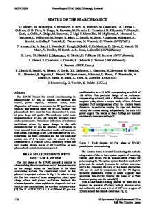
A study is undergoing leaded by a Bari Company (ITEL) to design an innovative treatment chair/bed (box in fig.1) assisted by a dedicated orientable TAC for positioning the patient. The goal is to get the same functionalities of an expensive gantry, replacing its movement by flexible patient alignment combined with one or two fixed beams. The Project foresees two phases of construction of the accelerating machine: in the first phase the maximum energy will be 150 MeV; in the second phase the system will be extended to get up to 230 MeV beam energy. In 2010 the funding of the first phase with a 11 M€ grant was approved by the Innovation Department of Regione Lazio. The phase-1 of the project will allow the use of the 150 MeV beam for therapy: at this energy the penetration depth of protons in tissue is about 15 cm and it is possible to treat at least half of the lesions eligible for protontherapy (including ocular melanoma and headneck cancers). Recently IFO-IRE has acquired a large area for the installation of the machine.
Figure 1: TOP-IMPLART layout at IFO (in the right box the treatment bed under development by ITEL). 08 Applications of Accelerators, Technology Transfer and Industrial Relations 3580
U01 Medical Applications
Proceedings of IPAC2011, San Sebastián, Spain
Table 3::CCL Parameters
TOP-IMPLART150 AT ENEA-FRASCATI
Unit 1
Unit 2
Unit 3
Unit 4
Tanks/module
8
8
6
6
Gaps/tank
16
16
16-17-16
16-17-16
Bore hole, mm
6
6
6
6
Distance between tanks /βλ
3.5
2.5
2
2
Energy, MeV
54.35
85.22
115.7
150
Length, mm
2626.12
3043.41
2604.6
2932.02
The design of the RF plant is addressed to minimize the RF modulators and RF power tubes, for simplicity and costs, but at the same time to get a flexible overall plant. It is based on the use of five 10 MW klystron (TH2157A type): the first one will supply the SCDTL modules, whilst the other four klystron will supply the four CCL units (two modules/unit).
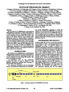
The Satellite Program ISPAN The segment up to 17.5 MeV (fig.3 left) in the test site at ENEA-Frascati will be used also in the framework of a ongoing satellite program named ISPAN funded with 570K€ by Regione Lazio-Filas aimed to setup a radiobiology facility with two beam outputs: a 17.5 MeV horizontal beam for small animal irradiation and a 3-7 MeV vertical beam pointing upwards for cells irradiation obtained by a 90° vertical bending magnet (fig.3 right) placed in an adequate space between two couples of quadrupoles used for matching the 7 MeV beam in the transverse planes to the following accelerating structure. The Project is leaded by two Italian companies NRT (already operative in the field of medical accelerators by producing electron machines for IORT) and CECOM, whilst ENEA and ISS have the role of scientific coleaders.
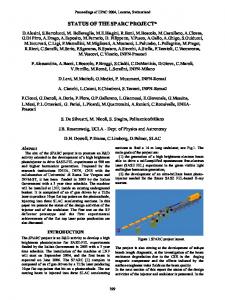
Figure 2: TOP-IMPLART150 at ENEA test site. . Table 2:SCDTL Parameters Module 1
Module 2
Module 3
Module 4
Tanks
9
7
5
5
Gaps/tank
4
5
6
6
Bore hole, mm
4
4
6
6
Distance between tanks /βλ
5.5
4.5
3.5
3.5
Figure 3: (left) ISPAN layout, (right) vertical bending magnet.
The injector is installed and running and is able to give a continuously variable energy beam from 2.7 to 7.1 MeV, achieved by varying the relative phase and/or the input rf Length mm 1108.67 1144.34 986.29 1101.81 power level of the DTL as required by the radiobiology experiments. The machining of the two SCDTL structures 08 Applications of Accelerators, Technology Transfer and Industrial Relations Energy, MeV
11.6
U01 Medical Applications
17.5
23.3
30
3581
c 2011 by IPAC’11/EPS-AG — cc Creative Commons Attribution 3.0 (CC BY 3.0) Copyright ○
The first assembly and tests of the accelerator section up to 150 MeV will be done at the Research Centre in ENEA-Frascati in a 30m long 3m wide bunker (fig.2) for full proton beam characterization and validation from the dosimetric point of view, before the relocation to IFO. The injector is a 425 MHz PL7 ACCSYS-HITACHI model (DuoPlasmatron source+RFQ+DTL) in which the current can be changed on a pulse-to-pulse basis, by using a pulsed einzel lens following the proton source. The accelerator from 7 to 150 MeV is subdivided in modules working at 2998 MHz consisting in a number of tanks divided in cells. The first four modules up to 30 MeV are of SCDTL (Side coupled DTL) type, whilst the other modules are of CCL (Coupled Cavity Linac) type. The SCDTL structure [2] consists of short DTL tanks each having 4 to 7 cells of βλ length coupled together by side cavities extending in a space left free on the axis for the accommodation of a very short (3 cm long, 2 cm o.d., 6-7 mm i.d.) demountable PMQs (Permanent Magnet Quadrupole) for transverse focusing. Tests of the CCL structure up to 41 MeV will be done on the so-called First Unit, originally designed as a 30 MeV cyclotron booster in a CYCLINAC system, manufactured by ADAM, a CERN spin-off company and transferred from CERN to ENEA in july 2011. The main parameters of TOPIMPLART150 structures are summarized in tables 2 and 3.
THPS067
THPS067
Proceedings of IPAC2011, San Sebastián, Spain
bringing the energy to 17.5 MeV is under way (fig.4) The operation is foreseen for the end of 2011.
Figure 4: Tank 1 and 9 of SCDTL module 1.
BEAM LOSSES
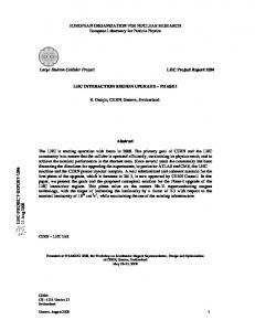
Figure 5: Computed beam transmission vs z(left) and losses vs energy (right). They are mainly due to the longitudinal mismatching between the low frequency non-synchronous injector and the high frequency accelerator because of the bunch lengthening (fig.6left) produced by the spread in speed in the low energy beam transport (LEBT). In a green-field situation (fig.6right), the PL7 injector can be replaced by a similar device, with an operating RF frequency of 428.27 MHz (the 7th sub-harmonic of 2.9979 GHz) and the distance between the injector and the booster can be reduced by the use of a compact LEBT including only 3 PMQs: in this case the low beam losses (35% transmission) and the low average energy of the lost particles suggest a locally shielded accelerator, with single output beam, able to scan the energy from max (180-200 MeV) to min (60 MeV) electronically. 300 Phase half width (deg at 2998 MHz)
c 2011 by IPAC’11/EPS-AG — cc Creative Commons Attribution 3.0 (CC BY 3.0) Copyright ○
Beam dynamics calculations show that in TOPIMPLART150 the main losses occour below 20 MeV (fig.5), when the neutron production is low [3].
250 200 150 100 50 0 0
20
40 60 80 100 120 Injector-SCDTL distance (cm)
ENERGY VARIATION The energy is varied by changing the power of the klystrons supplying the accelerator structure. The TOPIMPLART claims to change the beam energy as quickly as possible, although, as in other PT plants the limiting factor is the velocity of changing the beam transport line magnetic elements, and this is commonly set to 0.1 sec/slice. The energy can be varied continuously in a range between 85 and 150 MeV using the last four modules named CCL3A, CCL3B, CCL4A, CCL4B, by switching off the last modules and varying the electric field amplitude in the last active module from 0 to 100% (fig.7 left). Above 85 MeV each module provides an energy gain of 15 - 16 MeV. This modest energy gain allows the acceleration of the beam also at lower field levels than the nominal one, although some mismatching occurs in the transverse and longitudinal dynamics. It has been proven by extensive calculations that 15 MeV per module is an upper limit for the energy gain that does not prevent at all the beam transmission when the last module is powered at low fields levels. In fig.7 (right) the computed RMS energy spread versus the average output energy is shown at different energies. The solid curve represents the tolerated RMS energy spread corresponding to a monochromatic beam and a distal falloff of 2 mm. The final energy spread inside the patient will be a quadratic sum of the two contributes.
Figure 7: (left) Average energy vs the electric field amplitude in the last switched on module, (right) RMS energy spread compared with the limiting curve. The energy variation is obtained by using the last two klystrons each one combined with a balancer, placed in the RF lines after the circulator: it is composed by a sequence of a 3 dB hybrid, a phase shifter, another 3 dB hybrid, and another phase shifter, this scheme allows to divide the power in two branches, managing amplitude and phase in each of them. Despite the numerous controls, this system is expected to be relatively inexpensive, since only commercial passive RF components are used. The expected variation speed is not so high (≥100 msec), but is considered adequate to the scope of the prototype.
140
Figure 6: (left) bunch lengthening (right) SCDTL output transmission vs distance injector-SCDTL The heavy shielding would only be necessary for the treatment room. This arrangement seems to be the optimized setup for the lowest cost protontherapy plant.
REFERENCES [1] C. Ronsivalle et al. “The TOP-IMPLART Project”, Eur. Phys. J. Plus (2011), 126, number 7, 68 [2] Patent N. RM95-A000564, 9/9/; Inventors L. Picardi, C.Ronsivalle, A. Vignati, Owner: ENEA [3] S.Sandri et al.,”A proton therapy facility:the radiation protection design”, these Proceedings.
08 Applications of Accelerators, Technology Transfer and Industrial Relations 3582
U01 Medical Applications