UIMS and UI design environments, end-user programming, prototyping, interaction ... build robust realizations of what they envision as the best that the digital ...
The Tower System: A Toolkit for Prototyping Tangible User Interfaces Bakhtiar Mikhak, Christopher Lyon, Tim Gorton Grassroots Invention Group MIT Media Lab 20 Ames Street Cambridge, MA 02139, USA {mikhak, scooby, tgorton}@media.mit.edu ABSTRACT
A key strength of the CHI community is its focus on realizing designs through the construction of functioning prototypes. However, building such prototypes of tangible user interfaces (TUIs) currently requires considerable technical knowledge and typically has a long development cycle. As the CHI community continues to expand and include practitioners from a broader range of backgrounds, there is a growing need to provide our community with a powerful, flexible, and extensible toolkit for the rapid prototyping of TUIs. To meet the needs of the most demanding applications, we have created the Tower system, which includes a wide variety of hardware modules and software libraries for sensing, actuation, communication – including Ethernet, IR, and RF – and visual and audio output. Furthermore, we provide technically experienced designers with the hardware and software tools to incorporate new functionality into the system with relative ease. Keywords
Development tools, toolkits, programming environments, UIMS and UI design environments, end-user programming, prototyping, interaction design, ubiquitous computing and smart environments, software architecture and engineering.
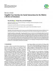
Figure 1: The Tower practitioners and educators who continually design and build robust realizations of what they envision as the best that the digital revolution can offer – plays a critical role in guiding these efforts.
INTRODUCTION
Infusion of computation into every aspect of our lives is inevitable, but the forms that computation will take is an active area of research and will be shaped by people’s needs and desires in the variety of contexts in which they live, work and play. By the end of this decade, computers will be embedded in everyday objects all around us: our home appliances and furniture, our communication and transportation devices, and even our books and our clothing. In this time of rapid change, the CHI community – as a premier interdisciplinary group of researchers,
Rapid prototyping is at the heart of the vitality of the CHI community and it is what distinguishes us as a group that is interested in the quality of human experiences in a technology rich world. The best works from our members highlight the idea that one of the most exciting times in the life of any technology is the point at which artists and designers elevate it to a true medium of expression and use it to create the kind of experiences that celebrate the things that makes us uniquely human. From that point on, the evolution of a technology that enjoys such a success is often deeply intertwined with the expectations and sensibilities of the artists and designers who are pushing the limits of the medium to realize its full creative potential. [1, 2, 5, 8] As it is immediately evident when one reviews the best ideas that our community has produced, many CHI
-1-
designers have seized the opportunity afforded by newly available technologies to produce more and more responsive and interactive artifacts and spaces. In their new designs, they pay close attention to the quality of the behaviors and modes of interaction as well as to the aesthetics of the static structures they create. Computation, while enriching the range of functions offered, makes it more challenging to achieve harmony between form and function. A new generation of technically savvy designers has emerged to embrace this challenge and is actively expanding and fundamentally rethinking traditional guidelines for good design.
applications. In addition to building self-contained hardware modules with simple programming interfaces, we drew upon the long tradition of research in using the Logo programming language with novices. We also insisted that the design of the Tower system be modular wherever possible in order to provide for future expansion of hardware and software components, as well as making it possible to use only the functionality needed for any particular application. This also allows novices to build fluency with the system by providing a path for them to explore the components of the system. Transparency has also been an important principle of the design to illuminate what components of the system are easily modifiable by end-users and what design choices make this possible. Our aim is to help users understand how the system can be made to fit their requirements and provide paths for doing so.
This clearly is an exciting time to be a designer, but unfortunately, many talented designers, who are not accustomed to formulating their design concepts to engineers before iterating on them, are excluded from full participation in our community and that is something we cannot afford. Today, there are many software tools for graphic designers, animation artists, and digital-effect designers in general, but there have been few hardware systems that allowed designers to easily incorporate sensing, actuation, and programmable logic into their prototypes and designs.
The final, key principle guiding the Tower system’s design was the need to make the system easily extendible, even by novices. We have by no means provided direct support for all of the possible needs of the CHI community’s imagination. However, we have provided the means for novices to create new layers for the Tower system using the same transparent tools that make the Tower itself accessible. Those with technical expertise can further modify the system at almost any level.
It is therefore natural to contemplate designing toolkits that would welcome and support the engagement of a community of innovative, aspiring digital-interaction designers with CHI at a more grassroots level. In fact, a close examination of the contributions made to and by the CHI community provides ample evidence that it is possible to create toolkits that make it possible to prototype every point in the large – maybe infinite – space of imaginable interaction scenarios with carefully design extensible modular toolkits with a finite number of critical parts. This vision is the inspiration for the work presented in this paper, based on our own experience at the MIT Media Laboratory, where an instance of the toolkit we are proposing gives us confidence in the broader applicability of our approach and tools.
APPLICATION SCENARIOS
In order to illustrate the potential usefulness of the Tower system as a toolkit for the CHI community, we will examine several imagined examples of CHI projects and explore how they might be constructed currently and what advantages the Tower system would provide. Shared artifact
We will begin by imagining a project involving a shared artifact that sits on the desks of several close friends or family members at their workplaces. Each artifact would detect when its owner was present in his office and communicate that information to the other artifacts over the Internet, causing them to display a colored light indicating the presence of that person. Each artifact might also have dials to control what color appears on others when its owner is present, providing a way for the owner to indicate his mood to the others. We needn’t spend much effort justifying this specific project, but this and the others we will examine will serve as sufficiently complex projects to explore the potential usefulness of the Tower system to speed the prototyping process.
Indeed, the MIT Media Laboratory where we work is an ideal representation of the sort of culture in which rapid, functional prototypes are taken seriously. These prototypes, which serve as objects of reflection, are critical in the evolution of most projects. The prototypes anchor discussions between lab sponsors and researchers, allowing projects to move from an academic level to their practical implementation. In other words, the prototype demonstrations make ideas concrete and push them forward. And we think this toolkit can make a similar contribution to the CHI community.
Using traditional tools, the artifact described above might be prototyped using an interface to a desktop computer, if one is available at each target location, or an embedded platform such as a Pocket PC. In either case, it is nontrivial to interface the needed sensors and colored lights to the computing platform. One possible approach is to use a Parallax BASIC Stamp, using the BASIC Stamp’s serial port to communicate with a desktop computer or Pocket PC
GUIDING DESIGN PRINCIPLES
In order to provide a flexible toolkit applicable to the wide range of projects undertaken by the CHI community, we followed several guiding principles in the design of the Tower system. The first was the notion that the system must by both accessible to novices and provide enough expressive power and flexibility for the most demanding -2-
and using the BASIC Stamp’s I/O pins to connect to an analog-to-digital converter chip, a commercially-available motion detector module, and several colored LED’s. This requires a fair amount of technical expertise in connecting the components and writing code to communicate with the analog-to-digital converter, simultaneously control the brightness of a number of LED’s using pulse width modulation, and communicate with the computer. The designer would then need to write desktop or Pocket PC software to communicate with the BASIC Stamp, as well as writing a server and client application to exchange color information with the other artifacts. This code would also require substantial technical expertise.
Prototyping this system with traditional technology would require a set of embedded controllers in order to maintain the pulse width modulation on all twenty servos simultaneously and handle the user interaction. In order to receive sensor input from devices other than buttons, an analog-to-digital converter chip would again be necessary. Using a product like the Basic Stamp would require some way for all the Stamps to communicate to coordinate this activity, a difficult project even for someone with technical experience. Even if this were done, modifying or adding to such a complex system would likely prove difficult, limiting the possibilities for future research. A designer using the Tower system could use several Servo layers, each of which can simultaneously control eight servos. A sensor layer could be used to obtain the needed sensor input, and a relatively straightforward Logo program could be written for the Foundation to wait for a visitor to indicate his purpose and modify an appropriate servo. Adding functionality would be relatively straightforward as well; for example, a designer who had connected a motion sensor to a prototyping layer for the previous project could simply reuse that layer in this project to determine when the occupant was actually in the room and provide some information to a visitor about how long he had been gone.
By contrast, the hardware components of the Tower system support much of the needed functionality directly. The designer could choose to use the Rabbit Foundation, which is capable of TCP/IP communication by connecting directly to an Ethernet network. She could then add a Sensor layer, which provides eight analog inputs, and several small Tricolor modules, each of which is capable of displaying and fading between millions of colors. There is no motion detector module in the Tower system, but a cheap, commercially available module would simply need to be connected to one of the Tower’s I/O pins on a Prototyping layer, requiring little expertise. The designer could then experiment with controlling each of the Tricolor modules and obtaining data from the sensors by typing simple commands such as “display sensor 1” in the Tower Development Environment’s command center. She could then use similarly transparent Logo control structures and network primitives to build the necessary network communication and other behaviors. Furthermore, the other components of the Tower system would make it easy to iterate this design by adding other features to the code and hardware. As one example, if the designer wanted to store data about the state of the artifact over time in order to examine its use in the field, she could add an EEPROM storage layer and use the provided library functions such as “ee-write ” to store data.
Tagged Objects
Embedded tags have become excellent tools for associating information with physical objects, and these tags can take on added value to researchers when combined with the embedded computation system that the Tower makes available. For example, we might imagine a space designed to augment children’s interest in storytelling by using physical toys and artifacts. Embedded ID tags on these items combined with tag readers located in various objects in the physical space can provide a great deal of information about the children’s placement of objects but tells little about what children do with the objects while holding them. One approach might be to add an accelerometer to the objects and communicate this information back to the system with the tag readers to provide some feedback to a child, such as moving objects in the environment with servo motors or using a desktop computer display to suggest material for the child’s story with background scenes or other images.
Doorway Interaction and Ambient Display
The second scenario we will examine will consist of creating an interface for a doorway to collect information about people who visit while the occupant is away, combined with an ambient display inside the office to indicate some information about the missed visitors. We might envision some means for the visitors to indicate some simple information about the purpose of their visit, such as “need to talk to you,” “just saying hi,” and perhaps a third option. Inside the office, we might create a collection of around twenty small acrylic cutouts with several styles to indicate which of the purposes a visitor selected. When a visitor selected a purpose at the door, a servo would raise an appropriate cutout inside the office. When the occupant returned, the cutouts would serve as an ambient display of the purposes of the visitors he missed.
Using traditional tools, the tag readers might be connected to a desktop computer via a serial port, though the number of serial ports on the desktop limits this option. Using embedded processors such as the Basic Stamp to communicate with the tag readers again leads to problems in getting the processors to work together. Communicating accelerometer data back to this system would require some sort of embedded processor in the items being moved, combined with a radio transceiver and interface to the accelerometer. In order to read the accelerometer data, the designer would have to either use an analog-to-digital converter chip or write code to count the duty cycle of the accelerometer’s signal. The designer would also have to
-3-
Foundation Hardware
write a program to interface to the radio transceiver and create another transceiver system on the receiving end and find a way to interface that to the PC as well (noting that serial ports would already be at a premium.)
The Tower Foundations contain the core Processors, as well as all of the support circuitry needed to get a simple application up and running. The modular nature of the Tower system is due to the fact that every I/O line from the main processor is passed up through the entire stack to every connected layer. Two 18-pin headers provide connections for all 33 standard I/O pins on the PIC Foundation and 13 I/O pins on the Rabbit Foundation, as well as primary and secondary power busses and an electrical ground connection.
The Tower could be used both to coordinate the tag readers and movement in the environment as well as provide a platform for wireless data collection from the items themselves. Connecting many tag readers to a single tower is straightforward by using as many Serial layers as needed, each of which contains four buffered serial ports. The RF communication layer could easily be used to transmit the accelerometer data from the instrumented items, and the accelerometer itself could either be read by using the Sensor layer or by connecting its output to one of the Tower’s I/O pins and writing Logo code to count the duty cycle. The Tower’s size may admittedly make it cumbersome to embed in some tagged items, but this system would make it easy to rapidly develop and iterate an initial prototype of such a system. SYSTEM DESIGN
We have created a fully modular computational construction kit to simplify the design of embedded hardware systems. Physically, the Tower is comprised of a Foundation module containing the core processor, and other boards that stack on top of it, providing a wide range of functionality including sensing, actuation, data storage, and communication. In addition to the growing set of layers created by our research group, we have also provided the necessary prototyping tools to make it easy for anyone to add their own new layers to the system as specialized applications demand.
Figure 2: Foundation Connector Pinout Each layer uses four 18-pin surface-mount connectors, with two female headers on the top of the board, and two male headers on the bottom. The pinout of these connectors can be seen in Figure 2. Each Tower layer has its own, independent PIC microcontroller. Communication between the main processor and the layer microcontrollers is accomplished via the industry-standard I2C serial protocol. This 2-wire protocol contains clock and data lines, which are located on breakout pins RC3 and RC4 respectively.
We have extended our prior work on embedded virtual machines (VM’s) for the Logo programming language [7] to create a Logo VM for each Foundation, which is programmed onto its processor core as firmware. These VM’s hide the technical details of each Foundation’s processor to provide high-level language primitives for programming the Foundation, including control flow, math, control of I/O pins, variables, and I2C communication with the layers. Virtual machines written for Foundations with more powerful processors can incorporate additional capabilities, such as multitasking, network communication, floating-point math, and string manipulation, while providing a common programming style to users.
Power can be drawn off of either a primary or secondary power bus, each of which can be powered separately by the Foundation layers. Modules that anticipate higher power drain, such as the Servo Motor module, are designed with switches to allow the user to switch which bus they are powered off of. All Foundations also have a serial programming header onboard, which directly interfaces to a serial port on the core processor and allows the easy download of software through the serial line, as an alternative to the need for expensive programming hardware sold by the companies that manufacture the processors themselves. To enter the programming mode, a small white button on the Foundation is held down as the system is turned on. The white button also allows the user to start and stop the execution of the program they have downloaded.
Finally, we have written a prototype of the Tower Development Environment, a common application for programming the existing types of Foundations using the VM’s described above, loading assembly code onto Microchip PIC microcontrollers, and a toolkit for graphing data obtained from a Foundation. The Logo compilers and the PIC assembler are also implemented in another version of the Logo language for desktop computers, making them relatively easily extendable to those with some technical background.
Foundation Firmware
The Tower software system is based on a virtual machine (VM) running on each Foundation, and a compiler for the virtual machine running on a desktop development environment. The virtual machines have a simple, stackbased architecture, allowing both their implementation (in assembly language or C) and their compilers to be written
-4-
The PIC Virtual Machine
with a minimal amount of code, as well as making them relatively easy to port between processors.
The PIC virtual machine is implemented in PIC assembly language. Both the virtual machine and the user code reside in the eight-kilobyte EEPROM persistent storage in the PIC. The PIC’s 384 bytes of RAM hold the Logo stack, global variables, and a pair of I2C buffers for input and output. The features of the PIC virtual machine are outlined in Table 2.
This approach also provides direct interaction with the VM, in which a single line of code is transparently compiled, downloaded, and executed on the Foundation. Finally, the virtual machines’ structure allows new primitives to be easily added to a VM and its associated compiler to provide faster code execution or low-level control of the processor’s features.
The PIC virtual machine has two process threads: a foreground process and a background daemon. In most programs, the foreground thread handles all the work, but for some tasks, the background daemon is valuable. For example, the background daemon can be used to instigate a periodic activity, or take action when some event occurs.
This section describes the design of the virtual machines. We begin with the design of the PIC virtual machine, which is largely an adaptation of our prior work on other PIC microcontrollers [7], and move on to describe the VM for the Rabbit Foundation and the added features that using this processor provides. Target platform VM implementation language Processor clock speed Processor data storage
PIC VM PIC16F876 & PIC16F877 PIC Assembly
Rabbit VM RCM2200 & RCM2300 Rabbit C
8 Mhz (future: 20 Mhz) 384 bytes RAM 8 kilobytes EEPROM
22.1 Mhz
Math
16-bit signed integers
Timer
32-second timer
Multitasking Logo execution speed Variables
2 processes ~13,000 Logo instructions/sec 96 global variables (16 bit) procedure arguments
I2C bus
Hardware support built-in
Onboard serial ports Other
1
In addition to control flow, math, and multitasking support, there are hardware-specific primitives for interacting with on-board PIC hardware. These simply read and set internal registers on the PIC and are almost always used to control the PIC’s I/O pins. Functions to control the I2C bus are also available. Furthermore, user-defined procedures supplement the primitives provided by the language; the procedures can accept an arbitrary number of inputs and optionally produce an output. Although primitive functions have been provided for expected user needs, it is relatively easy to add new primitives to the virtual machine because it uses a simple table dispatch mechanism to jump to the desired procedure. Small assembly language routines already exist for using the stack to fetch arguments and store results, making it relatively easy to build a new primitive into the existing code.
128 kilobytes RAM 256 kilobytes EEPROM 32-bit signed integers and floating-point 24-day timer 128-year clock 20 processes ~11,000 Logo instructions/sec 128 global variables (32 bit) procedure arguments local variables inside procedures
The Rabbit Virtual Machine
The Rabbit virtual machine is written in Rabbit C, providing a much more transparent and more portable implementation of the virtual machine The use of C for the Rabbit VM does slow the virtual machine somewhat, but it has also allowed us to leverage a very large body of code provided by the Rabbit processor’s manufacturer, as well as shortening the time to implement and port the VM. The Rabbit VM supports all of the features described above, but the added capabilities of the Rabbit processor have allowed us to add a number of new features to the Logo language supported by the Rabbit VM.
Uses external PIC16F876 on Foundation 3 (plus one used for I2C PIC) String manipulation Arrays TCP/IP stack, 10 base-T Ethernet
The large amount of additional RAM available to the Rabbit processor provides the space necessary to implement local variables within procedures, as well as a much more powerful multitasking mechanism. By saving twenty separate program stacks, the VM is able to execute twenty separate Logo programs simultaneously. The additional RAM also makes it practical to store and manipulate strings in memory, and so we have created primitives to use the Rabbit’s C string manipulation functions.
Table 1: Features of the PIC and Rabbit virtual machines
Feature
-5-
Description
Procedures
Arbitrary number of inputs allowed, may provide return value
Number system
16-bit signed integers (PIC) or 32-bit signed integers + floating-point (Rabbit)
Tower Development Environment
The Tower Development Environment (TDE) is an integrated development environment for programming both Foundations in Logo, downloading assembly code onto a PIC, and a data-graphing package used to visualize data collected on a Tower. A screen shot of the current research prototype is seen in Figure 3. The environment provides functionality to save and load its state and select a communication port, but the bulk of its functionality lies in the tabs seen in the interface.
Add, subtract, multiply, divide, remainder, and modulus operators Greater than, less than, equality operators And, or, operators
not,
and
exclusive-or
The Rabbit and PIC Logo tabs are nearly identical, providing a large text area used to run a single line of Logo code on the target Foundation. When the enter key is pressed in this window, the TDE compiles and downloads the code to the Foundation, which immediately runs it. Any text sent back across the serial port by the Foundation is printed directly into the text area where the line of code was entered. The two Logo tabs also provide a means to load a text file containing Logo procedures onto a Foundation. By using a special “include” directive in this file, a user can use other text files containing libraries written in Logo, such as those that provide functions for the Foundation to talk to a particular layer.
Random number generator Variables
96 (PIC) or up to 128 (Rabbit) available global variables procedure arguments local variables, string manipulation, arrays (Rabbit only)
Control structures
If-then; if-then-else loops (repeat n times or infinite) waituntil (Boolean expression)
Multitasking
PIC: One foreground thread plus one background daemon PIC: Daemon fires when provided Boolean expression makes false-totrue transition Rabbit: up to 20 simultaneous process, with ability to halt a running process
Hardware Communication
Control of I/O, entire ports or individual pins 2
IC communication, communication
Figure 3: The Tower Development Environment The graphing module in the TDE provides a way to capture data stored on a Tower so that it can be graphed and saved as a text file for analysis by external software tools. There are a number of different, standard graphing formats available, and the graphing module also utilizes a Logo environment to allow the data to be processed before it is graphed to generate a histogram or other visualization.
serial
Table 2: Logo Virtual Machine Features Rabbit C also permits us to easily use 32-bit signed integers, allowing for vastly larger numbers to be stored in variables. One effect of this change is seen in the fact that the PIC’s 15-bit timer overflows after 32 seconds, but the Rabbit’s overflows after 24 days. The Rabbit VM also provides access to the Rabbit’s floating-point math functions, including conversion to and from integers and trigonometric functions.
The compilers and assembler are also written in a variant of the Logo language, allowing them to be relatively easily modified and extended. In fact, it’s extremely easy to simply add another primitive, which must be done after a new primitive is added to either virtual machine, as discussed above. The primitives for each VM are simply stored in a list at the end of each compiler file, providing a transparent and easy way to add new items to the compiler’s primitive database.
Another key feature of the Rabbit processors is the fact that the RCM2200 module includes an Ethernet connector, and the Rabbit VM provides a number of functions to set the Rabbit’s IP address, open socket connections, accept incoming connections, and read and write to these sockets. Using these primitive functions, we have written Logo code for standard network applications, such as a web server and a function to send an email. Custom servers can also be easily written to pass data between Rabbits or between a Rabbit and a desktop computer.
Anatomy of a Layer
As mentioned above, each layer on the Tower has its own PIC Microcontroller on-board, which communicates with the Foundation via the I2C serial protocol. Each layer then performs the desired operations and returns the result to the Foundation if needed. For example, the Sensor layer has an
-6-
In many of the settings in which we work, access to circuit board fabrication resources is sparse, if available at all. To remedy this situation, other research in our group is focused on using the Tower itself to control extremely low-cost systems for etching circuit boards, as well as creating the programming and testing equipment needed to enable users to not only make new layers, but eventually reproduce the entire Tower system itself using Towers.
eight channel serial analog-to-digital converter on board. Each sensor port has a pull-down resistor, so that resistive measurements can easily be made by connecting a resistor to the port, thereby creating a voltage at the input to the A/D converter proportional to the resistor ratio. As the Foundation asks for the reading from Sensor 3, the Microcontroller on the layer queries the A/D converter chip for the value at its input port. Once the result is returned to the Microcontroller, it is properly formatted and stored in a buffer so that the Foundation can obtain it and the user can reference it in their program.
EVALUATIONS OF INITIAL USER EXPERIENCES
The Tower is already being used as the functional electronics core for a wide variety of applications from robotics to process modeling, personal fabrication, and artistic design applications.
At the core of the firmware programmed onto each layer, is a complex interrupt handler that controls all I2C communications with the Foundation. The entire processing code for each layer is written entirely in assembly, but we have been working to make it much easier for novices to implement their own layers.
One of the first applications to use the Tower was ALF [6], a fully laser-cut robotic head that can be assembled by anyone in a short amount of time. His brain is a Tower, capable of driving the necessary actuation, as well as providing a programmable interface to the outside world that allows him to react to visitors and converse with other ALFs. The Tower functioned well in this situation, due to its rapid reconfigurability, allowing kids to easily give ALF new abilities as their interest and knowledge about the system grew.
By adding I2C slave primitives to the VM, we have enabled users to easily program their own layer code in Logo, vastly reducing the threshold for novices to extend the Tower system. In fact, we have even created a special “PicProto” layer for the system, which has prototyping space, as well as an onboard PIC Microcontroller tied directly into the I2C bus lines, with breakout points for every I/O pin. This makes it exceptionally easy for users to build up working prototypes in a single afternoon.
The Musical Instrument Construction Kit [9], another early application using the Tower, is a hands-on activity designed to introduce kids and adults to musical instrument design with insight into how music itself is shaped and created. The Tower is used to read sensor arrays and process those signals into MIDI music output per the algorithms designed by the user. The Tower’s ability to quickly and easily interface to desktop programming environments enabled the creation of a working prototype in a very short amount of time, and as the Tower’s functionality continues to expand, the long-term capabilities of the MICK are effectively boundless.
For people who are less comfortable with soldering, we even have an off-stack PicProto layer, which connects to the tower via the I2C breakout bus. This module can easily be placed in a standard solderless breadboard, where uses can experiment by plugging in and easily removing wires, while still remaining connected to the Tower for development purposes, as shown in Figure 4.
Recently, we collaborated with artists at The Ark in Dublin to create a workshop in which children and their parents used the CodaChrome [3] system to design electronicsenabled jewelry with swirling light patterns, sensor inputs, and anything else they could imagine. As the hardware portion of the system, the Tower again served this purpose well, providing a non-intimidating interface between computers and the real world that was easy to use, yet also provided sufficient computational power for more ambitious artists. The Tabletop Process Modeling Toolkit [4] allows nontechnical members of a business to participate in the construction and manipulation of dynamic simulations of the work processes by providing a transparent, tangible representation of the simulation. The Tower system was easily extended to fit this application’s need for a multiport Serial Communication layer used to connect modules in the simulation, and the Rabbit Foundation's string and array manipulation capabilities have provided for the rapid-
Figure 4: A Tower with a PicProto layer and an offstack PicProto module However, one of our goals has been to encourage users of the system to make the new layers they design available to others. We encourage people who create layers to submit them back to us for inclusion in the overall Tower distribution.
-7-
implementation of packet-level communication between these new layers.
We are continuing to work with our long-term collaborators, both domestically and abroad, on using the Tower to serve the needs of their local communities, and observing how a system such as this successfully adapts to different and challenging environments.
We are involved in a large scale experiment to study how IP-enabled building control systems changes the way that people work and live in their work environments and homes. Towers are being used as nodes on the building network to provide unique I/O capabilities. The ease with which Towers can be programmed by novice users gives anyone in the building an easy entry-point into designing their own building-level interfaces to monitor or modify the ways in which they act within their surroundings.
As the development of the Tower-based fabrication lab continues, we will soon be able to show a Tower-based oscilloscope, milling machine, and personal computer— enough needed to successfully design and build a Tower with Towers, a true accomplishment in design of a selfreplicating system.
A large portion of Tower deployment thus far has been in the form of a collaboration with the Instituto Tecnologico in Costa Rica, in a university level course in which students design projects to directly benefit local rural communities. Student teams are comprised of Electronics, Computer, and Industrial Design students, who are now using the Tower to prototype their applications. The students were involved in an intense 3-day workshop-style introduction to the Tower, and by the end of the first day were already designing and building new layers for the Tower to meet specific needs of their demanding applications.
As the Tower finds a niche within the CHI community of interface builders, even more valuable additions will be made to the toolkit, which will benefit the community as a whole, significantly reducing the time-to-prototype for complex tangible user-interface designs. The roles of technologists and artists in the field will merge, enabling a much more focused work environment, and giving those who envision projects the tools they need to actually see their projects to fruition. ACKNOWLEDGMENTS
We would like to thank all the members of the Grassroots Invention Group at the MIT Media Lab for their help in developing the Tower system, especially Brian Silverman for his continued contributions. We would also like to thank Sara Cinnamon for her assistance in preparing this paper. REFERENCES
1. Aesthetics+Computation Group and their projects at MIT Media Lab, . 2. Computing Culture Group and their projects at the MIT Media Lab . 3. Dekoli, M., Gorton, T., Lyon, C., Mikhak, M. (2002). Codachrome: Thinking About and Making Light Patterns. Submitted as a long paper in CHI 2003. 4. Gorton, T., Mikhak, M. Tabletop Process Modeling Toolkit. Demonstration at Computer-Supported Collaborative Work Conference, 2002.
Figure 5: Costa Rican students discussing their Tower project
5. Kornhauser, D. (2002) ESTAMPA. MS dissertation, Media Arts and Sciences, MIT.
VISION AND FUTURE STUDIES
We have just begun to lay the framework for building and nurturing a large community of Tower users. Documentation and online support systems are in place, and production runs are in progress to meet the needs of our growing user-base.
6. Lyon, C., Mikhak, M. (2002). ALF: Kids Making Faces. Submitted as a long paper in CHI 2003. 7. Martin, F., Mikhak, B., Silverman, B. (2000). MetaCricket: A designer's kit for making computational devices. IBM Systems Journal (Vol. 39, Nos. 3 & 4)
The core set of layers needed for basic applications have been produced, and our many of our collaborators are now beginning to add layers to the system, just as we had envisioned. As the system itself sees greater usage, comments from users are being incorporated into design revisions to help further stabilize the development environment.
8. Piaget, J. (1946) The child’s conception of time English Translation, Routledge and Kegan Paul Ltd., London, 1969. New York: Basic Books. 9. Thibault, S., Lyon, C., Dekoli, M., Mikhak, M. (2002). MICK: A Constructionist Toolkit for Music Education. Submitted as a long paper in CHI 2003.
-8-