Abstract. The initial goal of a polarized proton beam extracted from the TRIUMF cyclotron, having a current of 5 PA with a polarization of 0.61, has been achieved ...
120
The TRIUMF Optically Pumped Polarized H- Ion Source P.W. Schmor, L. Buchmann, K. Jayamanna,C.D.P. Levy, M. McDonald, R. Ruegg TRIVMF, 4004 Wesbrook Mall, Vancouver, B. C., Canada V6T 2A3
A. N. Zelenskii Institute for Nuclear Research, Moscow, Russia
Abstract The initial goal of a polarized proton beam extracted from the TRIUMF cyclotron, having a current of 5 PA with a polarization of 0.61, has been achieved with the development of the optically pumped polarized H- ion source. This ion source has recently been modified to operate with optically-pumped rubidium vapour and titanium sapphire lasers. As a result of this innovation, a large increase in the proton polarization to a record 0.78kO.02 has been measured on a nuclear polarimeter in the 300 keV injection beam line and the long term stability of the polarization has improved substantially. The source meets the requirements of several approved TRIUMF experiments and is being used for routine operation. This paper describes the source and compares the present performance to that of the previous system which was based on optically-,pumped sodium and used high power dye lasers. I. INTt30DucTi0~ As previously reported, TRIUMF has developed a 100% duty cycle, high intensity, optically-pumped, polarized ion source which has yielded a 61% polarized proton beam extracted from the cyclotron at 200 MeV [ 1,2]. The polarizH.V. INSULATOR \
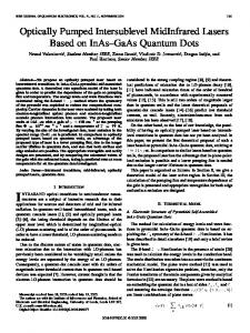
ation is slightly less at 500 MeV due to two depolarizing resonanceswhich are crossed during acceleration. This paper describes changes to this source which have resulted in a measured polarization increase to 78% (at 300 keV) and 75% (at 230 MeV) with 2.5 PA of protons extracted from the cyclotron. The optically pumped polarized ion source (OPPIS) is based on a proposal by Anderson [3]. A hydrogen plasma is created within an electron-cyclotron-resonance (ECR) cavity by 28 GHz microwave ionization in the axial magnetic field of a superconducting solenoid (see fig. 1). The typical absorbed microwave power is 850 W. Protons are extracted from the ECR cavity plasma and are directed, at approximately 2.5 keV, through a polarized rubidium vapour where a fraction of the protons are neutralized by picking up a polarized electron. The polarization is induced by optical pumping of the rubidium vapour with laser light tuned to the rubidium D, transition at 795 run. Most of the neutralized hydrogen is created in an excited atomic state and it is necessary to use the high magnetic field of a superconducting solenoid to preserve the polarization as the hydrogen atom decays to the ground state. An electrostatic deflector immediately downstream of the neutralizer removes all charged species from the beam which
NEUTRALIZER DEFLECTOR CELL PLATES
IONIZER CELL
-!-
RF WAVEGUIDE COUPLING \
SONA SHIELD
WINDOW CONDUCTING
I SmCo MAGNETS
IRON YOKE
D \ CRYOPUMP
Figure 1. A schematic of the TRIUMF optically pumped polarized He ion source.
121 Pump Lasers
Laser Relay Optics
300 kV
To Cyclotron Figure 3. Schematic diagram of the laser optical pumping arrangement have passed through the rubidium. The axial magnetic field reverses sign, between the neutralizer and a subsequent negative ionizer, in order to enhance the nuclear polarization through a Sona type transition. The sodium vapour of the ionizer produces an equilibrium fraction converting about 10% of the atomic hydrogen beam into an H- ion beam. This negative ion beam is accelerated to 300 keV and transported to the cyclotron through a 50 m long beam line which uses electrostatic focusing elements to preserve the polarization. II. DEVELOPMENTS A. Extraction Electrodes Several extraction electrode systems for the ECR ion source were investigated. The best results were obtained from a system of three electrodes, consisting of 1 mm thick molybdenum disks spaced 1 mm apart, with a 31 hole hexagonal array of 1 mm diameter holes. The electrodes are powered in an accel-accel mode. B. Neutralizer The rubidium neutralizer cell consists of three thermally isolated components; i.e., an entrance snout, a vapour canal and a rubidium reservoir which can be isolated by a valve. The canal and reservoir are independently heated. The rubidium thickness can be maintained reliably stable over periods of a week, with or without beam. While the optically pumped region of the canal is roughly 0.6 cm (FWHM) in diameter, the actual canal diameter is 2 cm in order to improve vacuum pumping of from the canal and thereby reduce the probability of proton neutralization with the unpolarized gas molecules. C. Ionizer The ionizer cell, which uses sodium vapour, is about 8 cm long. With a sodium thickness of typically 40 to 80*10’3 atom/cm2 in the ionizer, it is necessary to recirculate the sodium in order to achieve a reasonable operating period for
each sodium charge and to avoid frequent maintenance of the nearby electrostatic focusing elements. D. Lacer System Two modified SPECTRA-PHYSICS 3900-S2 TiS lasers are used to polarize the rubidium vapour. The divergent beams from the lasers are brought by a relay lens assembly into the ion source through the K beam line (see fig. 2). Each laser beam expands to approximately fill the central 0.6 cm (FWHM diameter) of the neutralizer canal. The laser frequency is in resonance with the Zeeman shifted D, absorption line in the neutralizer. The proton polarization is reversed by changing the helicity of the light and simultaneously changing the frequency (of both lasers) to account for the Zeeman shift. The stability of the TiS lasers, measured in terms of mode hopping between adjacent etalon modes , is an order of magnitude better than the high power dye lasers which were previously used with sodium. Compared to the system based on sodium, the photon flux in the neutralizing cell has been increased by a factor of two by converting to rubidium and TiS lasers. E. Polarimeter A nuclear polarimeter based on the low energy analyzing power of the 6Li(p,‘He)ct reaction has been developed [4]. The analyzing power for detecting 3He at 130’ is approximately 0.21 at 300 keV. With a current of 2 PA of K, 1% statistics are achieved in about 3 minutes. A second polarimeter based on selective quenching of the metastable 2S state of hydrogen [5] has been used for source polarization studies and to examine correlations between the ion beam current and its helicity.
III.
OPERATIONAL
EXPERIENCE
A. Source Characteristics The H- current from the source depends on a number of parameters such as the thicknesses of vapour in both the
122 ionizer and the neutralizer as well as the proton current drawn from the ECR plasma. There is an unpolarized component in the beam which originates from proton neutralization by hydrogen upstream of the charge deflection plates. This unpolarized background is nearly independent of the rubidium thickness and its relative contribution to the total H- becomes less as the rubidium neutralizer vapour thickness is increased. However, the polarization of the rubidium vapour drops as the thickness is increased, due to radiation trapping and to the limited number of photons from the lasers. As a result, there is an optimal rubidium thickness of 3 to S*lO” atoms/cm2 which gives the maximum proton polarization. The effective emittance of the H- beam leaving the source is primarily determined by the ionizer [6]. The total change in emittance in the transverse plane, as the beam passes through the ionizer, is given by, & = n?/2r,, where r, is the radius of the ion orbit in the peak magnetic field of the ionizer and r is the radius of the beam envelope which in this case is equal to the radius of the ionizer canal.
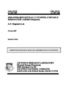
from the n = 2 orbit to the II = 1. The Sona transition has been optimized but is estimated to be only about 95 96efficient in transferring the spin from the electrons to the proton. Finally the ionizer magnetic field is decreasing at the sodium canal condensers, and since the nuclear polarization increases with field strength the polarization is reduced. Moreover some sodium escapes from the canal and gives rise to a lower polarization when it ionizes the hydrogen outside of the magnetic field. The net depolarization from all of these factors is estimated to be about 0.76f0.08 of the rubidium polarization.
C. Sfability A typical polarized proton user requests a few percent stability in the current and polarization over periods of weeks. At the source, this implies stability criteria to: a) the proton current from the ECRIS, b) the sodium neutralizer thickness, c) the sodium ionizer thickness, d) the laser power into the neutralizer, and e) the laser frequency. The proton current, from the ECRIS. remains remarkably stable for periods of 24 hours and then only requires small changes to the hydrogen B. Polarization The full polarization of the rubidium atoms is not flow and to the voltage on the second electrode; processes transferred to the proton due to a number of factors. The which require only a few minutes to complete and are transmeasured transfer efficiency is shown in fig. 3. The rubidium parent to the user. After the first few hours, to reach thermal vapour polarization varies spatially and is measured by a 1 equilibrium, the alkali-metal thicknesses in the neutralizer and mm diameter probe beam along the source axis, where the the ionizer remain stable without further adjustment for rubidium polarization is at its maximum. Polarization transfer periods of one week. Since most experiments require that the is also lost due to charge exchange on the unpolarized residual proton spin regularly be flipped, it is necessary to quickly gas (mainly hydrogen) in the rubidium vapour canal. Depo- restabilize the lasers after each spin flip. Spin flip rates are larization of the electron spin results from spin-orbital limited, at present, by the computer control system. The coupling in t.hehydrogen atom as the polarized electron jumps lasers are designed to permit a more rapid frequency switching, eventually up to 100 Hz. (The etalon has a measured mechanical response time of 1 ms.) I
b 2
I
V. REFERENCES [II
P P
100 s ; .% .N
I
I
Rb
L. Buchmann,
K. Jayamanna,
C.D.P.
Levy,
M. McDonald,
Ruegg, P.W. Zelenskii, “A
Schmor, A. dc Optically
Belov,
V.G.
Polushkin,
Nucl.
Ul
go
Inst.
Meth.,
A306,
Pumped, Polarized
pp. 413-425,
R.
A.N. He Source”,
1991.
P.W. Schmor, L. Buchmann, K. Jayamanna, C.D.P. Levy, M. McDonald, R. Ruegg, “Operational experience with the TRIUMF Optically Pumped Polarized He Ion Source”,
Conference Record of the 1991 IEEE Particle Accelerator
80 (31
Conference, Accelerator Science and Technology, vol. 3, pp. 1925-1927, 1991. L.W. Anderson, “Optically Pumped Electron Spin Polarized Targets for use in the Production of Polarized Nucl. Inst. Me&., 167, pp. 363-370, 1979.
70 141
60 0
I
I
I
I
2
4
6
8
Rb thickness
[lo”
atoms
[51
10
cm-‘]
Figure 3. Rubidium polarization and nuclear I-I- polanization at 300 keV as functions of rubidium thickness at a laser power of 8W.
L. Buchmann, “A Proton Polarimeter for Below 300 keV”, Nucl. Inst. Meth., A301,pp. A.N.
Z&en&ii,
S.A.
Beams”,
Beam Energies 383-388, 1991.
Kokhanovskii, V.M. Lobashev, V.G.
Polushkin, Ions”,
Ion
“A Laser Source of Polarized Protons Nucl. Inst. Meth., A245, pp. 223-229, 1986.
and
H-
161 W.M. Law, C.D.P. Levy, P.W. Schmor, J. Uegaki. “Emittance Growth due Exchange in a Solenoid”, 539, 1988.
to Hydrogen Nucl. Inst.
lonisation by Charge Meth., A263, pp. 537-