The Use of a Requirements Modeling Language for Industrial Applications
Brian Berenbach
Florian Schneider, Helmut Naughton
Corporate Research and Technology Siemens Corporation Princeton, USA
[email protected]
Chair for Applied Software Engineering Technische Universität München Munich, Germany {florian.schneider,helmut.naughton}@in.tum.de engineering, on the other hand, had no facilities to permit tracing to the existing UML model. Story 2 (Inability to connect goals, features, and requirements): On a project to define a common software platform, a large number of features were originally planned. To record the rationale for the features, sessions were held with management to define goals, and then map the goals to product features and their derived requirements. Management required that, on the one hand, the model would highlight which parts of the product were motivated by which goals and, on the other hand, would show which goals were realized in the product. Unfortunately, it was not possible to use goal models (expressed e.g. in i* [1] or KAOS [2]) within the same tool that the company already had (a standard UML modeling tool). A workaround for the problem was to overload UML constructs for use as goals and goal relationships. While this solved part of the problem of linking goal and use case models it was still not possible to express tradeoffs between goals in the tool. Moreover, while the platform was configurable, variation points could not be described because of missing feature modeling support (see problem 1 above). Story 3 (Inability to capture hazards and threats in a model during early requirements elicitation): On several projects, the issues of security and safety were raised during early elicitation (i.e. modeling) efforts. For example, if software is used during surgery, one potential hazard is the misidentification of the patient (e.g. operating on the wrong arm). Traditionally, hazard and threat modeling have been done after product requirements have been completed. However, it was found that for optimal risk mitigation, security and threat modeling needed to also occur during requirements elicitation as well as afterwards. Having separate processes and tools for standard modeldriven RE and hazard and threat modeling created an artificial barrier between the different efforts, and hindered seeing the “big picture”. Story 4 (Lack of clear delineation of customer processes and system use cases, and overloading of the rectangle): During the modeling of a mail sorting system for the U.S. Postal Service (USPS), a deficiency of the SysML was observed. That is, on the one hand the USPS processes, describing USPS operations in general, had to be modeled, and on the other hand the use cases associated with the use of new, proposed mail sorting equipment had to be modeled as
Abstract—During model-driven requirements elicitation sessions for several commercial products, weaknesses were identified with available modeling languages such as UML and SysML. Continued frustration when attempting to use the UML for requirements capture eventually resulted in collaboration between Siemens and Technische Universität München (TUM) to define a new visual requirements language called the Unified Requirements Modeling Language (URML). This paper describes some of the rationale behind the development of the URML, highlights some of the more unusual features of the language, and, finally, describes its use on a commercial project. Keywords-Modeling; modeling
I.
Graphical
models;
Requirements
INTRODUCTION
Siemens currently provides products and services in three major sectors – industry, healthcare, and energy. One author (Berenbach) has worked on products in all three sectors for several years, including such diverse products and services as medical software and equipment, gas turbines, mail sorting systems, and rail infrastructure. While working on defining product requirements in these different areas, the author found that both customer processes and product requirements were sufficiently complex to warrant modeling. During modeling sessions however problems were experienced with existing modeling languages and accompanying tools. These problems will be briefly described in the following four stories. Story 1 (Inability to connect products, product lines, features, and design models): During a requirements elicitation session with a Siemens energy company, the topic of product line support became an issue. The initial objective was to reverse the requirements from an existing product and then use that information to define the requirements for a more standardized product that could be quickly customized in the field, rather than the existing technique of handcrafting custom solutions. It became apparent though, that what the customer wanted was not a product, but a product line. The existing UML model could not be extended to model the product line aspect, as the UML is not able to express feature trees and has no notation to mark core assets. Not using the UML was not feasible, as it was the projects’ standard modeling language used to discover requirements. Existing tools for product line
c 2012 IEEE 978-1-4673-2784-8/12/$31.00
285
RE 2012, Chicago, Illinois, USA
well. The need to use similar or in some cases, the same symbols for the two modeling efforts resulted in considerable confusion when working with USPS experts. Because the symbols were the same, the experts frequently could not tell whether a process description was meant to describe current operations, or future ones resulting from the introduction of the system under development. Moreover, the overloading of the rectangle to represent several different kinds of objects (e.g. an object, a requirement, a test case, a block, a constraint, a class, a test case, etc.) tended to make readabilty of models by non-experts harder as diagrams would often have different types of objects with different semantics, all represented by rectangles. From the stories, the authors extracted core requirements that a requirements modeling language for systems and software engineering should support: Requirement 1: The language should allow the modeling of features, variants, products, and product lines. Requirement 2: The language should allow the modeling of business rationale, goals, and goal tradeoffs. Requirement 3: The language should allow the modeling of threats, hazards, and mitigations. Requirement 4: The language should permit a clear distinction between process and use case modeling. Requirement 5: The language should formalize connections between the concepts mentioned in requirements 1-4. Requirement 6: The language should adhere to the principle of semiotic clarity, i.e. for every concept that is instantiable on a diagram, exactly one notational element should be present [3]. The remainder of this paper discusses the authors’ efforts to create a “Unified Requirements Modeling Language” (URML) that addresses the requirements listed above. First it provides some background on requirements engineering in Siemens projects and the proposed meta-model. It then describes the piloting of the URML on a Siemens project. We conclude by summarizing the authors’ two-year and unfinished journey to find a “pure” visual language for requirements engineering. II.
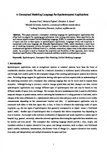
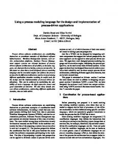
focuses on solutions in the customer environment (e.g. use cases), from which an inventory of needed features (including variations) and imposed constraints are derived. In addition to the created diagrams, a tabular representation of the requirements is used to create specifications from which test plans can be derived. As a result, modeling activities are synchronized with requirements capture, typically using commercial requirements databases integrated with commercial modeling tools. The need for doing hazard analysis derives from the fact that Siemens is working in some areas that are heavily regulated, e.g. concerning the creation of medical devices. That requires clearly documented processes. The U.S. Food and Drug Administration (FDA), for example, classifies software that may impact patient safety or security (e.g. a patient record) as a medical device [7]. Such a classification then mandates end-to-end traceability [8]. Similarly, the American Railway Engineering and Maintenance of Way Association (AREMA) prescribes concrete safety requirements for rail signaling systems. Companies competing for contracts in this area should be able to show how their systems address these safety requirements [9]. Such requirements mandate a complex tool chain because of the need for tracing across different tools, often in different global regions. Furthermore the need to distribute development makes the complex even more complex [10]. The following paragraphs provide some background on how we constructed the URML in order to address the requirements described in the introduction. The meta-model excerpts presented here to do not fully specify the language. They illustrate our approach to address the aforementioned requirements. To enhance the vividness of the diagrams, we used the URML graphical representation of the concept instead of using UML’s class box. To deal with requirement 1, we created a meta-model in which product lines are explicit (Fig. 1). As a product line is expressed using feature trees, we created a composite pattern for features and made ProductLine a subclass of the composite FeatureGroup. In addition, we added the concept of a Product, which consists of features and can be derived from a product line. A ProductSuite is a collection of related interacting products. For requirement 2, we created a stakeholder model that makes business stakeholders explicit and differentiates them from end-users and customers (Fig. 2). The concepts Goal, SoftGoal, and the relationships between goals are taken from goal-oriented approaches (e.g. Goal-oriented requirements languages (GRL) [11]) and as their semantics are not fundamentally different, they are not explained here any further.
BACKGROUND
Siemens leverages model-based requirements engineering (MBRE) as part of a typical requirements elicitation process. The benefits of requirements modeling are well known. For instance, Easterbrook et al. report that “the benefits gained from early modeling of unstable requirements more than outweigh the effort needed to maintain multiple representations” [4]. Barker states that “requirements models help design teams stay “on the same page” with each other” [5]. Nuseibeh and Easterbrook state that requirements modeling is a “fundamental activity in RE” [6]. From the experience taken from several projects we can state that modeling tends to make customer needs clearer. Moreover, the use of models enables stakeholders to systematically walk through customer processes, exposing customer needs and better understanding goal tradeoffs. Once customer operations are well understood, modeling
286
*
*
*
*
A b s tra c tF e a t ure
1
to introduce a common superclass Process. To allow hierarchical structure of processes, we applied the composite pattern.
exc lude s >
req uires >
-
core :bo olea n ma ndat ory :b oole an D a n g er
< con tains
-
Threat
*
«e nume ratio n» Fe ature Selec tionType IOR XO R AND
+ty pe 1
mi tigate s >
!
*
Fe ature Group
*
Y
0.. 1
Pro duct Line
*
*
-
un derCo nstru ction :boo lean
ha rms >
protects >
Ha rm e d E l e m e nt
+ty pe 1
*
XX Z
Mitig atio n
*
Fe ature
*
*
Hazard
*
A b s tra c tP roc e s s
< t rigge rs
pro babi lity severity
«e nume ratio n» HazardType
X
*
sei smica l me teoro logic al bio logic al che mica l rad iolog ical me chan ical ele ctrica l soc ial
*
Pro duct
Pro duct Suite
Figure 1. Feature modeling in the URML meta-model
ProceduralMitigation
RequirementMitigation
Figure 3. Excerpt from URML meta-model showing the concepts for danger modeling
We introduced the concept of an AssessmentSketch, which outlines how the realization of a goal can be tested (something which the GRL does not provide). This element can be used to capture suggestions for test cases during elicitation. *
!
A b s tra c tG oa l < expresses *
Softgoal
Goal *
*
Actor
* reports to >
Att ribute s S ta k e ho l de r - weight : int
Busines sSta keholder
Customer
ou tlines testc ase o f ^ *
0.0
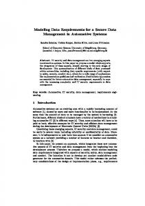
Figure 4. Visualization of different types of hazards
As sess mentSketc h
Figure 2. Excerpt from URML meta-model showing the concepts for goal and stakeholder modeling.
As the result of creating a formal relationship between the concepts danger, process, feature, and goal (requirement 5), Process is now a very central concept to our meta-model. It offers connections to danger, feature, and actor. Goals are linked to processes via the features realizing them (Fig. 6). As the meta-model excerpts presented here suggest, we achieved a high semiotic clarity (requirement 6) of the language by creating distinct symbols for each of the elements that URML users are able to put on a diagram.
For requirement 3, we distinguished between Hazards (physical harm - e.g. contusion) and Threats (immaterial harm - e.g. identity theft), with a common superclass Danger (Fig. 3). Dangers potentially harm assets, stakeholders, or service providers. They can be instantiated through a triggering process or because of a vulnerability of the process. Dangers are mitigated either by ProceduralMitigations (e.g. safety procedures manual) or RequirementMitigations (e.g. pressure sensor). For hazards, we designed a tentative classification of hazard types (Fig. 4). The delineation between business process and use case (requirement 4) was achieved by introducing a separate meta-class for each of the concepts (Fig. 5). We did see a strong commonality of the two concepts though and decided
287
can express the functions of the system and how the users of the system interact with it. SysML [17], which is a UML profile, adds an explicit construct for modeling requirements to the meta-model. Unfortunately the relationships introduced for requirements modeling stereotype UML’s Abstraction class. Thus any named element can be connected with these relationships.
A b s tra c tP roc e s s -
un derCo nstru ction :boo lean
*
< e xtend s *
*
IV.
P ro c e s s *
-
ato mic :bool ean po stCon dition :ch ar pre Cond ition :cha r
From the start of the project, the goal was to create a modeling language that would address the deficiencies described in the stories above. We therefore conducted a literature survey to find approaches that partially addressed one or more of these problems. Unfortunately we found no approach that comprehensively addressed the deficiencies. We extracted the main concepts from these approaches (most of them being modeling languages), interviewed domain experts (e.g. security analysis experts), and created a highlevel taxonomy. We found that the concepts we wanted to incorporate could roughly be partioned into the domains: danger modeling, feature and product line modeling, goal modeling, and process/requirements modeling. After consolidating the domains we created a meta-model. The meta-model was then iteratively reviewed and enhanced during multiple modeling sessions. Two art students created the graphical notation. While color would have been preferred, for practical reasons (e.g. the need to document on printers) we restricted symbols to black and white. Input regarding possible visualizations for the elements of the meta-model was queried from experts in two separate surveys with 21 and 11 respondents. Feedback on the understandability of the notational elements was gathered afterwards. For this purpose, two studies, one with 46 and one with 48 participants, were conducted. With the results of these studies, the icon-based visual notation of the URML was created. As a first prototype of the language, an add-in for the tool Enterprise Architect was developed on the basis of a UML profile. The URML reached a point where it could be piloted in July of 2011. It was used initially during elicitation sessions with Siemens technical staff to determine the value proposition for modeling medical equipment. The sessions were lightweight, spanning several days, and consisted initially of goal, product and process modeling, capturing hazards and proposed mitigations as we modeled. Once the URML model was created, the focus moved to design, and the SysML was used to model product design characteristics, with links back to relevant URML artifacts. Various structural and dynamic diagram types were used effectively to identify potential solutions for the requirements defined during the analysis sessions. As the model created in the aforementioned sessions is confidential, we are unable to present it here. Instead we present a sample model showing some elements of the URML in action (Fig. 7).
* Process Group
* < i nclud es
Busines sProcess
Us eCas e
Figure 5. Business process and use case are both describing parts of processes
III.
RESEARCH METHODOLOGY
RELATED WORK
We found few publications that holistically address the problems we are describing in this paper. All works presented here address more than one aspect of requirements engineering but do not take into account the full range of requirements we described before. None of the approaches specifically incorporates concepts that would facilitate hazard analysis or product line engineering. The concept of goal-orientation on the other hand is frequently described in the literature. Glinz envisions a “very lightweight modeling language” (VLML) [12], which is presented in some detail in a technical report of Glinz and Wüest [13]. The approach combines textual requirements with process concepts and goal models. While we do not know of a meta-model for the language at present, we think it will be interesting to compare it to the one of the URML in the future. Bleistein et al. present a framework for organizational IT [14] that combines goal models with Jackson context diagrams. On the basis of the framework, a method to derive low-level requirements from business strategy is presented. The User requirements notation (URN) [11] is a language standardized by ITU-T, the Telecommunication Standardization Sector of the International Telecommunication Union. It consists of two separate sublanguages, the Goal-oriented Requirements Language (GRL) and Use Case Maps (UCM). It clearly focuses on requirements engineering in early project phases [15] and allows modeling of goals and system usage. The meta-model of the UML solely supports requirements engineering through use cases and actors [16]. UML models
288
D a n g er -
pro babi lity severity
* -
*
P ro c e s s
A b s tra c tP roc e s s
< t rigge rs
-
un derCo nstru ction :boo lean
de tails >
ato mic :boo lean po stCon ditio n :ch ar pre Cond ition :cha r
*
rea lizes > *
Us eCas e
*
A b s tra c tG oa l
*
Fe ature
Figure 6. The URML meta-model formalizes the relationships between Danger, Use Case, Goal and Feature
pro tects int roduc e pressure sensor, new fun ction al req uirem ent that makes pressure sensor stop win dow mo veme nt
Wi ndow lift mo tor con trol shall int ercep t win dow mo veme nt wh en pressure sensor is trig gere d
uses Ch ild
mi tigate s
Wi ndow up bu tton
ha rms
Rising win dow cho kes c hild trig gers
con trols
Wi ndow lift mo tor con trol
de tails de tails Op en window
Wi ndow lift mo tor
de tails
expresses Pa rent
Ch ild sa fety
Pressure sensor
Ele ctric win dow lift
Figure 7. URML sample model
V.
Connecting processes and dangers was also found to be useful. Through the graphical presentation of the relationship of processes and related dangers, one participant was able to see why a certain sub-process was so error prone and remarked “This is the first time I am seeing this on one page”. In addition we were able to discuss whether some of the dangers that were mitigated by staff training could be mitigated technically (i.e. through a new system) in the future. The following issues that surfaced will require additional research with the URML: We had left out the control and information flow relationships between customer processes - a big oversight. It seems we were too much focused on the structural aspects of the model. It turned out that the behavioral aspect is sometimes needed to understand the source of dangers. Another problem was that we had not developed clear guidelines for the relationship between URML artifacts and standard SysML design artifacts. Consequently when adding designs to the model, there was some uncertainty as to which URML artifact to connect to a design artifact. Also, as the URML was implemented as a UML profile, some relationships inherited from the UML were unintentionally available to the modelers; that is,
RESULTS
The modeling sessions helped us evaluate the current state of the URML. This section will first describe the positive experiences and then go on describing some weaknesses of the current state of the new language. Being able to do goal and requirements modeling in the same tool was extremely valuable; without a goal modeling facility the rationale for many of the requirements would have been lost (See also van Lamsweerde [18] pp. 272-275). With the integration of goals, features, and requirements, it was possible to see the tradeoffs used later during the design sessions (e.g. product features vs. desired delivery date and cost of manufacture). Requirements diagrams had pointers to the design views (e.g. UML/SysML activity diagrams) in the same model, enabling instant “drill-down” from business rationale (goals) over product requirements and features, down to product design. By defining the product line and features in the same model as the requirements, it was easy to see the impact of variation points on detailed requirements and design; the product map appeared almost magically when switching to a matrix view.
289
performs in terms of scalability, usability, suitability and learnability.
modelers could draw relationships that had no clear semantics in terms of the URML. In summary, our preliminary qualitative analysis of the URML indicated that • Integration of goals, features, and requirements enables resolution of conflicts before implementation • Integration of product line, features, and requirements helps with impact analysis of product line variation points • Integration of processes and dangers helps with identification of error prone processes • The language should support control and information flow • Using an UML profile might not be the optimal way to enable tool support for a domain-specific modeling language VI.
REFERENCES [1]
[2] [3]
[4]
CONCLUSIONS
In this paper, we highlighted what we believe are key features needed in a visual language for the early elicitation of requirements. We provided information on how the unified requirements modeling language syntactically addresses these needed features. We then presented our first experience with the usage of the unified requirements modeling language in an industrial setting. Our main takeaway from the modeling sessions was that the facilities offered by the URML are really useful. We got positive resonance regarding the possibility of connecting goals, features, processes, and dangers - so far unconnected concepts - in an URML model. This does however not lead to the conclusion that the language is complete right now. This paper represents an impression taken from the first steps of evaluating the language. Further evaluations will show whether additional concepts need to be added and whether the meta-model of the language needs to be adjusted. Further evaluations which can be presented to the research community will however rely on us finding good and realistic example problems, that are not confidential.
[5]
VII. FUTURE WORK
[12]
[6]
[7] [8]
[9] [10]
[11]
As already mentioned, the URML is work in progress. There are some items on the roadmap we will start working on this year. One planned addition to the meta-model is the incorporation of innovation management concepts (e.g. ideas and suggestions). This would permit quickly referencing early innovations during construction of a system model. Another plan is the addition of a lightweight process modeling technique that allows to model the ordering of processes. In order to enhance the existing Enterprise Architect [19] add-in, we plan to create a rules engine that allows checking constraints on user models. How these constraints will be expressed and attached to the meta-model will be explored. Regarding the visual notation of the language, we intend to research visualization alternatives to the classic arrow notation for relationships. Future use of the language will undoubtedly highlight additional deficiencies. While extending the language as outlined above, we also intend to evaluate how the URML
[13] [14]
[15] [16] [17] [18] [19]
290
E. Yu, “Towards modelling and reasoning support for earlyphase requirements engineering,” presented at the Requirements Engineering, Proceedings of the Third IEEE International Symposium on, 1997, pp. 226–235. A. Dardenne, A. van Lamsweerde, and S. Fickas, “Goaldirected requirements acquisition,” Science of computer programming, vol. 20, no. 1, pp. 3–50, 1993. D. L. Moody, “The ‘Physics’ of Notations: Toward a Scientific Basis for Constructing Visual Notations in Software Engineering,” IEEE Transactions on Software Engineering, vol. 35, no. 6, pp. 756–779, 2009. S. Easterbrook, R. Lutz, R. Covington, J. Kelly, Y. Ampo, and D. Hamilton, “Experiences using lightweight formal methods for requirements modeling,” IEEE Transactions on Software Engineering, vol. 24, no. 1, pp. 4–14, 1998. D. Barker, “Requirements modeling technology: a vision for better, faster, and cheaper systems,” presented at the VHDL International Users Forum Fall Workshop, 2000. Proceedings, 2000, pp. 3–6. B. Nuseibeh and S. Easterbrook, “Requirements Engineering: A Roadmap,” presented at the Proceedings of the Conference on The Future of Software Engineering (ICSE '00), New York, New York, USA, 2000, pp. 35–46. J. F. Murray Jr, “CDRH Regulated Software: An Introduction.” Mar.-2010. General Principles of Software Validation; Final Guidance for Industry and FDA Staff, U.S. Department Of Health and Human Services - Food and Drug Administration - Center for Devices and Radiological Health - Center for Biologics Evaluation and Research, Jan. 2002. “Communication & Signals Manual of Recommended Practice,” American Railway Engineering and Maintenance of Way Asssociation (AREMA), 2007. M. Heindl and S. Biffl, “Risk management with enhanced tracing of requirements rationale in highly distributed projects,” presented at the GSD '06: Proceedings of the 2006 international workshop on Global software development for the practitioner, 2006. “User requirements notation (URN) -- Language definition,” International Telecommunication Union, 2008. M. Glinz, “Very Lightweight Requirements Modeling,” presented at the Requirements Engineering Conference (RE), 2010 18th IEEE International, 2010, pp. 385–386. M. Glinz and D. Wüest, “A Vision of an Ultralightweight Requirements Modeling Language,” no. July, 2010. “B-SCP: A requirements analysis framework for validating strategic alignment of organizational IT based on strategy, context, and process,” Information and Software Technology, vol. 48, no. 9, pp. 846–868, 2006. “User Requirements Notation (URN) -- Language requirements and framework,” International Telecommunication Union, 2003. “OMG Unified Modeling Language (OMG UML), Superstructure,” Object Management Group, formal/2010-0505, May 2010. “Systems Modeling Language (SysML), ver. 1.2,” Object Management Group, 2010. A. van Lamsweerde, Requirements Engineering - From System Goals to UML Models to Software Specifications. Wiley, 2009. Enterprise Architect. [Online]. Available: http://www.sparxsystems.com/products/ea/index.html. [Accessed: 04-Mar.-2012].