ALSO IN: Guiding systems for computer assisted surgery: introducing synergistic ... Under computer control, the synergistic device may allow the surgeon.
The Use of Localizers, Robots and Synergistic Devices in CAS
Jocelyne Troccaz* Michael Peshkin** Brian Davies*** Abstract There are many roles for electromechanical devices in image guided surgery. One is to help a surgeon accurately follow a preoperative plan. Devices for this purpose may be localizers, robots, or recently, synergistic systems in which surgeon and mechanism physically share control of the surgical tool. This paper discusses available technologies, and some emerging technologies, for guiding a surgical tool. Characteristics of each technology are discussed, and related to the needs which arise in surgical procedures. Three different approaches to synergistic systems, under study by the authors (PADyC, ACROBOT, and Cobots), are highlighted.
1 Introduction An electromechanical device of some sort is needed in image-guided surgery, in order to connect the "information world" of images, plans, and computers, to the physical world of surgeons, patients, and tools. That is the situation in which a surgical plan has been created based on diagnostic images, and it is the job of the surgical system to guide the surgeon in the accurate execution of his own preoperative plan. The surgeon is again in direct contact with the surgical tool, but an interface device must also be connected to that tool, so that the computer may in some way provide guidance. Thought of as human interfaces, the perceptual quality of such a device is often the most prominent factor in the performance of surgical systems. We appreciate a quality that is sometimes called transparency - the quality of being perceptually absent. One purpose of this paper to describe the measures of interface device performance which determine their suitability for use in various surgical situations. We give examples of surgical situations that particularly depend on one or another of these measures. Another purpose is to describe several classes of interface devices, with examples. Previous descriptions of such devices relied on a decomposition in passive, active and semi-active systems [1] in which the degree of passivity was often associated with a type of technology. We prefer to define a new classification based on function rather than mechanism including localizers, robots, and also a new class which we call synergistic devices. Synergistic devices are intended for direct physical guidance of a surgical tool which is also held and controlled directly by a surgeon. Each of the authors is pursuing a different approach to synergistic devices, and these approaches are outlined. The paper concludes with a discussion of the applicability of the technologies to various surgical purposes. ----------------* TIMC/IMAG Laboratory, Faculte de Medecine de Grenoble, Domaine de la Merci, 38706 La Tronche cedex – France ** Mechanical Engineering Dept., Northwestern University, Evanston IL 60208 – USA *** Mechatronics in Medicine Lab., Imperial College of London, London SW7 2BX – UK
SOURCE: The use of localizers, robots and synergistic devices in computer assisted surgery, Jocelyne Troccaz, Michael A. Peshkin, Brian Davies, CVRMed/MRCAS, Grenoble, March 1997 ALSO IN: Guiding systems for computer assisted surgery: introducing synergistic devices J. Troccaz, M. Peshkin, B. L. Davies, Medical Image Analysis 2 (2), 1998
2 Classes of interface devices 2.1 Localizers Localizers are devices that measure the coordinates of a tool or a pointer, but do not directly control that location. The location is controlled by the surgeon, by physically moving the tool or pointer, and is unconstrained by the localizer. Examples of localizers are passive arms with joint angle sensors, such as the Faro arm [2]. Optical tracking systems perform a similar function, simply collecting coordinates. Localizers have the advantage that achieving transparent behavior is easier than for devices with actuators. In other words they cooperate easily with a surgeon, interfering little with his intended motion. Lacking actuators, however, they cannot offer guidance to the surgeon by providing physical constraint. Instead, the surgeon must explicitly observe and obey some other less immediate mode of guidance, usually a video display of some sort. An interesting variation is the addition of brakes to the joints of an otherwise unpowered localizer arm. In this way, if a surgeon can be guided visually to position the arm in a desired location according to a preoperative plan, the device can "lock" in that position and can subsequently be used as a physical guide. However the intrinsic physical mode of the localizer is passive, allowing the surgeon full mobility. 2.2 Robots Most robots are fully actuated, having a motor driving each joint. Thus the position of the robot's end-effector is predominantly determined by how it runs its motors, and it intrinsically has little patience for physical "cooperation" with a surgeon. For some applications no cooperation is required; the robot works autonomously. An example is the Adler/Latombe radiosurgery system, in which a heavy payload is moved about a large workspace, both of which exceed human scale. No direct physical input from the surgeon is possible, or needed (see §4.2). In some circumstances, the robot needs some help from the operator, for instance for registration. In this case the "cooperation" problem can be addressed by adding a force sensor to the robot end-effector. The control computer is then aware of forces reflecting a surgeon's intended motion. It may direct the robot motors to comply with that intent. In practice it has so far been very difficult to achieve perceptually smooth cooperative motion in this way, but even primitive "force following" by the robot is useful (see §4.2). Another approach, however, leaves some of the joints of the robot unactuated but still equipped with sensors. Motion of these joints is naturally free and smooth. Since the decision to leave a joint unactuated is permanent, clever kinematic design of the robot is required so that the resulting "free" motions remain the appropriate ones even as the robot's configuration changes. An example of these mixed actuated/unactuated mechanisms is CMI's Aesop, which holds a laparoscope inserted through a trocar into the body (cf. §4.2). The intrinsic physical mode of actuated robots is active controlling position, and cooperating physically is not their natural mode.
2.3 Synergistic devices Part of our purpose in this paper is to introduce the notion of synergetic devices, in contrast to localizers and autonomous robots. Synergistic devices are intended for cooperative physical interaction with a surgeon. Both the surgeon and the synergistic device hold the tool, apply forces to it and to each other, and impart motions. Under computer control, the synergistic device may allow the surgeon to have control of motion within a particular plane, while the device dictates motion perpendicular to that plane, for instance. As an example, suppose the surgeon and the synergistic device cooperatively hold a bone saw. The surgeon may maneuver the saw at will within the defined plane, cutting at any desired speed from any angle of approach, and avoiding anatomic structures that must not be damaged. At the same time, the synergistic device confines the blade of the saw to a defined plane based on a preoperative plan, so that the eventual resected surface is flat and corresponds to the plan. Arbitrarily shaped surfaces,
with greater or fewer than two dimensions, can be defined based on preoperative plans, and enforced by the synergistic device. The surgeon is free to control the remaining degrees of freedom. Synergistic cooperation has the benefit that the robot can provide accurate, precise geometric motions whilst the surgeon holding the tool can feel the forces applied and modify them appropriately. It also has the psychological benefit that the surgeon is in direct control of the procedure. Several of us have realized the value of a synergistic control of motion. Several distinct approaches to achieving that goal will be described in §4.3.
3 Technical needs In the following we will use the term mechanism to refer to any of these three types of systems. The technical specifications of robotic guiding systems answer a triple requirement: the ability to assist the execution of a given clinical task by providing accurate and repeatable precise geometric motions with intricate paths and repetitive motions tirelessly; ease of use for a clinical operator; and with maximum safety for both the medical staff and the patient. In the following paragraph we will focus on user-oriented characteristics and safety-oriented characteristics only. Task-oriented characteristics are defined in the robotics literature (see [3] for instance). 3.1 Operator-oriented characteristics The transparency of the system characterizes how user-friendly is the displacement of the mechanism. This qualitative factor depends mostly on the kinematic architecture of the mechanism which may promote some directions of motion e.g. wrist rotations are generally much easier to move than, say, a "reach" extension. Quantitative dexterity measurements (manipulability, isotropy, ...) have been introduced in the robotic domain [4] to quantify the kinematic extent to which a manipulator can attain all velocities. For instance, when a mechanism is isotropic no direction of displacement is favoured. Transparency also depends on the mechanical architecture of the mechanism and how light and well-balanced it appears to the operator. A compromise is often required between rigid structures which can apply large forces over a wide region and the needs of sensitive, low inertia systems capable of high speed and accuracy. In the case of synergistic systems, the mechanism has to provide position and force information to make the operator feel the modelled data (anatomic obstacles for instance) and/or the task to be performed. Let us call them constraints. This results in several characteristics related to the type of constraints that can be provided by the mechanism. This is a design, control and modelling problem. As we will see further some systems give the feeling of rigid constraints whilst others feel deform able . In the former case, motions are completely forbidden in certain directions. In the latter case, they are only resisted. Deformable constraints may be plastic or elastic. A plastic deformable constraint could be useful to make the operator feel obstacles from a certain distance. An elastic constraint would make the mechanism move on its own if the operator releases the end-effector. In other words the elastic would react whilst the plastic only resists the motions of the operator. The shape of available constraints is also of importance: it corresponds to the type of objects and tasks that can be felt. For instance, tasks such as linear drilling trajectories, planar cuts or 3D osteotomies for prosthesis implantation should be available to the orthopaedic operator. More complex constraints could combine position and orientation constraints. For instance, the tool could be constrained to follow accurately a given trajectory with a given range of allowed orientations. Finally, one should know if constraints are programmable or not i.e. if they can be redefined for a new task or vary during the execution of one task. In addition to accuracy one should also characterize how smoothly the operator can move in free space or follow the border of the constraint. Frequency is an important factor linked to the interaction between the system and the operator. 200ms should be adequate to feel soft surfaces whilst lms would be necessary to feel a hard surface.
3.2 Safety-oriented characteristics Reducing the maximum speed of the joints may increase safety. Adding redundancy to the mechanism (mechanics, control, sensors) may also improve safety. However this can also have the effect of allowing a large envelope, within which the position could be uncertain in the event of a failure. Failure modes have to be carefully studied for all types of mechanisms. For instance, the position of mechanism should keep stable when power is removed. For synergistic systems, it is important to know if the constraints can be violated and under which force conditions they will. 4 Technologies 4.1 Localizers Mechanical localizers were introduced for endo-nasal surgery in the early eighties [5, 6] and for neurosurgery [7, 8]. They generally consist of man-powered mechanisms that have several degrees of freedom and encoders on each joint. The position and orientation of a tool attached to the end-effector of the mechanism is computed in real-time from the geometric model and the instantaneous values of the encoders. In small workspaces that are typical in surgery, an accuracy ranging from 0.1mm to lmnin can be achieved. However, constraints or large forces applied to the mechanism can deteriorate these values significantly. As compared to non mechanical navigators, these systems have the disadvantage of being cumbersome in the operative field. A major limitation is also that they can track only one object. However, they always give information, without any possibility of being obstructed, as can occur with the non-contact localizers. Another advantage is that they can be fixed in a definite position to hold an instrument (however, in some systems, the application of brakes can cause a small motion when they are operated). Such a mechanism has to be as light and balanced as possible to limit the efforts to be produced by the human operator especially when anthropomorphic mechanical architectures ("arms") are used. Therefore, the workspace and inertia have to be small and the "drag" on the various joints have to be similar. Transparency has to be as good as possible. This includes also a good visual interaction since all the topographic information given to the operator has to be rendered on displays. They must be as fast and ergonomic as possible. Because motions are generally man-powered, such mechanisms are intrinsically very safe. 4.2 Robots ROBODOC The Robodoc system has been developed for machining of femoral bones in hip surgery [9, 10]. Accurately machining the bone according to the shape of the prosthesis to be implanted allows perfect fit between the cavity and the implant and is intended to provide best bio-mechanical behaviour and long term stability of the implant. The robot is a SCARA based architecture which workspace has relatively limited interaction with the surgical field. In the Robodoc system, the robot control subsystem performs an extensive safety check and monitors cutting force to ensure that unnecessary force cannot harm the patient [11]. The RoboDoc system uses force following to allow the surgeon to guide the robot into proximity of the surgical site, after which the robot performs the surgery autonomously. Radiotherapy irradiation robot [12] developed a frameless system for neuroradiosurgery based on the use of an industrial six axes robot which carries the radiation device. The robot is rather big because it has to position very accurately a heavy payload. It has parallel elements in its structure to increase its rigidity. Its very large workspace intersects the patient area. This system allows position tracking of the patient head during irradiation. Tracking is allowed for small motions only to avoid potential collision with the environment. A spherical architecture would have certainly been more adapted to this kind of application. A number of watch dogs are used at the control level to increase safety.
AESOP The AESOP system from Computer Motion Inc. is dedicated to laparoscopic procedures [13]. It is used to move the laparoscope and is controlled by foot pedals operated by the surgeon from video images. Mounted onto the surgical table, this SCARA-based architecture has a very limited workspace and a task-dedicated design. Indeed, it has 6 dofs, 4 actuated joints and 2 passive joints. The passive joints (no 4 and 5) are designed such that the laparoscope can rotate freely about the pivot point constraint imposed by the patient's abominal wall therefore describing only conical motions. This provides the system with very interesting safety characteristics. 4.3 Synergistic systems Measures of perceptual quality for synergistic devices might focus on the question of transparency as described in section 2. In particular we may ask how unobtrusive the device can be when it wishes to allow the surgeon full control over position. We will call this its transparency in "free mode". Equally important is the smoothness with which the device can enforce a constraint surface. Optimally the surgeon would be able to use a software-defined constraint surface, as exhibited physically by a synergistic device, in much the same way that a surgeon normally uses a physical guide or jig. One wishes a guide to be smooth, preferably of low friction so that one may glide across it, and for it to be rigid and strong. We will refer to these characteristics as the smoothness of the device in "constraint mode". Mechanical guide At the border of this classification, we can find systems such as [14] for which a six axes actuated mechanism autonomously positions a mechanical guide in stereotactic neurosurgery. This guide is used by the surgeon to guide a linear tool according a pre-planned trajectory. In this case, the constraint is simple (a linear trajectory) and rigid. Moderated braking We mentioned above the possibility of superimposing brakes on the joints of a passive localizer arm. The surgeon thus has complete and free control of position, until a desired position is reached, at which point the localizes can be entirely "frozen" and subsequently used as a rigid guide. An extension of this idea, which approaches the function of a synergistic device, is to use brakes which can be fractionally activated rather than turned entirely on or off. One would hope that, with appropriate control of the brakes, such a device could constrain the motion of a surgical tool grasped jointly by the robot and the surgeon, and could for instance confine the surgeon's motion of the tool to with a region or on a plane. Such a device has in fact been explored in the CAS field by Taylor [15]. The transparency of such a device in its free mode can be excellent, since it reverts to being a passive localizer when the brakes are off, and thus can be moved very easily. Unfortunately it turns out that brakes are extremely difficult to control smoothly. It is very difficult using brakes to exhibit a constraint surface at all, except in the fortuitous instances when one joint can be fully locked and another left fully free. Passive Arm with Dynamic Constraints (PADyC) Exhibiting a smoothconstraint surface requires the establishment of allowed, non zero, velocities, such that the end-effector can move parallel to the constraint surface freely. Such a mechanism is the core of PADyC. In PADyC, each joint is velocity-limited by two reference clutch plates, which thereby define an angular-velocity "window". The joint may turn only at an angular velocity which falls between the limits established by the two reference clutch plates. The angular velocities of these two reference plates are controlled by a computer. When PADyC is in free mode, the angular velocity windows of all joints are set wide open, and the device allows unrestricted freedom of motion naturally. As a constraint surface is approached
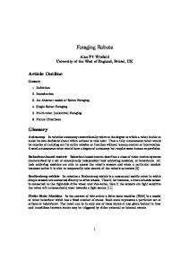
however, the angular velocity windows are made narrower in some directions, such that ultimately the only velocities available to each joint are the one which move the device away from or parallel to the constraint surface. Constraints include "free", "position", "trajectories" and "regions" modes [16]. Those are rigid and programmable constraints; nevertheless, some soft surface behaviours can be simulated by suitable velocity windowing. Because of its principle (no anticipation of next motion is made possible), PADyC natural modes are the free and region modes. The last one is particularly interesting for anatomic obstacle avoidance (neurosurgery or endonasal surgery for instance) and resection operations. The system is smooth and frictionless. A two link PADyC has been built (see figure 1.a), and a three-link version is under construction.
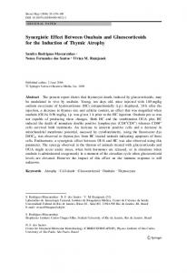
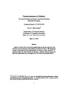
Fig. 1. (a) PADyC: A two degrees of freedom laboratory prototype. The operator moves the PAD-y CyC in the plane and the system constrains the motion according to pre-planned strategy. (Courtesy of Dr Jocelyne Troccaz, TIMC Laboratory) (b) Cobot: A two degrees of freedom prototype. The operator moves the cobot in the plane using the handle and the system automatically rotates the wheel in order to describe a given trajectory. (Courtesy of Dr Michael Peshkin, North Western University) (c) Close-up of ACROBOT mechanism and end-effector showing controlled degrees of freedom (Courtesy of Dr Brian Davies, Imperial College of London) Cobots Armlike cobots with revolute joints are more difficult to describe than translational cobots, and interested readers are referred to [17, 18]. Suffice it to say that the principle of operation is the same. Here in the interest of space we will describe the simplest possible translational cobot. As presented below it is a two degree of freedom device. Several higher degree of freedom cobots are under development, as well as an armlike cobot. The two degree of freedom translational cobot consists of a rolling wheel, free to roll on a flat working surface. A computer controlled motor steers the wheel, and a handle is attached to it as shown in figure 1.b. The user and the cobot interact through this handle, and the workspace of the cobot is the horizontal plane in which the user can move the handle. Note that the motor cannot make the handle move; only the user can do that. The motor only steers. It can however enforce a constraint surface, which in this example should be a understood as a constraint curve in the planar workspace. It can enforce this constraint simply by steering the wheel parallel to it. Because the rolling wheel can only be moved in the direction it is aimed at each moment, the user perceives an impenetrable boundary at the constraint surface. In practice this illusion is convincing. Since the constraint arises mechanically, it is smooth and frictionless. The intrinsic modes of PADyC are its free and region modes. In contrast, cobots have an intrinsic mode which is
the trajectory mode. Free and region modes must be achieved through computer control. To allow the user full freedom of motion, the control computer uses a force sensor to detect which direction the user wishes to move the handle. It then steers the rolling wheel to coincide with the desired direction, much the way that a caster wheel under the leg of a piece of furniture aligns itself with the desired direction. 1 he constraints are rigid and programmable.
ACROBOT As mentioned in section 4.3, a conventional robot may attempt. to cooperate with a human user by :measuring the user's applied force and driving Joint motors to comply with these forces. However the transparency is usually poor. AC ROBOT (or Active Constraint ROBOT) is a robot, specially designed for transparent cooperation with a human user, while nevertheless using actuated joints. ACROBOT uses backdrivable motors and transmissions, where conventional robots are usually made strong and stiff at the expense of backdrivability. Mechanically, ACROBOT places the human user and the robot's motor on a more nearly equal basis for controlling position. A conventional robot gives a great advantage to the robot's motors, as it is intended to be insensitive to externally applied forces. In "region"' mode ACROBOT's motors are actively driven to comply with the user's force. Good transparency can result due to mechanical sharing of forces between motor and human, made possible by backdrivability. As the user approaches and then contacts a constraint surface defined in the preoperative plan, the motors are actuated to gradually increases its resistance until, at the edge of the permitted region, it prevents further motion by the operator. Constraints may be deformable (elastic or plastic)) and rigid. Following preliminary trials of a prototype a new 4 axis robot, :mounted on passive structure, has been constructed and evaluated (see figure Lc) Whilst the ACROBOT is currently being used for knee surgery, the system is also suited to a range of orthopaedic and soft tissue procedures. 5 Discussion Synergistic devices are intended to cooperate physically with a surgeon. They must offer good transparency, but also be able to produce forces. These forces (based on a preoperative plan) can guide the surgeon physically, much in the way that a physical jig or guide offers guidance. In contrast to video guidance, direct physical guidance promises to be more efficient and accurate. Especially when the number of degrees of freedom (angles and positions) that the preoperative plan specifies is large, it becomes difficult and frustrating for a surgeon to follow video guidance. Three approaches to synergistic devices were described. In one, ACROBOT, a special purpose robot is used. It may bring speed and tracking properties that PADyC and Cobots cannot. We also described two other approaches to synergistic devices, both of which rely on novel joint mechanisms. Both of them are intrinsically safer than ACROBOT. PADyC's intrinsic modes are the "region" and "free" modes, whilst Cobots' intrinsic mode is the "trajectory" mode. ACROBOT has no preferred mode. It is debatable what will be the future of those CAS systems that perform surgery based on a preoperative plan. Is the computer's primary role to be to present the plan visually to the surgeon, and the surgeon works essentially freehand but with visual reference to the plan? If so, localizers offer the needed functionality with a minimum of interference to the surgeon's delicate work. Or perhaps CAS systems will increasingly execute surgical plans themselves, with the surgeon's direct touch becoming less and less important. If so, semi-autonomous robots with little opportunity for physical input from the surgeon may hold the future. Yet a third possibility, and the one to which the synergistic devices being developed by the authors is addressed, is that surgeon and computer will need to interact physically in a direct and cooperative and sensitive way. This is required if the surgeon is to remain responsible for some aspects of tool motion, while simultaneously the computer is responsible for others. Synergistic devices are designed for this intimate cooperation.
References 1. P. Cinquin and al. Computer Assisted Medical Interventions at TIMC Laboratory: passive and semi-active aids. IEEE Engineering in Medicine and Biology magazine, special issue Robots in Surgery, 14(3):254-263, 1995. 2. ISG Technologies. Viewing wand operator's guide. Technical report, ISG Technologies Inc., 1993. 3. Craig John J. Introduction to Robotics Alechanics and Control. Addison Wesley, 1986. 4. C. Klein and B. Blaho. Dexterity Measures for the Design and Control of Kinematically Redundant Manipulators. Int. J. Robotics Res., 6(2):72-83, Summer 1987. 5. R. Mosges, G. Schlondorff, L. Klimek, D. Meyer-Ebrecht, W. Krybus, and L. Adams. Computer assisted surgery. an innovative surgical technique in clin ical routine. In H.U. Lemke, editor, Computer Assisted Radiology, CAR 89, pages 413-415, Berlin, June 1989. Springer-Verlag. 6. L. Adams, W. Krybus, Meyer-Ebrecht D., R. Rueger, J.M. Gilsbach, R. Moesges, and G. Schloendorff. Computer assisted surgery. IEEE Computer Graphics and Applications, pages 43-51, May 1990. 7. Y. Kosugi, E. Watanabe, and J. Goto. An articulated neurosurgical navigation system using MRI and CT images. IEEE Transactions on Biomedical Engineering, 35(2):147-152, 1988. 8. H.F. Reinhardt. Neuronavigation : a ten years review. In R. Taylor, S. Lavallee, G. Burdea, and R. Mosges, editors, Computer-integrated surgery. MIT Press (Cam bridge, MA), 1995. 9. R.H. Taylor, H.A. Paul, B.D. Mittelstadt, E. Glassman, B.L. Musits, and W.L. Bargar. A robotic system for cementless total hip replacement surgery in dogs. In 2nd Workshop on Medical €4 Healthcare Robotics, pages 79-89, Newcastle, UK, 1989. D.T.I. 10. R.H. Taylor, H.A. Paul, C.B. Cutting, B. Mittelstadt, W. Hanson, P. Kazanzides, B. Musits, Y.Y. Kim, A. Kalvin, B. Haddad, D. Khoramabadi, and D. Larose. Augmentation of human precision in computer-integrated surgery. ITBAf (Innovation and Technology in Biology and Medicine) , Special Issue on Robotic Surgery, 13(4):450-468, July 1992. 11. Kazanzides P., Zuhars J., Mittlestadt B., and Taylor R.H. Force sensing and control for a surgical robot. In IEEE Conference on Robotics and Automation, pages 612-617, May 1992. 12. J. Adler, A. Schweikard, R. Tombropoulos, and J-C. Latombe. Image-guided robotic radiosurgery. In MRCAS 94, Medical Robotics and Computer Assisted Surgery, pages 291-297, Pittsburgh, PA, 1994. 13. Uecker D.R., Lee C., Wang Y.F., and Wang Y. A speech-directed multi-modal man-machine interface for robotically enhanced surgery. In 1st Symposium on Medical Robotics and Computer-Assisted Surgery, 1994. 14. J. Lavallee, S. Troccaz, L. Gaborit, P. Cinquin, A.L. Benabid, and D. Hoffmann. Image guided robot: a clinical application in stereotactic neurosurgery. In IEEE Int. Conf. on Robotics and Automation, pages 618-625, Nice , France, 1992.
15. R.H. Taylor, C.B. Cutting, Y.Y. Kim, A. Kalvin, D. Larose, B. Haddad, D. Khoramabadi, M. Noz, R. Olyha, M. Bruun, and D. Grimm. A model-based optimal planning and execution system with active sensing and passive manipulation for augmentation of human precision in computer-integrated surgery. In 2nd International Workshop on Experimental Robotics, Toulouse(France), June 1991. Springer Verlag. 16. Y. Delnondedieu J. Troccaz. Semi-active guiding systems in surgery. A two-dof prototype of the passive arm with dynamic constraints (PADyC). Mechatronics, 6(4):399-421, June 1996. 17. M.A. Peshkin J.E. Colgate and W. Wannasuphoprasit. Nonholonomic haptic displays. In IEEE International Conference on Robotics and Automation, 1996. 18. J.E. Colgate M. Peshkin and C. Moore. Passive robots and haptic displays based on nonholonomic elements. In IEEE International Conference on Robotics and Automation, 1996.