arXiv:astro-ph/9804175v1 17 Apr 1998. THE VERY SMALL ARRAY: STATUS REPORT. Michael E. JONES & P. F. SCOTT. Cavendish Laboratory, Madingley ...
arXiv:astro-ph/9804175v1 17 Apr 1998
THE VERY SMALL ARRAY: STATUS REPORT Michael E. JONES & P. F. SCOTT Cavendish Laboratory, Madingley Road, Cambridge CB3 0HE, UK.
We are contructing an interferometric telescope, the Very Small Array, to study the cosmic microwave background on angular scales 0.2–4.5◦ . The physical layout and electronic design of the telescope are optimised to give maximum protection from systematic effects, while still providing sufficient sensitivity to make high signal-to-noise images. A prototype single baseline is currently being tested, with scientific results expected during 2000.
1
Introduction
It is widely accepted that the majority of the cosmological results that might be obtained from the cosmic microwave background (CMB) will come from accurate measurements of the CMB power spectrum over the region of the accoustic peaks, that is in the range 100 < l < 2000 (where l is the spherical harmonic multipole). We have therefore been constructing an instrument, the Very Small Array (VSA), to measure the power spectrum (and provide images) in precisely this angular range. We have argued previously1 that interferometers are very well suited for ground-based CMB measurements, given their relative immunity to the atmosphere and other systematic effects compared with switched-beam experiments. Here we will describe some of the more detailed design considerations of the array, and review the progress of the project so far. 2
The VSA—vital statistics
The VSA will consist of an array of 14 antennas, operating in the 26–36 GHz band. The size of the antennas is determined by the largest angular scale we wish to observe: l = 100 corresponds to an angular scale of 3◦ .6, or an interferometer baseline of 16 wavelengths. Our antennas have a clear aperture of 143 mm, ie about 15 wavelengths in the centre of the band. The number of antennas is fixed simply by the cost and complexity of the whole telescope— the more simultaneous baselines present, the better. In order to measure the smallest angular
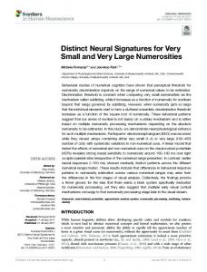
Figure 1: Sketch of VSA layout showing both large and small antennas, and the two extreme positions of the tip-table.
scales (l = 2000 corresponds to a baseline of 320λ) without compromising the fraction of the synthesised aperture that is filled, we will also use alternative antennas about 2.25 time larger. Using the best available front-end amplifiers (a design kindly supplied by NRAO), an observing bandwidth of 1.5 GHz (limited by bandwidth smearing), and a site with good transparency and stability at 30 GHz (Teide Observatory, Tenerife), we should obtain maps with 7 µK sensitivity per 30′ (12′ ) pixel over a 4◦ .5 (2◦ ) field in 300 hours observation, using the smaller (larger) antennas. 3 3.1
Design considerations Tracking arrangement
One of the main advantages of interferometers is fringe rotation. That is, because the rotation of the earth constantly changes the relative path from the source to each antenna, the complex visibility due to the source is phase modulated at a rate that depends on the baseline vector and the direction to the source. Synchronous detection at this frequency results in all spurious signals, due to eg crosstalk, atmospheric emission, or bright sources in far sidelobes, being attenuated by factors which can be very large (easily 25 dB). However, this is only true if the antennas are mounted so that the relative path does change, e.g. if the antennas are fixed to the ground and track individually. A conflicting requirement is that the antennas be very closely packed. The sensitivity of a synthesised aperture is degraded compared to a single aperture with the same beam by the fraction of the aperture that is filled. For an array of N antennas of size d, aperture efficiency η and maximum baseline D, this factor is roughly f = ηN (D/d)2 . It is much easier to pack antennas very closely if they do not move relative to each other. We therefore need a design in which the antennas can be packed closely in two dimensions, yet have a large change of relative path as they track. They must also, of course, have excellent sidelobe performance (the Sun is about 90 dB more powerful than the final noise level) and be free from crosstalk. The design we have selected (Fig. 1) achieves these goals by using the the conical hornreflector antenna (CHRA) design2 already used successfully on the Cosmic Anisotropy Telescope3 , with a modified mounting arrangement. The antennas are mounted on a table, with the horn
Switch waveform 1 Switch waveform
A A +
Antennas AB
Antennas
B
Bandpass filter
Synchronous detection
Synchronous detection B
2 2 (A+B) - (A-B) = 4AB
Bandpass filters
Switch waveform 2
Figure 2: (Left) Simple multiplying interferometer. (Right) Plus-minus correlator as used in the VSA. This is insensitive gain fluctuations in either input.
axis in a vertical N-S plane. Tracking in the E-W direction is obtained by rotating the mirror about the optic axis of the horn; in the N-S direction, by tipping the table about a horizontal E-W axis. Restricting the E-W tracking range of the mirror to ±35◦ allows E-W packing of the antennas as close as 1.3 aperture diameters. The antennas are mounted on the table with the horn axis at 35◦ to the table top; this allows arbitrarily close packing of the antennas in the N-S direction. Tipping the table by up to 70◦ achieves a zenith angle coverage of ±35◦ in the N-S direction. Most of the tracking motion is individual to the antennas, with only a small motion of the table (none when observing at the celestial equator). This results in a fringe rate almost as high as for a fully individually-mounted array. The antennas themselves have sidelobe levels of better than −50 dB at angles > 30◦ from the main beam, thanks to careful control of the boundary conditions (using corrugations) at the edges of the diffracting aperture. When combined with the shadowing effect of the table and interferometer effects (fringe rotation and bandwidth smearing) this should allow daytime operation for all but very close directions to the Sun. 3.2
Correlator design
The correlator has to be free from systematics, and insensitive to influences such as receiver gain instability. A digital corelator is out of the question, given the bandwidth required (> 1 GHz). A simple analogue multiplier, such as a double-balanced mixer, is sensitive to gain fluctuations in either input. The design we are using, which was also used in the CAT, is based on Ryle’s phase-switching correlator4 . In Ryle’s original design, the signal from one antenna has a 180◦ phase switch inserted, and the signals from the two antennas are then added. The power of the sum signal is then detected, and the component at the phase-switch freqency amplified. After integration, only a term proportional to the product of the two signals remains, and it is relatively insensitive to gain variations in either side. In the VSA correlator (Fig. 2), both the sum and difference are squared, and their difference taken, before detection at the switch frequency. This directly removes fluctuations in the total power of each antenna, providing a further protection against low-frequency noise due to the receivers or the atmosphere. This correlator design has excellent performance, but is expensive and bulky, especially given that we further protect against systematics by housing each correlator unit in a separate earthed box. This means that we can only afford to build one frequency channel. However, we need to observe at more than one frequency in order to separate the CMB signal from the Galactic signal. In making such spectral-index observations, it is a great advantage to have well-matched aperture-plane coverage at each frequency. By observing sequentially at each frequency, we can
Mirror Horn (hidden) Drive motor Cryostat
He refrigerator
Figure 3: Two prototype VSA antennas under test.
re-scale the array each time to provide identical aperture-plane coverage. This would not be possible with simultaneous observation in widely-spaced observing bands. 4
Project status
The project was given funding in July 1996, and at the time of writing (March 1998), two complete antennas, with all their associated backend and correlator, have been built and are being tested (Fig. 3). Assembly of the complete telescope (in Cambridge) will proceed during 1998, and it is hoped to ship the array to Tenerife during 1999, with science observations beginning shortly thereafter. Acknowledgments The VSA is a collaborative project between the Cavendish Laboratory (Cambridge University), the Nuffield Radio Astronomy Laboratories (Manchester University), and the Instituto de Astrofisica de Canarias; many people at all three institutions are responsible for the work described here. The VSA is funded by the Particle Physics and Astronomy Research Council. References 1. Jones M.E., in Microwave Background Anisotropies, ed. Bouchet F.R., Gispert R., Guideroni B., Tran Thanh Van J., (Editions Fronteires, 1997). 2. Yassin G., Robson M. Duffet-Smith P.J., IEEE Trans. Antenn. Prop. 41, 357 (1993). 3. Robson M., Yassin G., Woan G., Wilson D.M.A., Scott P.F., Lasenby A.N., Kenderdine S., Duffet-Smith P.J., A&A 277, 314 (1993) 4. Ryle M., Proc. Roy. Soc. A. 211, 351 (1952)