Software development processes for component-based de- velopment (CBD) are well-defined and well-understood, to the extent that there is a widely accepted ...
The W Model for Component-based Software Development Kung-Kiu Lau, Faris M. Taweel and Cuong M. Tran School of Computer Science, The University of Manchester, Oxford Road, Manchester M13 9PL, United Kingdom {kung-kiu,ftaweel,ctran}@cs.man.ac.uk
II. CBD P ROCESSES
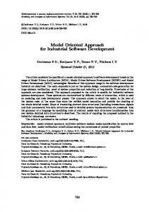
The CBD process in Fig. 1 does not explicitly address V&V, i.e. Verification and Validation. For general (modular) system development, the standard model for V&V is the V Model The V Model is an adaptation of the traditional waterfall model for modular system development. It defines a sequential process consisting of phases for requirements, system specification, system or architectural design, module design, implementation and V&V testing. ImplementaAcceptance System Acceptance testing tion consists of codrequirements test plan ing for the individual System System System specification test plan testing modules, and codArchitectural Integration Integration design test plan testing ing for integrating Module Unit Unit the modules into the design test plan testing entire system using Coding the architectural deFig. 2. The V Model. sign for the system. Testing follows coding. [25] (Fig. 2). Thus the coding phase elo
v De
t
en
pm
A number of development processes for CBD have been proposed, e.g. [4], [14], [21], [2], [7], to name but a few. (A recent survey can be found in [13].) Naturally these processes all reflect the desiderata of CBD [1], and converge on the general view depicted in Fig. 1.
III. T HE V M ODEL
g
Software development processes for component-based development (CBD) are well-defined and well-understood, to the extent that there is a widely accepted standard generic CBD process, namely one with separate processes for component development and (component-based) system development. However, the current standard CBD process does not yet take into account V&V (verification and validation) properly. Thus, compared to non-CBD processes for V&V, such as the more or less standard V Model in industry (in particular the avionics domain), the current standard CBD process needs enhancements for the purpose of V&V. In this paper we introduce a new CBD process that we call the W Model. This is related to the V Model; basically the W Model defines one V for the component development process, and one V for the system development process, and conjoins the two processes into a single CBD process. The V for component development defines a process for identifying and defining repository components from the domain requirements, i.e. from the domain model of the application domain, as well as V&V for such components. The V for system development defines a process for assembling or composing repository components (more precisely their instances) into a system according to the system requirements, as well as V&V for each component composition, and V&V for the resulting system.
sti n
I. I NTRODUCTION
The generic CBD process Requirements Analysis in Fig. 1 comprises Design two separate processes: Implementation Component Selection one for component Component Adaptation development, and one for Component Assembly component-based system Testing development. Component Maintenance development is also known as ‘development for reuse’, Component Component−based since it is concerned with Development System Development developing components Fig. 1. CBD processes. that can be stored in a repository and (re)used to build different systems. Componentbased system development is also known as ‘development with reuse’, since it is concerned with developing systems by reusing pre-built components (the result of the component development process). Each process follows the same life cycle of ‘requirements analysis, design, implementation, testing and maintenance’. For component development, implementation is a single activity, whereas for system development, implementation is a sequence of activities based on pre-built components, namely component selection, adaptation and assembly.
The research leading to these results has received funding from the ARTEMIS Joint Undertaking under grant agreement no. 100016 and from the Technology Strategy Board, UK. It has been carried out on the CESAR project (http://www.cesarproject.eu).
Te
Abstract—For general (modular) system development with verification and validation (V&V), the V Model is the industrial standard. For component-based development, there is a wellunderstood standard process, but it does not specifically address V&V. In this paper, we propose such a model, that we call the W Model. We have implemented it using Model-Driven Engineering.
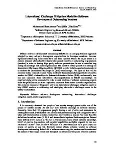
V&V An adaptation of the V Model Acceptance System Acceptance testing requirements test plan for CBD that System System System does incorporate specification test plan testing the bottomArchitectural Integration Integration design test plan testing up nature of Component Component Component CBD is that of design test plan testing [6]. It does so Coding by containing Fig. 3. Adapting the V Model for CBD. separate life cycles for component development and system development, like in Fig. 1. However, this adaptation really applies the V Model only to its system life cycle; there is no evidence of the V Model in its component life cycle (which is the same as the one in Fig. 1). In our view, to adapt the V Model properly for CBD, we need not only to incorporate both the component life cycle and the system life cycle, but also to apply the V Model to both of these cycles. In addition we need to specify a component model that defines the components (and their composition) properly. (A definition and survey of component models can be found in [18].) We have defined such an adaptation, using a component model that we have defined ourselves. Now we describe our adaptation, which we call the W Model. De
divides the whole process into ‘development’, the left arm of the V, and ‘testing’, the right arm of the V. During each of the development phases (in the left arm of the V), a test plan is drawn up for the corresponding testing activity (in the right arm of the V). For example, an acceptance test plan is drawn up from the requirements, since acceptance testing will be performed against the requirements. Similarly, unit test plans are generated from module design, since unit testing will be carried out on the modules, and so on. Testing follows a sequential process, in reverse order of the development phases, as is usual for modular system development. Thus unit testing is performed first, followed by integration testing, system testing and finally acceptance testing. Each testing activity is carried out according to the test plan generated during the corresponding development phase. The key property of the V Model is that it is a top-down approach to system design and development, as Fig. 2 clearly shows. First, a top-level design is made of the architecture of the entire system; this identifies and specifies sub-systems or modules, and their inter-relationships. Then the individual modules are designed according to their specifications in the top-level design. In general, this top-down approach may be applied successively, each time decomposing sub-systems or modules in the current level of design into further sub-systems or modules. This decomposition is repeated as many times as is necessary, until a final design is arrived at in which the design of the system as well as all the individual modules is deemed complete, i.e. no further decomposition is necessary or desirable.
nt
Te
me
sti
ng
lop ve
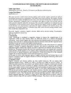
V. T HE W M ODEL Our component model [17], [15], [26] is called X-MAN, and we have defined a CBD process based on X-MAN. This process is shown in Fig. 4.
IV. A DAPTING THE V M ODEL FOR CBD Compared to the standard CBD process in Fig. 1, which contains two life cycles, one for component development and one for system development, the V Model contains only one life cycle, for system development. So, the question is ‘How can we adapt the V Model for V&V in CBD?’ The standard CBD process in Fig. 1 shows CBD as an essentially bottom-up approach to system design, in the sense that components have to be developed first (in the component life cycle), and any particular system is constructed from these components (in the system life cycle). In contrast, as we have explained in the previous section, the V Model (Fig. 2) is essentially a top-down approach to system design: the system is designed first (thus identifying the requisite components), and then components are developed. A straightforward adaptation of the V Model for CBD would be to retain the top-down approach to system design but use a component as a module, as shown in Fig. 3. For example, the V model adopted by the avionics industry as a CBD process (e.g. Airbus processes [9], [11]) is such an adaptation. However, such a straightforward adaptation of the V Model is at variance with the standard CBD process in Fig. 1, precisely because it does not include a component life cycle and consequently does not incorporate the bottom-up nature of CBD.
Component Life Cycle (for a domain) Domain knowledge
System Life Cycle (for one system) System requirements
Component Design Design and implementation of domain−specific components & connectors
System specification
Repository Component Deployment Deployment of components in a specific system
Fig. 4.
Component selection & adaptation System Assembly Composition of deployed components Architecture
X-MAN CBD process.
It consists of a component life cycle and a system life cycle, in line with the standard CBD process (Fig. 1). However, it differs slightly from the latter, in that its component life cycle is a more complete one, namely the idealised one [18]. The idealised component life cycle is so-called because it meets all the desiderata of CBD that have been identified in the literature [1]. It consists of two phases: component design and component deployment, and is set in the context of a problem domain. In the design phase, components are (identified and) designed and constructed according to the domain requirements or knowledge [16], and deposited into a repository. Repository components are domain-specific but not system-specific. In the deployment phase, components are retrieved from the repository and instantiated into executable 2
component instances which are then deployed into a specific system under construction. The system life cycle also differs slightly from that in Fig. 1 in that system design is now replaced by a completely bottomup process of component selection (from the repository) and adaptation, followed by (component deployment in the component life cycle followed by) system assembly, which is simply the composition of the deployed components. The bottomup nature of this process is indicated by an iterative loop in Fig. 4. It is worth noting that within this loop, the component life cycle links up with the system life cycle, since deployed components (from the component life cycle) are iteratively assembled into the system under construction (in the system life cycle). This link is denoted by the arrows between the two life cycles in Fig. 4, via the step of component selection and adaptation, and the step of component deployment. Applying the V Model to both the component and system life cycles yields a CBD process with V&V as shown in Fig. 5. Compared to the straightforward adaptation of the V Model Component Life Cycle (for a domain) Domain knowledge
System Life Cycle (for one system) System requirements
Component Design Design and implementation of domain−specific components & connectors
System specification
Component V&V
Repository Component Deployment Deployment of components in a specific system
Fig. 5.
VI. A M ODEL -D RIVEN I MPLEMENTATION We have implemented the W Model in a CBD tool following the Model-Driven Engineering approach. The implementation of the X-MAN Tool is done using the GME toolkit [12]. In GME, meta-models that contain definitions of elements, structures and syntax have to be defined first using UML-like class diagram notation. Models can then be created by instantiating the pre-defined meta-models. To provide behaviours for models, GME allows us to develop interpreters that can interact with models, i.e. execute or manipulate models. To implement the W Model, we have to implement: (i) the X-MAN component model, for defining and constructing components and their composition mechanisms; (ii) the component life cycle in the W Model; (iii) the system life cycle in the W Model; (iv) the link between the component and system life cycles; (v) component V&V; (vi) compositional V&V; and (vii) system V&V. For lack of space, we cannot describe these. The X-MAN component model has been described in other papers, e.g. [17], [15], [26]. Fig. 7 shows a Component Designer that supports the component life cycle: component design, V&V, and storage. It shows a component Locker under construction, with a design palette on the left, tree view of the design on the right, and the main design view in the middle.
Component selection & adaptation System Assembly Composition of Compositional deployed components V&V Architecture
System V&V
X-MAN CBD process with V&V.
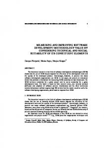
in Fig. 3, component V&V (which corresponds to component testing in Fig. 3) now occurs in the component life cycle, whilst compositional V&V (which corresponds to integration testing in Fig. 3) and system V&V (which corresponds to system testing in Fig. 3) occur in the system life cycle. The X-MAN CBD process with V&V in Fig. 5 can be re-cast straightforwardly as a process with two conjoined V Models, one for the component life cycle and one for the system lifecycle. These two V Models are conjoined via the step of component selection, adaptation, and deployment. This ‘double V’ process is shown in Fig. 6. We call it the W Model. (For one system in the domain) System requirements
Acceptance testing
System specification Domain knowledge Component design
Fig. 7.
System V&V
Component selection, adaptation & deployment Component V&V, certification Coding
System assembly
VII. D ISCUSSION AND C ONCLUSION
Compositional V&V
The name W Model has been used in software testing [22] and product line engineering [19] in the context of traditional (i.e. non-CBD) software engineering. [22] extends the V Model by adding a branch that integrates testing with debugging and code changes. [19] applies the V Model to
Coding
Fig. 6.
Component Designer: Component life cycle.
Fig. 8 shows a System Assembler that supports the system life cycle: composition of selected deployed component instances. Components are selected from the repository and instantiated, and the instances are then deployed. Similar to the Component Designer, the System Assembler offers design palette, tree view and main view for system design. In Fig.8 the system is being built from component instances CLLVoter, ClsSen11, etc., using connectors CLLSen Seq1, CLLSen Seq2 and so on.
The W Model.
We have highlighted the V&V activities in the W Model by boxes with black borders. 3
R EFERENCES
Fig. 8.
[1] M. Broy, A. Deimel, J. Henn, K. Koskimies, F. Plasil, G. Pomberger, W. Pree, M. Stal, and C. Szyperski. What characterizes a software component? Software – Concepts and Tools, 19(1):49–56, 1998. [2] L.F. Capretz. Y: A new component-based software lifecycle model. Journal of Computer Science, 1(1):76–82, 2005. [3] The SoftIntegration Ch SDK. http://www.softintegration.com/products/ sdk/chsdk/. [4] B. Christiansson, L. Jakobsson, and I. Crnkovic. CBD process. In I. Crnkovic and M. Larsson, editors, Building Reliable ComponentBased Software Systems, pages 89–113. Artech House, 2002. [5] E. Clarke, D. Kroening, and F. Lerda. A tool for checking ANSI-C programs. In Proc. of TACAS, 2004. [6] I. Crnkovic, M. Chaudron, and S. Larsson. Component-based development process and component lifecycle. Journal of Computing and Information Technology, 13(4):321–327, November 2005. [7] I. Crnkovic, M. Chaudron, and S. Larsson. Component-based development process and component lifecycle. In Proc. Int. Conf. on Software Engineering Advances, pages 44–53, 2006. [8] Firebird – The RDBMS that’s going where you’re going. http://www. firebirdsql.org/. [9] M. Fortes da Cruz and P. Raistrick. AMBERS: Improving Requirements Specification Through Assertive Models and SCADE/DOORS Integration. In F. Redmill and T. Anderson, editors, The Safety of Systems, Proc. 15th Safety-critical Systems Symposium, pages 217–241, Bristol, UK, February 2007. Springer London. [10] The Eclipse Foundation. Eclipse Process Framework Project (EPF). http://www.eclipse.org/epf/general/description.php. [11] A.P. Gaufillet and B.S. Gabel. Avionic software development with TOPCASED SAM. In Proc. Embedded Real Time Software and Systems 2010, 2010. [12] GME: Generic Modeling Environment. http://www.isis.vanderbilt.edu/ Projects/gme/. [13] K. Kaur and H. Singh. Candidate process models for component based software development. Journal of Software Engineering, 4(1):16–29, 2010. [14] G. Kotonya, I. Sommerville, and S. Hall. Towards a classification model for component-based software engineering research. In Proc. 29th EUROMICRO Conference, pages 43–52. IEEE Computer Society, 2003. [15] K.-K. Lau, M. Ornaghi, and Z. Wang. A software component model and its preliminary formalisation. In F.S. de Boer et al., editor, Proc. 4th Int. Symp. on Formal Methods for Components and Objects, LNCS 4111, pages 1–21. Springer-Verlag, 2006. [16] K.-K. Lau and F.M. Taweel. Domain-specific software component models. In G. Lewis, I. Poernomo, and C. Hofmeister, editors, Proc. 12th Int. Symp. on Component-based Software Engineering, LNCS 5582, pages 19–35. Springer-Verlag, 2009. [17] K.-K. Lau, P. Velasco Elizondo, and Z. Wang. Exogenous connectors for software components. In G.T. Heineman et al., editor, Proc. 8th Int. Symp. on Component-based Software Engineering, LNCS 3489, pages 90–106. Springer-Verlag, 2005. [18] K.-K. Lau and Z. Wang. Software component models. IEEE Trans. on Software Engineering, 33(10):709–724, October 2007. [19] J.-H. Li, Q. Li, and J. Li. The W-Model for testing software product lines. In International Symposium on Computer Science and Computational Technology, pages 690 –693, 2008. [20] ATESST PROJECT. East ADL2 Specification. http://www.atesst.org/ home/liblocal/docs/EAST-ADL-2.0-Specification 2008-02-29.pdf. [21] I. Sommerville. Software Engineering. Addison Wesley, 7th edition, June 2004. [22] A. Spillner. The W-MODEL – strengthening the bond between development and test. In Int. Conf. on Software Testing, Analysis and Review, 2002. http://www.sqe.com/stareast. [23] SQLAPI++ - C++ library for accessing SQL databases. http://www. sqlapi.com/. [24] D. Steinberg, F. Budinsky, M. Paternostro, and E. Merks. EMF: Eclipse Modeling Framework. Addison-Wesley, Boston, MA, 2. edition, 2009. [25] The V-model. Development standard for IT-systems of the Federal Republic of Germany, IABG. http://www.v-modell.iabg.de. [26] P. Velasco Elizondo and K.-K. Lau. A catalogue of component connectors to support development with reuse. The Journal of Systems and Software, 83:1165–1178, 2010.
System Assembler: System life cycle.
domain engineering and application engineering in product lines. This is similar to our approach, except that they do not use components and component composition, or the idealised component life cycle. In the context of CBD, our W Model is similar to standard CBD processes, e.g. [4], [14], [21], [7], in that they both contain separate life cycles for components and systems. However, unlike these processes, its component life cycle is the idealised one, which meets all the CBD desiderata in the literature [1]. In particular the idealised component life cycle defines component composition in both component design and component deployment phases. This emphasis on composition results in compositionality, which is an important property that is beneficial for practical system development, since it enables hierarchical system development and compositional reasoning. The component life cycle of our W Model is similar to that in the Y Model [2]. In the Y Model, components are developed using domain engineering techniques, and then archived. A framework is then defined for selecting components from the archive, and for assembling them into systems. The archive is of course just a repository. The framework is a structure for assembling components, and is therefore like a system assembler. However, the Y Model does not apply the V Model in any way to its component life cycle. (The same is true of component models that incorporate domain engineering techniques, e.g. EAST-ADL [20].) Moreover, the Y Model does not define a component model. For the purpose of V&V, our W Model is different from other adaptations of CBD processes based on the V Model for modular system design. The W Model contains a V model for both component and system life cycles, whereas other adaptations, e.g. [6], contain only a V model for the system life cycle. The value of a V Model for the component life cycle is that we can do component V&V and store pre-verified components in the repository. These components could be certified according to certain standards. Then, compositional V&V of composites can be carried out by re-using component V&V. 4