THEORETICAL END-DEPTH-DISCHARGE RELATIONSHIP FOR FREE OVERFALL By Vito Ferro1 ABSTRACT: Despite the many theoretical and experimental studies carried out in channels having different cross-section shape, slope, and roughness, the problem of the free overfall as a flow measuring device has not been completely solved, and other experiments are needed. A theoretically based end-depth-discharge relationship is obtained for both subcritical and supercritical flow in rectangular, triangular, and trapezoidal channels. For each cross-section shape, discharges predicted using the theoretical relationship are compared with the available experimental data.
INTRODUCTION The problem of the free overfall as a discharge measuring device has attracted considerable interest for almost 50 years, and a large number of theoretical and experimental studies have been carried out (Rouse 1936; Fathy and Shaarawi 1954; Delleur et al. 1956; Paderi 1956, 1959; Diskin 1961; Smith 1962; Rajaratnam and Muralidhar 1964a,b, 1970; Markland 1965; Bauer and Graf 1971; Ali and Sykes 1972; Neogy 1972; Kraijenhoff and Dommerholt 1977; Gill 1979; Hager 1983; Keller and Fong 1989; Terzidis and Anastasiadou-Partheniou (1990); Ferro 1992; Gupta et al. 1993; Marchi 1993; Anastasiadou-Partheniou and Hatzigiannakis 1995). The aforementioned investigations concerning the end-depth ratio (EDR), i.e., the ratio between the brink water depth ye and an upstream flow depth y1 [Fig. 1(b)], examined common shapes of the channel cross section (rectangular, trapezoidal, triangular, circular, parabolic) with different channel roughnesses and generally were restricted to subcritical flow. The analysis of these studies concluded that the EDR depends on the flow conditions (plane, three-dimensional) and the channel shape affecting the pressure distribution in the brink section, and on approach channel slope and roughness. Delleur et al. (1956), assuming a two-dimensional flow, theoretically obtained EDR values applying the momentum equation between the end section E-E and an upstream section 11, in which the pressure distribution may be taken as hydrostatic. For evaluating the pressure force at the end section, they introduced a pressure coefficient Cs , depending on the actual pressure distribution (if the pressure distribution is hydrostatic Cs = 1). The agreement between the experimental EDR values, measured both in a smooth flume and in a rough one, and the theoretical ones is obtained by choosing a suitable Cs value. In particular, the EDR measurements of Delleur et al. (1956) allow one to establish that the pressure distribution at the end section of a rectangular channel deviates more and more from the hydrostatic for increasing values of the ratio between the slope s and its critical values sc (Cs value decreases from 0.6 to 0.3 for flow ranging from subcritical to supercritical). Rajaratnam and Muralidhar (1964a,b) experimentally showed, for different shapes of the channel cross section, that for a subcritical flow the EDR is quasi-constant, whereas for a supercritical flow EDR rapidly decreases for increasing s/sc values. 1 Prof., PhD, Departimento di Ingegneria e Tecnologie Agro-Forestali, Sezione Idaulica, Facolta di Agraria, Universita di Palermo, Viale delle Scienze, 90128 Palermo, Italy. E-mail:
[email protected] Note. Discussion open until July 1, 1999. To extend the closing date one month, a written request must be filed with the ASCE Manager of Journals. The manuscript for this technical note was submitted for review and possible publication on May 20, 1997. This technical note is part of the Journal of Irrigation and Drainage Engineering, Vol. 125, No. 1, January/February, 1999. 䉷ASCE, ISSN 0733-9437/99/0001-0040 – 0044/ $8.00 ⫹ $.50 per page. Technical Note No. 15814.
The theoretical analysis and the measurements carried out for supercritical upstream conditions are less common in literature. Markland (1965) and Hager (1983) extended their theoretical analysis to supercritical flow in rectangular channels, whereas Rouse (1936) and Ali and Sykes (1972) carried out measurements in rectangular channels for the Froude number of the approach channel flow greater than 1. In these studies, the EDR is clearly related to the Froude number F1 calculated in the upstream cross section 1-1 in which the streamlines are parallel and thus the pressure distribution nearly hydrostatic. For a rectangular cross section, Ali and Sykes (1972) showed that the free vortex theory, the relaxation method (Markland 1965), and the momentum equation give similar ye /y1 ratio for F1 values greater than 3. In the Ali and Sykes’ paper, figure 4 also shows that the three theoretical relationships generally lie below the experimental points of Rouse (1936) and Ali and Sykes (1972). Other little known measurements, carried out by Paderi (1961), are available for a rectangular cross section. Diskin (1961) carried out measurements for a supercritical flow in a trapezoidal flume. In this paper, a theoretical analysis based on Terzidis’ results (Anastasiadou-Partheniou and Hatzigiannakis 1995) yields a general end-depth-discharge (EDD) relationship for both subcritical and supercritical flow in rectangular, triangular, and trapezoidal channels. For each cross section shape, discharges predicted using the theoretical relationship are compared with the available experimental data.
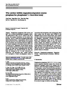
FIG. 1.
Scheme of: (a) Sharp-Crested Weir; (b) Free Overfall
40 / JOURNAL OF IRRIGATION AND DRAINAGE ENGINEERING / JANUARY/FEBRUARY 1999
THEORETICAL EDD RELATIONSHIP FOR RECTANGULAR CROSS SECTION The flow over an overfall in a rectangular channel can be assumed to be similar to the flow over a sharp-crested weir of the same section with a weir crest w = 0 and head above crest weir h = y1 [Fig. 1(a)] (Rouse 1949; Anastasiadou-Partheniou and Hatzigiannakis 1995). The flow velocity at the brink section is calculated by applying the energy equation on a streamline between section 1-1 and the end section E-E. In accordance with the theoretical procedure applied to compute the discharge over a sharp-crested weir, a zero pressure distribution and parallel streamlines at the brink, neglecting the contraction of the nappe, are initially assumed. Then, the discharge Q is computed by the following continuity equation:
冕
y1
Q=
2B兹2g Cc[H3/2 ⫺ (H ⫺ y1)3/2] 3 (1)
Cc兹2g(H ⫺ z)1/2B dz =
0
where g = acceleration due to gravity; H = y1 ⫹ V 21/2g denotes the energy head at section 1-1; z = vertical coordinate measured from reference level; B = section width in which Cc = contraction coefficient, equal to the ratio between the crosssection area Ae of the end section and the one A1 of the 1-1 section (Anastasiadou-Partheniou and Hatzigiannakis 1995) is introduced for taking into account the convergence of the streamlines. Introducing Cc = Bye /By1 into (1) and rearranging we obtain Q 2B兹2g ye [H 3/2 ⫺ (H ⫺ y1)3/2] 1/2 3/2 = Bg y 1 3Bg1/2y 3/2 y1 1
(2)
Introducing F1 = Q/Bg1/2y 3/2 into (2) we obtain 1 2兹2 ye F1 = 3 y1
冋冉 冊 冉 冊 册 3/2
H y1
⫺
H ⫺1 y1
3/2
(3)
Finally, taking into account that H F 21 ⫺1= y1 2
FIG. 3. (9)
Comparison between Experimental (Q /B, ye) Pairs and
Fe = F1
冋
册
(2 ⫹ F 21)3/2 ⫺ F 31 3F1
3/2
(7)
Fig. 2 shows, for the experimental data of Rouse (1943), Paderi (1961), and Ali and Sykes (1972), the good agreement between the experimental pairs (F1, Fe) and (7). Using the Froude number Fe definition and (7), the following theoretical EDD relationship is obtained Q = FeBg1/2y 3/2 = F1 e
冋
册
(2 ⫹ F 21)3/2 ⫺ F 31 3F1
3/2
Bg1/2y 3/2 e
(8)
For a subcritical flow (F1 = 1), (8) gives Q = 1.6542Bg1/2y e3/2
(9)
Fig. 3 shows a good agreement between the experimental (Q/ B, ye) pairs of Paderi (1954), Gill (1979), and Ferro (1992) and (9). The specific energy equation can also be applied for steady flow between the two sections, 1-1 and E-E, and taking into account in this derivation the end-pressure distribution factor Cs the following equation is obtained: y1 ⫹
(4)
V 21 V 2e = Cs ye ⫹ 2g 2g
(10)
from (3) we obtain the following relationship (5) for evaluating the ratio ye /y1
in which V1 = mean flow velocity in cross section 1-1; and Ve = mean flow velocity in the cross section E-E. Rearranging (10) we obtain the following equation:
ye 3F1 = y1 [(2 ⫹ F 21)3/2 ⫺ F 31]
ye 2 ⫹ F 21 = y1 2Cs ⫹ F 2e
(5)
Eq. (5) for F1 = 1 gives the classical result of Rouse ye /y1 = 0.715. Applying the continuity equation between section 1-1 and the end section E-E, the following equation is obtained:
冉冊 y1 ye
3
=
F F
2 e 2 1
(6)
Replacing (6) into (5) we obtain
Comparing (5) and (11) we obtain Fe =
冋
(11)
册
(2 ⫹ F 21)5/2 ⫺ F 51 ⫺ 2F 31 ⫺ 2Cs 3F1
1/2
(12)
For the given Cs value, (12) can be used to calculate for each F1 value the corresponding Froude number in cross section EE, whereas for each experimental couple (F1, Fe), (12) can be also used to determine the corresponding end-pressure distribution factor. Replacing (7) into (12) and rearranging, the following relationship for calculating Cs is obtained (2 ⫹ F 21)5/2 ⫺ F 51 ⫺ 2F 31 F 21 Cs = ⫺ 6F1 2
冋
册
(2 ⫹ F 21)3/2 ⫺ F 31 3F1
3
(13)
For a subcritical flow (F1 ⫺ 1), (13) gives Cs = 0.730. THEORETICAL EDD RELATIONSHIP FOR TRIANGULAR CROSS SECTION FIG. 2. (7)
Comparison between Experimental (F1, Fe) Pairs and
Assuming the flow over an overfall in a triangular channel to be similar to the flow over a sharp-crested weir of the same
JOURNAL OF IRRIGATION AND DRAINAGE ENGINEERING / JANUARY/FEBRUARY 1999 / 41
section (Fig. 1), the discharge Q can be computed by the following continuity equation:
冕 再
y1
Q=
2mCc兹2g(H ⫺ z)1/2z dz = 2mCc兹2g
0
冎
2y1 4 ⭈ ⫺ (H ⫺ y1)3/2 ⫺ [(H ⫺ y1)5/2 ⫺ H5/2] 3 15
(14)
in which m = side slope (m horizontal to 1 vertical). 2 2 Dividing (14) for mg1/2y 5/2 1 , introducing Cc = my e /my 1 = ( ye /y1)2 and rearranging, we obtain the following relationship for evaluating the EDR: ye = y1
F 1/2 1
冋
3 1
册
5 1
(15)
1/2
2F 2F 2 ⫺ ⫺ ⫹ (2 ⫹ F 12)5/2 3 15 15
Applying the continuity equation between section 1-1 and the end section E-E, the following equation is obtained:
冉冊 y1 ye
5/2
=
Fe F1
(16)
Replacing (16) into (15) we obtain
冋
册
5/4
2F 31 2F 51 2 ⫺ ⫺ ⫹ (2 ⫹ F 12)5/2 3 15 15
Fe =
(17)
F 11/4
Eq. (17) for a subcritical flow (F1 = 1) gives Fe = 1.3594. Comparing (15) and (11) we obtain Cs =
2 ⫹ F 21 2F 1/2 1
冋
册
2F 31 2F 51 2 ⫺ ⫺ ⫹ (2 ⫹ F 21)5/2 3 15 15
1/2
⫺
F 2e 2
(18)
Eqs. (18) and (17) for F1 = 1 give Cs = 0.772. Using the Froude number definition Fe and (17) the following theoretical EDD relationship is obtained: Q = Femg1/2y 5/2 e
冋
册
2F 13 2F 15 2 ⫺ ⫺ ⫹ (2 ⫹ F 12)5/2 3 15 15
=
F 1/4 1
5/4
mg1/2y e5/2
(19)
For verifying the applicability of (19) the experimental data of Peruginelli (1980) and Ferreri and Ferro (1990) were used. The measurements of Peruginelli were carried out by a sheetzinc flume having an s longitudinal slope ranging from 0 to 0.005 and an m side slope equal to 0.45. Ferreri and Ferro (1990) used a wood horizontal flume with m = 0.824. Fig. 4 shows a good agreement between the experimental (Q/mg1/2, ye) pairs and (19).
FIG. 5. Comparison between Experimental (ye /B, Q /B 5/2g1/2) Pairs and (22) for Subcritical Flow
THEORETICAL EDD RELATIONSHIP FOR TRAPEZOIDAL CROSS SECTION To avoid complex analytical solutions that make difficult the practical applications, the EDD relationship for a trapezoidal section can be obtained by (8) and (19). In particular, for each ye value the discharge Q of the trapezoidal cross section, having a bottom width B and a side slope m, is assumed to be equal to the sum of the discharge QR corresponding to the rectangle of width B and the discharge QT of the triangle with a side slope m. Assuming this hypothesis, the EDD relationships (8) and (19) can be rewritten as follows:
FIG. 4. Comparison between Experimental (Q /mg1/2, ye) Pairs and (19)
QR = F1 B5/2g1/2
冋
册 冉冊
(2 ⫹ F 21)3/2 ⫺ F 31 3F1
42 / JOURNAL OF IRRIGATION AND DRAINAGE ENGINEERING / JANUARY/FEBRUARY 1999
3/2
ye B
3/2
= R
冉冊 ye B
3/2
(20)
FIG. 6. Comparison between Experimental (ye /B, Q /B 5/2g1/2) Pairs and (22) for Supercritical Flow
QT = B5/2g1/2 = T m
冋
册
2F 31 2F 51 2 ⫺ ⫺ ⫹ (2 ⫹ F 12)5/2 3 15 15 F 11/4
冉冊 ye B
5/4
冉冊 ye B
m
5/2
5/2
(21)
in which R, T = discharge coefficient for the rectangular and triangular cross section, respectively. Therefore the EDD relationship for the trapezoidal cross section has the following equation: Q = R B 5/2g1/2
冉冊
3/2
ye B
⫹ mT
冉冊
5/2
ye B
(22)
It has to be noticed that the simple mathematical form of (22) obviously reduces (8) (for m = 0 or T = 0) and (19) (for R = 0) as particular cases. For verifying the applicability of (22) for subcritical flow the experimental data of Diskin (1961), Rajaratnam and Muralidhar (1970), Keller and Fong (1989), and Pagliara and Viti (1995) were used. Fig. 5 shows, for the subcritical case, a good agreement between the available measurements and (22). For supercritical flow, Fig. 6 shows the comparison between the experimental (Q/B5/2g1/2, ye /B) pairs of Diskin (1961) and (22). For supercritical flows, the dependence of the discharge coefficients R and T on F1 seemingly complicates the application of the EDD relationship because the Froude number F1, should be calculated by y1. Since upstream of the drop the channel flow is uniform, F1 can be calculated by the following equation: F1 =
s1/2R 12/3 ng1/2y 11/2
(23)
in which s = channel slope; n = Manning’s coefficient; and R1 = hydraulic radius of the channel cross section corresponding to the water depth y1. The water depth y1 has to be computed by (22), which can be rewritten as follows: A1
s1/2R 2/3 1 = B5/2g1/2 n
冋 冉冊 R
ye B
3/2
⫹ mT
冉冊册 ye B
5/2
(24)
which, taking into account (23), can be solved with respect to y1 for each measured ye value. CONCLUSIONS Despite the many theoretical and experimental studies carried out in channels having different cross-section shape, slope, and roughness, the problem of using the free overfall as flow measuring device has not been completely solved. The review of the literature studies establishes that the EDR depends on flow conditions (plane, three-dimensional) and channel shape affecting the pressure distribution in brink section, on approach channel slope and roughness.
The analysis carried out in the present paper is based on the recent results of Anastasiadou-Partheniou and Hatzigiannakis (1995) coupled with the use of the well-known flow specific energy equation. The EDD relationship was theoretically deduced for both subcritical and supercritical flow in rectangular, triangular, and trapezoidal channels. In particular, the EDD relationship of the trapezoidal cross section has a simple mathematical shape [(22)] deduced by the single EDD relationships of the rectangular (8) and triangular (19) cross sections. The simple mathematical form of (22) allows us to obtain (8) (for m = 0 or T = 0) and (19) (for R = 0) as particular cases. Taking into account the attainable measurement accuracy, the simplicity of the measurement device, its limitated cost, and its construction facility, the free overfall can be considered a useful flow measuring device. To improve the applicability of the free overfall in field research other experimental measurements are needed. For example, further research would be carried out for measuring the end pressure distribution and to calculate the corresponding Cs coefficient, for collecting data for supercritical flow in triangular and trapezoidal channels, and for testing the effect of roughness on the end depth. ACKNOWLEDGMENTS The research was supported by a grant from Ministero Universita` e Ricerca Scientifica e Tecnologica, Governo Italiano, and from Consiglio Nazionale delle Ricerche.
APPENDIX I.
REFERENCES
Ali, K. H. M., and Sykes, A. (1972). ‘‘Free-vortex theory applied to free overfall.’’ J. Hydr. Engrg., ASCE, 98(5), 973 – 979. Anastasiadou-Partheniou, L., and Hatzigiannakis, E. (1995). ‘‘General end-depth-discharge relationship at free overfall in trapezoidal channel.’’ J. Irrig. Drain. Engrg., ASCE, 121(2), 143 – 151. Bauer, S. W., and Graf, W. H. (1971). ‘‘Free overfall as flow measuring device.’’ J. Irrig. Drain. Engrg., ASCE, 97(1), 75 – 83. Delleur, J. W., Dooge, J. C., and Gent, K. W. (1956). ‘‘Influence of slope and roughness on the overfall.’’ J. Hydr. Engrg., ASCE, 82(4), 103830 – 1038-35. Diskin, M. H. (1961). ‘‘End depth at a drop in trapezoidal channels.’’ J. Hydr. Div., ASCE, 87(4), 911 – 932. Fathy, A., and Shaarawi, M. A. (1954). ‘‘Hydraulics of the free overfall.’’ Proc. ASCE, 80, No. 564, New York. Ferreri, G. B., and Ferro, V. (1990). ‘‘Efflusso non guidato di una corrente lenta da un salto di fondo in canali a sezione rettangolare.’’ Proc., XII Convegno di Idraulica e Costruzioni Idrauliche, Cosenza, 195 – 213 (in Italian). Ferro, V. (1992). ‘‘Flow measurement with rectangular free overfall.’’ J. Irrig. Drain. Engrg., ASCE, 118(6), 956 – 964. Gill, M. A. (1979). ‘‘Hydraulics of rectangular vertical drop structures.’’ J. Hydr. Res., 17(4), 289 – 302. Gupta, R. D., Jamil, M., and Mohsin, M. (1993). ‘‘Discharge prediction in smooth trapezoidal free overfall — (positive, zero, and negative slopes).’’ J. Irrig. Drain. Engrg., ASCE, 119(2), 215 – 224. Hager, W. H. (1983). ‘‘Hydraulics of plane free overfall.’’ J. Hydr. Engrg., ASCE, 109(12), 1683 – 1697. Keller, R. J., and Fong, S. S. (1989). ‘‘Flow measurements with trapezoidal free overfall.’’ J. Irrig. Drain. Engrg., ASCE, 115(1), 125 – 136. Kraijenhoff, D. A., and Dommerholt, A. (1977). ‘‘Brink depth method in rectangular channel.’’ J. Irrig. Drain. Engrg., ASCE, 103(2), 171 – 177. Marchi, E. (1993). ‘‘On the free overfall.’’ J. Hydr. Res., 31(6), 777 – 790. Markland, E. (1965). ‘‘Calculation of flow at free overfall by relaxation method.’’ Proc., Inst. of Civ. Engrg., 31, May, 71 – 78. Neogy, B. N. (1972). ‘‘Brink depth for trapezoidal broad crest weir.’’ J. Hydr. Engrg., ASCE, 98(12), 2171 – 2189. Paderi, F. (1954). ‘‘Sulla chiamata di sbocco (Notizie preliminari su rilevamenti per canali a fondo orizzontale.’’ L’Energia Elettrica, 10, 742 – 748 (in Italian). Paderi, F. (1956). ‘‘Sulla chiamata di sbocco in canale a fondo declive.’’ L’Energia Elettrica, 8, 792 – 800 (in Italian). Paderi, F. (1959). ‘‘Sulla chiamata di sbocco in canale a fondo acclive.’’ L’Energia Elettrica, 10, 883 – 888 (in Italian). Paderi, F. (1961). ‘‘Correnti in arrivo veloci in zona terminale di canale
JOURNAL OF IRRIGATION AND DRAINAGE ENGINEERING / JANUARY/FEBRUARY 1999 / 43
a forte pendenza prossima alla critica.’’ L’Energia Elettrica, 10, 874 – 881 (in Italian). Pagliara, S., and Viti, C. (1995). ‘‘Discussion of ‘Discharge prediction in smooth trapezoidal free overfall — (positive, zero, and negative slopes),’ by R. D. Gupta, M. Jamil, and M. Mohsin.’’ J. Irrig. Drain. Engrg., ASCE 121(1), 128 – 130. Peruginelli, A. (1980). ‘‘Chiamata di sbocco in sezione triangolare.’’ Idrotecnica, 6(2), 63 – 72 (in Italian). Rajaratnam, N., and Muralidhar, D. (1964a). ‘‘End depth for circular channels.’’ J. Irrig. Drain. Div., ASCE, 90(2), 90 – 119. Rajaratnam, N., and Muralidhar, D. (1964b). ‘‘End depth for exponential channels.’’ J. Irrig. Drain. Div., ASCE, 90(1), 17 – 39. Rajaratnam, N., and Muralidhar, D. (1970). ‘‘The trapezoidal free overfall.’’ J. Hydr. Res., 8(4), 419 – 447. Rouse, H. (1936). ‘‘Discharge characteristic of the free overfall.’’ Civ. Engrg., ASCE, 6(4), 257 – 260. Rouse, H. (1943). ‘‘Discussion of ‘Energy loss at the base of the free overfall,’ by W. L. Moore.’’ Trans. ASCE, 108, Paper No. 2204, 1383 – 1387. Rouse, H. (1949). Engineering hydraulics. Wiley, New York. Smith, C. D. (1962). ‘‘Brink depth for a circular channel.’’ J. Hydr. Engrg., ASCE, 89(6), 125 – 134. Terzidis, G., and Anastasiadou-Partheniou, L. (1990). ‘‘Discussion of ‘Flow measurement with trapezoidal free overfall,’ by R. J. Keller and S. S. Fong.’’ J. Irrig. and Drain. Engrg., ASCE, 116(6), 860 – 862.
APPENDIX II.
NOTATION
The following symbols are used in this paper: Ae A1 B Cc Cs Fe F1 g h H Q s sc ye y1 w z R T
= = = = = = = = = = = = = = = = = = =
cross-section area of end section; cross-section area of 1-1 section; section width; contraction coefficient; pressure coefficient; Froude number in end section; Froude number in first upstream cross section 1-1; acceleration due to gravity; head above crest weir; energy head at cross section 1-1; discharge; slope; critical slope; end water depth; upstream flow depth; height or weir crest above bed; vertical coordinate measured from reference level; discharge coefficient for rectangular cross section; and discharge coefficient for triangular cross section.
44 / JOURNAL OF IRRIGATION AND DRAINAGE ENGINEERING / JANUARY/FEBRUARY 1999