Hamid Reza Seyf Islamic Azad University, Karaj Branch, P.O. Box 31375-1746, Karaj, Tehran 3158777878, Iran e-mail:
[email protected]
Shahabeddin Keshavarz Mohammadian Islamic Azad University, Takestan Branch, Takestan, Qazvin 3158777878, Iran
Thermal and Hydraulic Performance of Counterflow Microchannel Heat Exchangers With and Without Nanofluids This paper analyzes the thermal and hydraulic performance of a counterflow microchannel heat exchanger (CFMCHE) with and without nanofluid as working fluid. A 3D conjugate heat transfer simulation is carried out using a finite volume approach to evaluate the effects of inlet Reynolds number, Brownian motion, and volume fraction of nanoparticles on the pumping power, effectiveness, and performance index of CFMCHE. The accuracy of the code has been verified by comparing the results with those available in the literature. A single phase approach is used for the nanofluid modeling. The base fluid used in the analyses as a basis for comparison was pure water. Two types of nanofluids, namely, water-Al2O3 with a mean diameter of 47 nm and water-CuO with a mean diameter of 29 nm, each one with three different volume fractions, are utilized. In addition, two temperature dependent models for the thermal conductivity and viscosity of nanofluids that account for the fundamental role of Brownian motion are used. Calculated results demonstrate that the effectiveness and performance index of CFMCHE decrease with increasing Reynolds number. Moreover, it is observed that the relative enhancements in the pumping power become more prominent for higher values of Reynolds numbers. It was also found that the performance index and pumping power are not sensitive to volume fraction at higher and lower Reynolds numbers, respectively. 关DOI: 10.1115/1.4003553兴 Keywords: numerical simulation, nanofluid, Brownian motion, effectiveness, thermal performance
1
Introduction
Multilayered microchannel heat exchangers 共MLMCHEs兲 are an important class of heat transfer devices used in bioengineering, microelectromechanical systems 共MEMS兲, aerospace, automotive industries, cooling of electronic components, etc. They were formulated several years ago and were even patented in the U.S. 关1–3兴. Multilayered microchannel heat sinks 共MLMCHSs兲 due to their higher thermal performance are more attractive than singlelayered microchannel heat sinks 共SLMCHSs兲. The factors affecting their thermal performance are geometry, velocity of flow in channels, number of channels, and thermal properties of both solid and fluid materials. In order to optimize MLMCHEs, some criteria such as a larger heat transfer rate and a smaller pressure drop should be considered. Therefore, it is necessary to understand the flow and heat transfer physics in these devices. Over the past decade, several investigators have explored fluid flow and heat transfer characteristics in MLMCHSs. Vafai and Zhu 关4兴 numerically studied twolayered microchannel heat sinks with counterflow arrangement. The results showed that the two-layered microchannel heat sink is a substantial improvement over the conventional one-layered microchannel heat sink. Albakhit and Fakheri 关5兴 numerically studied the heat transfer and flow in parallel flow microchannel heat exchangers 共MCHEs兲. They found that the developing velocity profiles in the entrance region lead to higher values of the overall heat transfer coefficient. Brandner et al. 关6兴 compared the thermal performance of various microstructured crossflow heat exchangContributed by the Heat Transfer Division of ASME for publication in the JOURHEAT TRANSFER. Manuscript received July 25, 2010; final manuscript received December 14, 2010; published online May 2, 2011. Assoc. Editor: Joon Sik Lee.
NAL OF
Journal of Heat Transfer
ers. Their results showed that with decreasing hydraulic diameter of microchannels, the heat transfer is enhanced. Kang and Tseng 关7兴 studied the pressure drop and effectiveness of micro-crossflow heat exchangers. Their results indicated that with rising average temperature, the pressure drop reduces. Hasan et al. 关8兴 numerically studied the effect of channel geometry on the fluid flow and heat transfer behaviors of a counterflow microchannel heat exchanger. Different channel cross sections such as rectangular, circular, trapezoidal, and isotriangular were considered in their study. The results showed that with increasing number of channels, the pressure drop and effectiveness increase. Also, with increasing Reynolds number, the performance index and effectiveness decrease. Recently, Mathew and Hegab 关9兴 studied the application of the effectiveness-NTU relationship to parallel flow MCHE. Increasing the thermal conductivity of the working fluid is one of the efficient methods for increasing the thermal performance of microchannel heat exchangers. Nanofluids due to higher thermal conductivities with respect to conventional fluid have been proved to substantially enhance heat transfer. Therefore, using nanofluids as working fluid or coolant are well suited for use in high performance compact heat exchangers and heat sinks used in electronic equipments. Over the past decade, numerous researchers have studied the heat transfer behaviors of nanofluids and have shown that nanofluids have great potential for heat transfer enhancement due to their higher thermal conductivity with respect to pure fluids. A good literature review can be found in Ref. 关10兴. Lee and Choi 关11兴 applied nanofluid as the coolant to study the cooling performance of a MCHE for cooling the crystal silicon mirrors used in high intensity X-ray sources. Their results showed a significant enhancement in the cooling rate of MCHEs compared with conventional liquid nitrogen-cooled and water-cooled MCHEs. Chein and Huang 关12兴 analyzed the performance of sili-
Copyright © 2011 by ASME
AUGUST 2011, Vol. 133 / 081801-1
Downloaded From: http://heattransfer.asmedigitalcollection.asme.org/ on 02/07/2014 Terms of Use: http://asme.org/terms
con microchannel heat sinks with Cu-water nanofluid as coolant. They reported that the addition of nanoparticles to the base fluid leads to a little increase in pressure drop but a significant enhancement in heat transfer. Koo and Kleinstreuer 关13兴 numerically studied steady laminar nanofluid flow in microchannels. They suspended CuO nanoparticles in ethylene glycol and water at low volume concentrations and found that the addition of the nanoparticles to the base fluid enhance the heat transfer performance of microchannels significantly. Jang and Choi 关14兴 numerically investigated the cooling performance of a microchannel heat sink with two different nanofluids as coolants, 6 nm copper-in-water and 2 nm diamond-in-water. The results indicated that using nanofluids as coolants reduces both thermal resistance and temperature difference between the heated microchannel wall and the coolant. Chein and Chuang 关15兴 experimentally investigated the cooling performance of a MCHS using CuO-water nanofluid as coolant. Their results indicated higher energy absorption with respect to pure fluid when using nanofluid. Tsai and Chein 关16兴 analytically studied the performance of a MCHS with carbon nanotube–water and copper-water nanofluids. They reported a significant reduction in the temperature difference between the bulk nanofluid and the MCHS bottom wall compared with pure fluid. Li and Kleinstreuer 关17兴 numerically studied the thermal performance of a trapezoidal microchannel with nanofluid as working fluid. Their results showed that the nanofluid enhances both pumping power and thermal performance, and with increasing volume fraction, the thermal performance increases. In order to determine the pressure drop and convective heat transfer in the CFMCHE, using a proper mathematical model for predicting the thermal conductivity of nanofluids is essential. The effective thermal conductivity of nanofluid depends on nanoparticle conductivity, diameter, volume fraction, and shape, as well as on the carrier-fluid conductivity and temperature. Over the years, many studies have focused on the development of models to predict the thermal conductivity of nanoparticles suspended in base fluids. A concise review of these models is provided in Refs. 关18,10兴. Traditional models that have been proposed in the open literature such as Hamilton–Crosser 共HC兲 关19兴 and Maxwell 关20兴 are unable to predict the anomalously high thermal conductivity of nanofluids. This is due to the fact that these models do not include the effects of distribution, particle size, and the interfacial layer at the particle/liquid interface 关10兴, as well as the Brownian motion 关21,22兴, which are considered as some key mechanisms of thermal conductivity enhancement. Recently, many temperature dependent and efficient correlations have been proposed to predict the thermal conductivity of nanofluids. Xuan et al. 关23兴 presented a model considering the Brownian motion of nanoparticles and their aggregation. Prasher et al. 关24兴 proposed a convectiveconductive model called the multisphere Brownian model 共MSBM兲, which considers the effect of the Brownian motion and the influence of interfacial thermal resistance between different fluids and nanoparticles. Jang and Choi 关25兴 developed a theoretical model based on Kapitza resistance, kinetic theory, and Brownian motion. Their model involves four modes contributing to the energy transport in nanofluids. The first mode is thermal diffusion in the base fluid, the second mode is the thermal diffusion of the nanoparticles, the third mode is collision between nanoparticles, and the last one is nanoconvection due to Brownian motion. Kleinstreuer and Li 关26兴 in a comparison study showed that when the fluid temperature changes, the effective thermal conductivity theory of Jang and Choi 关14,21,25兴 cannot consistently match measured thermal performances of nanofluids. Koo and Kleinstreuer 关13,22兴 proposed a thermal conductivity model that takes into account the effect of temperature, particle volumetric concentration, particle size, and properties of base fluid as well as nanoparticles subjected to Brownian motion. Comparisons between different models show that this model predicts the thermal conductivity of nanofluids better than other available models 关17,27兴.
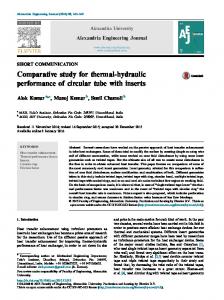
Fig. 1 Schematic of the CFMCHE, computational domain, and coordinate system
A complete three-dimensional 共3D兲 numerical analysis of counterflow microchannel heat exchangers with nanofluid as working fluid has not been accomplished so far. Therefore, the scope of the present paper is to study the effect of nanofluid on the heat transfer and pressure drop of CFMCHEs. The KKL model proposed by Koo and Kleinstreuer 关13,22兴 will be used for the thermal conductivity. Two different nanofluids, namely, Al2O3-water with a mean diameter of 47 nm and CuO-water with a mean diameter of 29 nm, will be compared. The fluid flow is in the laminar regime, and nanofluids are assumed to be Newtonian. The governing equations for heat transfer and flow will be solved using the finite volume approach in a collocated grid. The current research will evaluate the role of Brownian motion on the effectiveness of CFMCHE. Besides, the enhancement in pressure drop and performance index will be evaluated under a wide range of concentrations of nanoparticles and Reynolds numbers. It is shown that using nanofluids instead of pure fluid as working fluid causes both heat transfer and pressure drop increase, but the enhancement of pressure drop is small, especially for lower particle volume fractions.
2
Mathematical Modeling and Boundary Conditions
Full 3D conjugate heat transfer of two different nanofluids consisting of Al2O3 or CuO nanoparticles in water with different volume fractions in a counterflow microchannel heat exchanger with square cross sections has been considered. Figure 1 shows the geometry of the CFMCHE along with the coordinate system. Because of symmetry, only half of the geometry will be solved. The height, length, and width of each channel are 40 m, 10 mm, and 40 m, respectively. The solid material of CFMCHE is silicon, and the thermal conductivity is taken as a function of temperature. In the low speed microflow addressed in this study, it is assumed that all external walls are insulated, and the effects of radiation, compressibility, and natural convection are negligible. The fluid in each channel is a water-based nanofluid containing either Al2O3 or CuO nanoparticles. In order to be able to use the single phase approach, the diameters of nanoparticles are assumed
081801-2 / Vol. 133, AUGUST 2011
Downloaded From: http://heattransfer.asmedigitalcollection.asme.org/ on 02/07/2014 Terms of Use: http://asme.org/terms
Transactions of the ASME
to be less than 100 nm 共ultrafine solid particle兲. The inlet Reynolds number in each channel is below 1000; hence, flow in channels is assumed to be laminar. Cold and hot fluids with uniform temperatures of Tc = 300 K and Th = 325 K flow from the top and bottom channels, respectively. As the cold fluid flows through the top channel, it takes away heat from the bottom channel where the hot fluid flows. The outlets of each channel are open to the ambient with the atmospheric pressure. Furthermore, it is assumed that the mixture of water and nanoparticles is in thermal equilibrium, and they flow at the same velocity. The governing equations for an incompressible Newtonian liquid in the laminar regime and in steady state conditions are given by the following. Continuity equation:
u v w + + =0 x y z X-momentum equation:
冉
eff u
冊
共1兲
冉 冊 冉 冊 冉 冊
Y-momentum equation:
冉
冊
+
冊
冉 冊 冉 冊 冉 冊
+
v eff z z
共3兲
Z-momentum equation:
␥˙ =
冑再 冋 冉 冊 冉 冊 冉 冊 册 冉 2
eff
u x
2
+ eff
v y
2
+ eff
w z
2
+ eff
The effective density and capacitance of the nanofluid are calculated using the classical models for very dilute suspension available in literature 关28,29兴 and are expressed as
eff = 共1 − ␣兲 f + ␣ p
共8兲
共C p兲eff = 共1 − ␣兲共C p兲 f + ␣共C p兲 p
共9兲
where ␣ is the nanoparticle volume fraction. Index p and f stand for the nanoparticle and the base fluid, which is pure water in the present study. After analyzing several existing models for thermal conductivity and viscosity of nanofluid and comparing them against available experimental data in the literature, we found that the correlation given by Koo and Kleinstreuer 关13,22兴 for predicting thermal conductivity matched the experimental data better than the other existing models. This model takes into account the effect of Brownian motion, temperature, mean diameter, volume fraction of nanoparticles, and thermal conductivities of the base fluid and nanoparticles on nanofluid thermal conductivity at temperatures in the range of 300–325 K. Furthermore, Li and Kleinstreuer 关17兴 compared this model with the MSBM model proposed by Prasher for two different nanofluids, CuO-water and Al2O3-water, and found that it can predict the thermal conductivity of nanofluids accurately up to a volume fraction of 4%. Based on the KKL model 关13,22兴, the effective thermal conductivity of nanofluids is in the following form: Journal of Heat Transfer
冊 冉
冉
w eff z z
冊
冊 共4兲
Energy:
冉
共C p兲eff u
冊 冉 冊 冉 冊 冉 冊
T T T T T +v +w = keff + keff x y z x x y y +
T keff + ␥˙ 2 z z
共5兲
Heat transfer in CFMCHE is a conjugate problem, which combines heat conduction in the solid and convective heat transfer to the flowing fluid. The energy equation in the solid region is expressed as
冉 冊 冉 冊 冉 冊
Ts Ts Ts ks + ks + ks =0 x y z x y z
共2兲
v v v p v v +v +w =− eff + eff + x y z y x x y y
冉
w w w p w w +v +w =− eff + eff + x y z z x x y y
u u u p u u +v +w eff + eff =− + x y z x x x y y u + eff z z
eff u
冉
eff u
共6兲
where u , v , w are velocity components in the x , y , z directions, respectively. p and T are the pressure and temperature, respectively. Index s refers to the solid material of CFMCHE. ks is the thermal conductivity of the solid material. eff and C p,eff are the density and heat capacitance of the nanofluid, respectively. ␥˙ 2 is the viscous dissipation term, and it represents the time rate at which energy is being dissipated per unit volume through the action of viscosity. For an incompressible flow, it is written as follows:
u v + eff y x
冊 冉 2
+ eff
v w + eff z y
冊 冉 2
+ eff
w u + eff x z
冊冎 2
共7兲
共10兲
keff = kstatic + kBrownian
The first term is the conventional static part, which is the wellknown Hamilton–Crosser equation 关19兴 and can be defined as kstatic = k f
冋
共k p + 2k f 兲 − 2␣共k f − k p兲 共k p + 2k f 兲 + ␣共k f − k p兲
册
共11兲
The major enhancement in the thermal conductivity of nanofluids is due to the Brownian motion associated with the nanoparticles. The second term in the effective thermal conductivity model is the dynamic part, which originates from the particle Brownian motion and can be expressed as kBrownian = 5 ⫻ 104␣ f C p,f
冑
BT f共T, ␣兲 d p p
共12兲
where ␣, d p, and p are the nanoparticle volume fraction, nanoparticle mean diameter, and nanoparticle density, respectively. B is the Boltzmann constant 共1.3807⫻ 10−23 J / K兲. The functions f and  are to be determined semi-empirically. The model parameter f considers the augmented temperature dependent due to particle interactions, and function  represents the fraction of the liquid volume, which travels with a particle and decreases with the particle volumetric concentration due to the viscous effect of the moving particle. In Eq. 共12兲, the functions f and  can be combined to a new g-function that considers the influence of the AUGUST 2011, Vol. 133 / 081801-3
Downloaded From: http://heattransfer.asmedigitalcollection.asme.org/ on 02/07/2014 Terms of Use: http://asme.org/terms
multiparticle interaction, which depends on volume fraction, temperature, and particle diameter. This function is different for different base fluids; in the present study, only water-based nanofluids were considered because of the abundant experimental data. For example, for Al2O3-water and CuO-water nanofluids, the nonlinear g-function follows the following format 关30兴: g = 共a + b ln共d p兲 + c ln共␣兲 + d ln共␣兲ln共d p兲 + e ln共d p兲 兲ln共T兲 + 共m 2
+ h ln共d p兲 + i ln共␣兲 + j ln共␣兲ln共d p兲 + k ln共d p兲2兲
共13兲
where the a , b , c , d , e , g , h , i , j , k are constants. It should be noted that the g-function for CuO-water and Al2O3-water nanofluids generated r2 values of 98% and 96%, respectively, using benchmark experimental data sets 关30兴. In order to take into account the thermal interfacial resistance 共Rb兲 or the Kapitza resistance 关24,25,31,32兴, in the static part of the effective thermal conductivity model, an effective nanoparticle thermal conductivity was used to substitute the isolated nanoparticle thermal conductivity, Rb +
dp dp = k p k p,eff
共14兲
In the present study, we choose the value of Rb = 4 ⫻ 10−8 km2 / W according to Li and Kleinstreuer 关17兴. Koo and Kleinstreuer 关13兴 developed a new correlation for the dynamic viscosity of nanofluids as a function of temperature, mean nanoparticle diameter, density, viscosity of both base fluids and nanoparticles, and volume fraction,
eff = static + Brownian
共15兲
where static is the static part of viscosity and can be calculated by the Brinkman equation 关33兴 as follows:
static =
f 共1 − ␣兲2.5
冑
k bT f共T, ␣兲 d p p
共17兲
It is worth mentioning that the temperature dependent viscosity and thermal conductivity of pure water are as follows 关34兴: k f = 0.6共1 + 4.167 ⫻ 10−5T兲
共18兲
1713 T
共19兲
冉 冊
f = 2.761 ⫻ 10−6 exp
Boundary condition Inlet 共hot channel兲 共17-20-21-24兲 Outlet 共hot channel兲 共18-19-22-23兲 Inlet 共cold channel兲 共9-10-14-15兲 Outlet 共cold channel兲 共11-12-13-16兲 Fluid-solid interface 共9-10-11-12兲, 共13-14-15-16兲, 共17-18-19-20兲, and 共21-22-23-24兲 Fluid-solid interface 共19-20-21-22兲 and 共10-1113-14兲 Symmetry 共channel side兲 共9-12-15-16兲 and 共17-1823-24兲 Symmetry 共solid walls兲 共7-8-9-12兲, 共15-16-17-18兲, and 共2-3-23-24兲
u
v
w
T
Uin 0 0 u v w =0 =0 =0 x x x
Thi Tf =0 x
−Uin 0 0 u v w =0 =0 =0 x x x
Tci Tf =0 x
0
0
0
0
0
0
u =0 y
v=0
w =0 y
0
0
0
0
0
0
0
0
0
Side wall 共1-4-5-6兲 Top and bottom walls 共5-6-7-8兲 and 共1-2-3-4兲 Front and back walls 共1-2-24-21-20-17-16-13-1112-7-6兲 and 共3-4-5-8-9-10-1415-18-19-22-23兲
keff
Ts Tf = ks z z
keff
Ts Tf = ks y y Tf =0 y
Ts =0 y Ts ks =0 y Ts =0 ks z ks
0
0
Ts =0 x
0
共16兲
The dynamic term can be expressed as:
Brownian = 5 ⫻ 104␣ f
Table 1 Boundary conditions for the computational domain „Fig. 1…
the conjugate boundary conditions and resolve the viscous layer, the grids near the solid-liquid interfaces were refined. Furthermore, a large number of grid points are used near both ends of channels to resolve the flow developing regions. Figure 2 shows the schematic of the grid configuration used in the present simulation. Discretized equations were derived by integrating the governing equations over each control volume and then by approximating the resulting integrals using the multidimensional linear reconstruction approach 关36兴. The convective terms are calculated from face values by means of the QUICK 关37兴 scheme, and a second-order centered scheme was used to calculate diffusive
The temperature dependent thermal conductivity of silicon is as follows 关35兴: ksilicon = 290 − 0.4T
共20兲
Before the calculation starts, the boundary conditions must be set appropriately. In this study, a combination of wall, inlet, outlet, and symmetry boundary conditions is applied to the computational domain. All walls in contact with liquid flow are treated as no-slip boundary conditions. A constant and uniform velocity and temperature distributions are applied to the inlets of hot and cold channels. At the outlets, the static pressure is fixed, and the remaining flow variables are extrapolated from the interior of the computational domain. At the solid-liquid interface, the temperature continuity must be satisfied, so the heat fluxes at interfaces are used to relate the temperatures to each other. The appropriated boundary conditions for different parts of the CFMCHE model are given in Table 1.
3
Numerical Solution
Equations 共1兲–共6兲 with their associated boundary conditions were solved numerically using a finite volume code based on a collocated grid on a structured grid. In order to correctly capture
Fig. 2 Computational grid in CFMCHE
081801-4 / Vol. 133, AUGUST 2011
Downloaded From: http://heattransfer.asmedigitalcollection.asme.org/ on 02/07/2014 Terms of Use: http://asme.org/terms
Transactions of the ASME
Table 2 Grid independency study
Number of grid
⌬Pt 共kPa兲
% diff.
% diff.
¯ U h, o 共m/s兲
% diff.
Pure water
527,000 828,000 1,211,000 1,602,586
23,291.62 25,908.37 27,072.49 27,075.19
– 10.1 4.3 0.01
0.4682 0.5036 0.5245 0.5246
– 7.4 3.98 0.13
7.665 7.912 8.034 8.035
– 3.12 1.52 0.009
CuO-water
527,000 828,000 1,211,000 1,602,586
28,666.68 32,391.73 34,349.66 34,354.81
– 11.5 5.7 0.015
0.5197 0.5702 0.6079 0.6079
– 8.85 6.2 0.011
8.381 8.746 8.958 8.959
– 4.18 2.36 0.014
Al2O3-water
527,000 828,000 1,211,000 1,602,586
26,324.71 30,154.3 31,247.98 31,251.73
– 12.7 3.5 0.012
0.4767 0.5186 0.5518 0.5518
– 8.08 6.01 0.010
7.884 7.205 8.352 8.353
– 3.91 1.76 0.012
terms in the governing equations. The resulting scalar system of equations for dependent variables in each cell was solved using a point implicit 共Gauss–Seidel兲 linear equation solver in conjunction with an algebraic multigrid 共AMG兲 method. The SIMPLE 关38兴 共semi-implicit method for pressure-linked equations兲 algorithm was used to accomplish the pressure-velocity coupling. The convergence of codes was declared when the residual of each component of velocity vector, pressure, and temperature become 10−7, 10−5, and 10−11, respectively, Nx
Ny
Nz
兺 兺 兺 兩V共i, j,k兲 − V 共i, j,k兲兩 ⱕ 10
−7
共21a兲
−5
共21b兲
−11
共21c兲
0
i=0 j=0 k=0 Nx
Ny
Nz
兺 兺 兺 兩p共i, j,k兲 − p 共i, j,k兲兩 ⱕ 10 0
i=0 j=0 k=0
Nx
Ny
Nz
兺 兺 兺 兩T共i, j,k兲 − T 共i, j,k兲兩 ⱕ 10 0
i=0 j=0 k=0
where Nx, Ny, and Nz are the numbers of grids in the x, y, and z directions, respectively. The subscripts i, j, and k refer to ith, jth, and kth grid cells in the x, y, and z directions, respectively. Index 0 refers to the previous iteration. As the second criterion for convergence and to further ensure the accuracy of the computation, the total heat transfer and mass flow rates was examined through comparing the total input and output heats from the hot and cold channels and the total mass flow rate at inlets and outlets. The energy balance between the heat absorbed by the cold channel Qcold and the heat rejected by the hot channel Qhot can be used. The expressions for these two equations are ˙ c p兲cold共Tout − Tin兲cold Qcold = 共m
共22a兲
˙ c p兲hot共Tout − Tin兲hot Qhot = 共m
共22b兲
To obtain better accuracy in the simulations and grid sensitivity study, four hexahedral grids with total sizes of 527,000 共coarse兲, 828,000 共medium兲, 1,211,000 共fine兲, and 1,602,586 共very fine兲 were generated by discretizing the computational domain. Table 2 shows the comparison between the calculated effectiveness, pressure drop, and fully developed central velocity for four different grid sizes with both pure water and nanofluids 共␣ = 0.04兲 as working fluid. The grid independency test was performed for the higher Reynolds number 共worst Reynolds scenario兲. As seen, the maximum deviations among the third and fourth grids were less than 0.015%; hence, the solution becomes independent of the grid size in the third grid. Therefore, based on aforementioned parameters for the grid independency test, the Journal of Heat Transfer
third configuration with a total number of 1,211,000 cells seemed to be adequate to accurately capture fluid flow and heat transfer behaviors in CFMCHE, and further increasing the grids will have negligible effect on the solution and results. In order to check the accuracy and reliability of the numerical procedure, the results should validate with experimental data from literature. Wei et al. 关39兴 performed an experimental study to analyze the fluid flow and heat transfer in a stacked microchannel heat sink, which consists of two rows of rectangular microchannels with a counterflow configuration. The length and hydraulic diameter of micorchannels are 10 mm and 92 m, respectively. The thermal boundary conditions used in the experiment are uniform temperatures and constant velocities at the inlet of channels and constant heat flux of 70 W / cm2 subjected to the bottom wall of heat sink. We have simulated the same stack microchannel heat sink with the same boundary conditions and compared our numerical results with the experimental results. Figure 3 shows a comparison of calculated wall temperature distribution along the heat sink with the experimental data of Wei et al. based on the same dimensions and boundary conditions. Note that there are no data points located exactly at the ends of channels in the work of Wei et al. As seen, the results predicted by our numerical code match closely 共with the maximum deviation of 0.6%兲 with the results from available experimental data. A comparison of the experimental data and numerical results indicates that while the results of our numerical code accurately show the general trend of the experimental results, there is some disparity between the ex-
Fig. 3 Comparison of variation in wall temperature distribution along a counterflow heat sink with different total flow rates
AUGUST 2011, Vol. 133 / 081801-5
Downloaded From: http://heattransfer.asmedigitalcollection.asme.org/ on 02/07/2014 Terms of Use: http://asme.org/terms
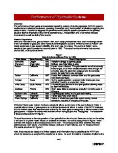
Fig. 4 The temperature in CFMCHE at three different Reynolds numbers with water as working fluid
perimental data and numerical results, especially near the end of the microchannel heat sink which numerical solution appears to have more difference with experimental data. Two possible explanations for this small difference are due to experiment uncertainty and end effects. Furthermore, there are two other factors that may contribute to the differences between computational fluid dynamics 共CFD兲 and experimental results. One is the fact that each of the nine measurement points indicates the average temperature over a 1 cm⫻ 0.55 mm region. The second factor is that the computational domain contains only the microchannel heat sink section. In the actual device, there are no ideal adiabatic regions especially at the front and back of MCHS, and these regions provide further heat conduction path to the environment. However, in the numerical model, adiabatic boundary conditions are used at the top wall, as well as back and front of MCHS. The above code verification tests indicate that the present numerical simulations are sufficiently valid for this study.
4
Results and Discussion
The numerical analysis was performed for the counterflow microchannel heat exchanger, and the results are presented in this study. The temperature contours in both solid and fluid regions of the computational domain are explored first. Then, the effects of different parameters affecting nanofluid viscosity and thermal conductivity on effectiveness are discussed. Afterward, the effects of the mentioned parameters on the performance index and pumping power are studied. Finally, the effect of Brownian motion on effectiveness is discussed. It is important to note that in all the presented results in Figs. 5–7, the effect of Brownian motion is considered. In microchannels, the transition from laminar to turbulent flow occurs early compared with the flow in ordinary channels. The Reynolds number in microchannels for the transition from laminar to turbulent is 1000, which is smaller than that for flow in conventional channels 关8兴. Therefore, the range of Reynolds numbers in this study is always below 1000, and the maximum value of Re is chosen to be 600 to ensure that the fluid flow is in the laminar regime. The Reynolds number is computed according to the hydraulic diameter of the channel, properties of water and water nanofluid, and inlet velocity. The Reynolds number is Re =
effuDh eff
共23兲
where Dh is the hydraulic diameter and can be calculated as Dh =
2HW H+W
共24兲
For the evaluation of the thermal performance of CFMCHE, it is necessary to understand the heat transfer physics in the CFMCHE,
and by analyzing the temperature field in the solid and fluid regions in the computational domain, a good insight into the heat transfer behavior can be obtained. Figure 4 shows the temperature contour in CFMCHE for water as the working fluid in three different inlet Reynolds numbers. Flow directions in the bottom and top channels are from left to right and right to left, respectively. It is clear that at the channel inlets 共x = 0 and x = L兲, the temperatures of the working fluids are originally uniform and change due to the development of the thermal boundary layers. As seen with increasing Reynolds number, the thermal developing length in each channel increases. It can be seen that in the hot channel, the temperature decreases gradually along the longitudinal x direction from the channel inlet to the outlet due to losing heat to the cold channel, whereas in the cold channel the temperature increases due to taking heat away from the hot channel. High heat flux regions are found near the channel inlets. Therefore, it can be concluded that regions with larger heat transfer coefficients are toward channel inlets. This is due to the thin thermal boundary layers in the developing regions of channels. Similar behaviors can be seen for the cases with nanofluid as working fluid. Under the conditions of the present study, assuming laminar, incompressible, and steady state, the thermal and hydrodynamic characteristics of CFMCHE such as pressure drop, effectiveness, and performance index are strongly affected by the Reynolds number, volume fraction of nanoparticles, and Brownian motion. For that reason, the effects of these parameters on hydrodynamic and thermal characteristics are discussed by using hydrodynamic and thermal models developed above. The heat exchanger effectiveness is the ratio of the actual heat transfer to the maximum possible heat that can be transferred, =
q qmax
共25兲
where qmax = Cmin共Thi − Tci兲
共26兲
q = Ch共Thi − Tho兲 = Cc共Tco − Tci兲
共27兲
and
where Thi, Tci, Tho, and Tco are the temperatures at the hot and cold channel inlets and the bulk temperatures at the hot and cold channel outlets. Cmin is equal to Ch or Cc, whichever is smaller. Cc and Ch are cold and hot heat capacity rates, respectively, and can be expressed as ˙ hC p Ch = m h
081801-6 / Vol. 133, AUGUST 2011
Downloaded From: http://heattransfer.asmedigitalcollection.asme.org/ on 02/07/2014 Terms of Use: http://asme.org/terms
共28a兲
Transactions of the ASME
˙ cC p Cc = m c
共28b兲
˙ h and m ˙ c are the mass flow rates through hot and cold where m channels, respectively. The thermal conductance can be calculated as follows: UA =
q ⌬TLMTD
共29兲
where ⌬TLMTD is the log mean temperature difference, which is defined as 共Tho − Tci兲 − 共Thi − Tco兲 共Tho − Tci兲 ln 共Thi − Tco兲
⌬TLMTD =
共30兲
Substituting Eqs. 共26兲 and 共27兲 into Eq. 共25兲, the effectiveness can be calculated as =
Ch共Thi − Tho兲 Cc共Tco − Tci兲 = Cmin共Thi − Tci兲 Cmin共Thi − Tci兲
共31兲
The inlet bulk temperature is considered constant for all models, whereas the outlet bulk temperature is calculated from the following equation:
Ti =
冕 冕
uiTidAi
Ai
,
i = ho,co
共32兲
uidAi
Ai
The pumping power required to circulate hot and cold fluids in a CFMCHE is P . P = Vh⌬Ph + Vc⌬Pc
共33兲
where ⌬P is the pressure drop across channels. V is the volumetric flow rate 共m3 / s兲. Subscripts h and c refer to hot and cold fluids. The volumetric flow rate and total pressure drop in CFMCHE are calculated from the following equations: V = UinA
共34兲
⌬Pt = ⌬Ph + ⌬Pc = 共Phi − Pho兲 − 共Pci − Pco兲
共35兲
where A and Uin are the area of the channel cross section and the inlet velocity, respectively. For performance assessment of the investigated CFMCHE, the performance index is represented by the ratio of CFMCHE effectiveness to the total pressure drop 关40兴. Performance index relates the hydrodynamic and thermal performance to obtain an indication about the overall exchanger performance,
=
⌬Pt
formance, the device is better to operate under low flow Reynolds numbers. Additionally, as seen with increasing volume fraction of nanofluids, the effectiveness increases. Figure 6 exemplifies the variation in pumping power with Reynolds number and volume fraction of nanoparticles. From this figure, it can be seen that at all values of Reynolds numbers, the CFMCHE with nanofluid as working fluid has higher values of pumping power with respect to pure water. A comparison between the pumping power of Al2O3-water and CuO-water nanofluids shows that the power required to drive CuO-water nanofluid to the channels is higher than that with Al2O3-water nanofluid. The results indicate that with increasing Reynolds number and volume fraction of nanoparticles, the required power to drive nanofluid in microchannels increases. As seen, the maximum pumping power enhancement occurred at Re= 600 and ␣ = 0.04 by about 21% and 14% for CuO and Al2O3 nanofluids compared with pure water, respectively. Furthermore, it is clear that the pumping power is not very sensitive to the volume fraction of nanoparticles at low Reynolds numbers. Figure 7 illustrates the effects of the Reynolds number, type of nanoparticles, and nanofluid volume fraction on the performance index. It demonstrates that a lower inlet Reynolds number results in higher thermal performance for CFMCHE. It is clear that for both types of nanoparticles with increasing volume fraction, the performance index decreases. As seen, in all cases, the flow with a Reynolds number of 200 has a high performance index, i.e., having higher overall hydrodynamic and thermal performance because it has a lower pressure drop and higher effectiveness. Also, at a constant Reynolds number and volume fraction, CFMCHE with Al2O3-water nanofluid has a higher performance index with
共36兲
Parameter is reasonable to evaluate the performance of CFMCHE with and without nanofluid since nanofluids usually increase both pressure drop and total heat transfer. Numerical results of the effectiveness obtained for the CFMCHE using different Reynolds numbers as well as both CuO and Al2O3 nanoparticles with different volume fractions are presented in Fig. 5. It can be seen that adding the low volume fraction of nanoparticles 共0.01–0.04兲 to the base fluid will lead to a significant increase in effectiveness at 0.8–4.9% and 2.7–13.7% for Al2O3 and CuO, respectively. In general, these enhancements are due to the higher thermal conductivity of nanoparticles and the role of the Brownian motion of nanoparticles on the enhancement of thermal conductivity. It can also be seen that with increasing Reynolds number, the effectiveness decrease in both cases with and without nanofluids. Therefore, to obtain higher thermal perJournal of Heat Transfer
Fig. 5 Effect of volume fraction on the effectiveness of the CFMCHE
Fig. 6 Effect of volume fraction on the pumping power of the CFMCHE
AUGUST 2011, Vol. 133 / 081801-7
Downloaded From: http://heattransfer.asmedigitalcollection.asme.org/ on 02/07/2014 Terms of Use: http://asme.org/terms
5
Conclusion
A counterflow microchannel heat exchanger with and without nanofluid as working fluid was investigated to identify the effects of the nanofluid volume fraction, Reynolds number, and Brownian motion on the thermal and hydrodynamic performance in the laminar flow regime. Furthermore, the influence of the inlet Reynolds number on the temperature contour in the heat exchanger is presented. It is proven that the addition of a small volume of nanoparticles can enhance the effectiveness of CFMCHE. Based on the dynamics of the nanofluid in CFMCHE and the thermal performance comparison, it is concluded that Brownian motion has a key role in effectiveness enhancement. According to the calculated results, we draw the following conclusions: Fig. 7 Effect of volume fraction on the performance index of the CFMCHE
respect to CuO-water. Furthermore, it is clear that the performance index is not very sensitive to the volume fraction of nanoparticles at higher Reynolds numbers. In this paper, the effective thermal conductivity and viscosity of nanofluids are calculated with two different formulas. The first one includes the effect of Brownian motion and uses keff = kstatic + kBrownian and eff = static + Brownian, as previously considered in the analysis. The second one neglects Brownian motion and uses keff = kstatic and eff = static. Table 3 shows the percentage increase in effectiveness with respect to pure water at three values of Reynolds numbers and volume fractions and for both Al2O3 and CuO nanoparticles when Brownian motion is considered in the simulation. From this table, it can be found that the Brownian motion of the nanoparticle has a major role in increasing the effectiveness of CFMCHE. As seen, the values of effectiveness are generally higher when Brownian motion is considered. For instance, at Re = 600 and ␣ = 0.04, the value of effectiveness increases by 5.2% and 15.9% with Brownian motion and by 2.2% and 5.1% without Brownian motion for Al2O3-water and CuO-water, respectively. These enhancements are due to the Brownian motion, which is a key mechanism in the thermal conductivity enhancement of nanofluids. It is observed that the influence of Brownian motion on effectiveness increases as the volume fraction increases. Also, the effect of Brownian motion on effectiveness is more significant in the higher values of Reynolds number. Based on the results of this study, we conclude that CFMCHEs with nanofluid as working fluid are good candidates for the next generation of two fluid CFMCHEs.
1. At a constant Reynolds number and volume fraction, CFMCHE with Al2O3-water nanofluid as working fluid has lower effectiveness and pumping power with respect to CuO-water nanofluid, while the performance index for Al2O3-water is higher than CuO-water. 2. Increasing the volume fraction of nanoparticles leads to increasing effectiveness and pumping power and decreasing performance index. 3. With decreasing Reynolds number, the effectiveness and performance index of CFMCHE increase, while the pressure drop and pumping power decrease. 4. The Brownian motion of nanoparticles is one of the main mechanisms in thermal conductivity enhancement and, consequently, effectiveness of CFMCHE. 5. The influence of Brownian motion on effectiveness increases as the volume fraction and Reynolds number increase.
Nomenclature A ⫽ area 共m2兲 C p ⫽ heat capacity of fluid at constant pressure 共J/kg K兲 Csi ⫽ heat capacity of silicon at constant pressure 共J/kg K兲 d p ⫽ particle diameter 共m兲 Dh ⫽ hydraulic diameter of the channel section 共m兲 H ⫽ height of channel 共m兲 h ⫽ heat sink height 共m兲 k ⫽ thermal conductivity 共W/m K兲 kb ⫽ Boltzmann constant 共j/K兲 L ⫽ microchannel length 共m兲 ˙ ⫽ mass flow rate 共kg/s兲 m P ⫽ pressure 共Pa兲
Table 3 The Brownian motion effect on effectiveness at various Re and ␣ Al2O3
CuO
␣=0
␣ = 0.01
␣ = 0.02
␣ = 0.04
␣=0
␣ = 0.01
␣ = 0.02
␣ = 0.04
Re= 200
Brownian Increase 共%兲 non-Brownian Increase 共%兲
0.798 0 0.798 0
0.804 0.8 0.801 0.4
0.809 1.4 0.803 0.7
0.819 2.5 0.808 1.3
0.798 0 0.798 0
0.820 2.8 0.804 0.8
0.832 4.3 0.810 1.6
0.851 4.6 0.821 2.9
Re= 400
Brownian Increase 共%兲 non-Brownian Increase 共%兲
0.628 0 0.628 0
0.636 1.3 0.631 0.5
0.643 2.4 0.634 1
0.655 4.3 0.640 1.9
0.628 0 0.628 0
0.663 5.6 0.636 1.3
0.681 8.4 0.643 2.4
0.707 12.5 0.656 4.4
Re= 600
Brownian Increase 共%兲 non-Brownian Increase 共%兲
0.525 0 0.525 0
0.533 1.6 0.528 0.6
0.540 2.9 0.531 1.2
0.552 5.2 0.536 2.2
0.525 0 0.525 0
0.562 7.1 0.532 1.4
0.581 10.8 0.539 2.8
0.608 15.9 0.551 5.1
081801-8 / Vol. 133, AUGUST 2011
Downloaded From: http://heattransfer.asmedigitalcollection.asme.org/ on 02/07/2014 Terms of Use: http://asme.org/terms
Transactions of the ASME
⌬Pt Pr q qmax Re
⫽ ⫽ ⫽ ⫽ ⫽
Rb T UA u,v,w
⫽ ⫽ ⫽ ⫽
Nx , N y , Nz V W x ⌬TLMTD
⫽ ⫽ ⫽ ⫽ ⫽
total pressure drop 共Pa兲 Prandtl number heat transfer rate 共W兲 maximum heat transfer rate 共W兲 Reynolds number based on the channel hydraulic diameter interfacial thermal resistance 共km2 / W兲 temperature 共K兲 thermal conductance 共W/K兲 velocity components in x, y, and z directions 共m/s兲 number of grids in x, y, and z directions volumetric flow rate 共m3 / s兲 width of channels 共m兲 Cartesian coordinates 共m兲 log mean temperature difference
Greek Symbols ␣ ⫽ ⫽ ␥˙ 2 ⫽ ⫽ ⫽ ⫽ ⫽
volume fraction of nanoparticles dynamic viscosity 共kg/ m s2兲 viscous dissipation kinematic viscosity 共m2 / s兲 density 共kg/ m3兲 effectiveness performance index 共1/Pa兲
Subscripts bf eff f ci co c h hi ho in nf out p s Si w 0 x y z
base fluid effective fluid inlet of cold channel outlet of cold channel cold hot inlet of hot channel outlet of hot channel inlet nanofluid outlet particle solid silicon wall previous iteration in the x direction in the y direction in the z direction
⫽ ⫽ ⫽ ⫽ ⫽ ⫽ ⫽ ⫽ ⫽ ⫽ ⫽ ⫽ ⫽ ⫽ ⫽ ⫽ ⫽ ⫽ ⫽ ⫽
References 关1兴 Vafai, K., and Zhu, L., 2002, “Two-Layered Micro Channel Heat Sink, Devices and Systems Incorporating Same,” U.S. Patent No. 6,457,515. 关2兴 Vafai, K., and Zhu, L., 2004, “Multi-Layered Micro Channel Heat Sinks,” U.S. Patent No. 6,675,875. 关3兴 Vafai, K., and Khaled, A. R., 2010, “Methods and Devices Comprising Flexible Seals, Flexible Microchannels, or Both for Modulating or Controlling Flow and Heat,” U.S. Patent No. 7,770,809. 关4兴 Vafai, K., and Zhu, L., 1999, “Analysis of Two-Layered Micro-Channel Heat Sink Concept in Electronic Cooling,” Int. J. Heat Mass Transfer, 42共12兲, pp. 2287–2297. 关5兴 Albakhit, H., and Fakheri, A., 2005, “A Hybrid Approach for Full Numerical Simulation of Heat Exchangers,” Proceedings of the ASME Heat Transfer Summer Conference, San Francisco, CA, Jul. 17–22. 关6兴 Brandner, J. J., Anurjew, E., Buhn, L., Hansjosten, E., Henning, T., Schygulla, U., Wenka, A., and Schubert, K., 2006, “Concept and Realization of Microstructure Heat Exchangers for Enhanced Heat Transfer,” Exp. Therm. Fluid Sci., 30, pp. 801–809. 关7兴 Kang, S. W., and Tseng, S. C., 2007, “Analysis of Effectiveness and Pressure Drop in Micro Cross-Flow Heat Exchanger,” Appl. Therm. Eng., 27共5–6兲, pp. 877–885. 关8兴 Hasan, M. I., Rageb, A. A., Yaghoubi, M., and Homayoni, H., 2009, “Influence of Channel Geometry on the Performance of a Counter Flow Microchan-
Journal of Heat Transfer
nel Heat Exchanger,” Int. J. Therm. Sci., 48共8兲, pp. 1607–1618. 关9兴 Mathew, B., and Hegab, H., 2010, “Application of Effectiveness-NTU Relationship to Parallel Flow Microchannel Heat Exchangers Subjected to External Heat Transfer,” Int. J. Therm. Sci., 49共1兲, pp. 76–85. 关10兴 Godson, L., Raja, B., Lal, D., and Wongwises, S., 2010, “Enhancement of Heat Transfer Using Nanofluids—An Overview,” Renewable Sustainable Energy Rev., 14, pp. 629–641. 关11兴 Lee, S., and Choi, S. U. S., 1996, “Application of Metallic Nanoparticle Suspensions in Advanced Cooling Systems,” Proceedings of the Recent Advances in Solids/Structures and Application of Metallic Materials, ASME Paper No. PVP 342/MD-72, pp. 227–234. 关12兴 Chein, R., and Huang, G., 2005, “Analysis of Microchannel Heat Sink Performance Using Nanofluids,” Appl. Therm. Eng., 25, pp. 3104–3114. 关13兴 Koo, J., and Kleinstreuer, C., 2005, “Laminar Nanofluid Flow in MicroheatSinks,” Int. J. Heat Mass Transfer, 48, pp. 2652–2661. 关14兴 Jang, S. P., and Choi, S. U. S., 2006, “Cooling Performance of a Microchannel Heat Sink With Nanofluids,” Appl. Therm. Eng., 26, pp. 2457–2463. 关15兴 Chein, R., and Chuang, J., 2007, “Experimental Microchannel Heat Sink Performance Studies Using Nanofluids,” Int. J. Therm. Sci., 46共1兲, pp. 57–66. 关16兴 Tsai, T. H., and Chein, R., 2007, “Performance Analysis of Nanofluid-Cooled Microchannel Heat Sinks,” Int. J. Heat Fluid Flow, 28, pp. 1013–1026. 关17兴 Li, J., and Kleinstreuer, C., 2008, “Thermal Performance of Nanofluid Flow in Microchannels,” Int. J. Heat Fluid Flow, 29, pp. 1221–1232. 关18兴 Wang, X.-Q., and Mujumdar, A. S., 2007, “Heat Transfer Characteristics of Nanofluids: A Review,” Int. J. Heat Mass Transfer, 46, pp. 1–19. 关19兴 Hamilton, R. L., and Crosser, O. K., 1962, “Thermal Conductivity of Heterogeneous Two Component Systems,” I & EC Fundamentals, Vol. 1, pp. 187– 191. 关20兴 Maxwell, J. C., 1904, A Treatise on Electricity and Magnetism, 2nd ed., Oxford University Press, Cambridge, UK. 关21兴 Jang, S. P., and Choi, S. U. S., 2004, “The Role of Brownian Motion in the Enhanced Thermal Conductivity of Nanofluids,” Appl. Phys. Lett., 84, pp. 4316–4318. 关22兴 Koo, J., and Kleinstreuer, C., 2004, “A New Thermal Conductivity Model for Nanofluids,” J. Nanopart. Res., 6, pp. 577–588. 关23兴 Xuan, Y., Li, Q., and Hu, W., 2003, “Aggregation Structure and Thermal Conductivity of Nanofluids,” AIChE J., 49, pp. 1038–1043. 关24兴 Prasher, R., Bhattacharya, P., and Phelan, P. E., 2006, “Brownian-MotionBased Convective-Conductive Model for the Effective Thermal Conductivity of Nanofluids,” ASME J. Heat Transfer, 128, pp. 588–595. 关25兴 Jang, S. P., and Choi, S. U. S., 2007, “Effects of Various Parameters on Nanofluid Thermal Conductivity,” ASME J. Heat Transfer, 129, pp. 617–623. 关26兴 Kleinstreuer, C., and Li, J., 2008, “Discussion: “Effects of Various Parameters on Nanofluid Thermal Conductivity 共Jang, S. P., and Choi, S. D. S., 2007, ASME J. Heat Transfer, 129, pp. 617–623兲,” ASME J. Heat Transfer, 130共2兲, p. 025501. 关27兴 Vajjha, R. S., and Das, D. K., 2009, “Experimental Determination of Thermal Conductivity of Three Nanofluids and Development of New Correlations,” Int. J. Heat Mass Transfer, 52, pp. 4675–4682. 关28兴 Xuan, Y., and Roetzel, W., 2000, “Conceptions for Heat Transfer Correlations of Nanofluids,” Int. J. Heat Mass Transfer, 43, pp. 3701–3707. 关29兴 Pak, B. C., and Cho, Y. I., 1998, “Hydrodynamic and Heat Transfer Study of Dispersed Fluids With Submicron Metallic Oxide Particle,” Exp. Heat Transfer, 11, pp. 151–170. 关30兴 Li, J., 2008, “Computational Analysis of Nanofluid Flow in Microchannels With Applications to Micro-Heat Sinks and Bio-MEMS,” Ph.D. thesis, MAE Department, NCSU, Raleigh, NC. 关31兴 Xuan, Y., Li, Q., Zhang, X., and Fujii, M., 2006, “Stochastic Thermal Transport of Nanoparticle Suspensions,” J. Appl. Phys., 100, p. 043507. 关32兴 Xue, Q. Z., 2006, “Model for the Effective Thermal Conductivity of Carbon Nanotube Composites,” Nanotechnology, 17, pp. 1655–1660. 关33兴 Brinkman, H. C., 1952, “The Viscosity of Concentrated Suspensions and Solutions,” J. Chem. Phys., 20, pp. 571–581. 关34兴 Kwak, H. S., Kin, H., Jae, M. H., and Tae-Ho, S., 2009, “Thermal Control of Electroosmotic Flow in a Microchannel Through Temperature-Dependent Properties,” J. Colloid Interface Sci., 335, pp. 123–129. 关35兴 Glassbrenner, C. J., and Slack, G. A., 1964, “Thermal Conductivity of Silicon and Germanium From 3K to the Melting Point,” Phys. Rev., 134, pp. A1058– A1069. 关36兴 Barth, T. J., and Jesperson, D., 1989, “The Design and Application of Upwind Schemes on Unstructured Meshes,” AIAA Paper No. 89-0366. 关37兴 Leonard, B. P., 1995, “Order of Accuracy of Quick and Related ConvectionDiffusion Schemes,” Appl. Math. Model., 19, pp. 640–653. 关38兴 Vandoormall, J. P., and Raithby, G. D., 1984, “Enhancements of the Simple Method for Predicting Incompressible Fluid Flow,” Numer. Heat Transfer, 7, pp. 147–163. 关39兴 Wei, X., Joshi, Y., and Patterson, M., 2007, “Experimental and Numerical Study of Stacked Microchannel Heat Sink for Liquid Cooling of Microelectronic Devices,” ASME J. Heat Transfer, 129, pp. 1432–1444. 关40兴 Farid, M., Smith, R., Sabbah, R., and Al-Hallaj, S., 2007, “Miniaturized Refrigeration System With Advanced PCM Micro Encapsulation Technology,” Fifth Conference on Nanochannels, Microchannels, and Minichannles, Puebla, Mexico.
AUGUST 2011, Vol. 133 / 081801-9
Downloaded From: http://heattransfer.asmedigitalcollection.asme.org/ on 02/07/2014 Terms of Use: http://asme.org/terms