Aug 2, 1993 - September 1991. Center for Research on Parallel Computation. Rice University. 6100 South Main Street. CRPC - MS 41. Houston, TX 77005.
Thermal Simulation of Pipeline Flow Philip Keenan
CRPC-TR91187 September 1991
Center for Research on Parallel Computation Rice University 6100 South Main Street CRPC - MS 41 Houston, TX 77005
Revised: August, 1993. Presented at SIAM Annual Meeting (July, 1990) in Chicago.
Thermal Simulation of Pipeline Flow Philip T. Keenan� August 2, 1993 Abstract
A new numerical method for studying one dimensional uid ow through pipelines is presented and analyzed. This work extends in a certain direction the collocation method described by Luskin[\An Approximation Procedure for Nonsymmetric, Nonlinear Hyperbolic Systems with Integral Boundary Conditions", SIAM J. Numer. Anal. 1976.]. The pressure and velocity of an isothermal uid in a pipeline can be described by a coupled pair of nonlinear rst order hyperbolic partial di�erential equations. When thermal e�ects are important a third equation for temperature is added. While Luskin's method works well for the isothermal situation he discussed, it does not apply in certain common cases when thermal e�ects are modeled. The analysis of this new method shows how the di�culties that come from the application of standard collocation can be overcome. Experiments indicate that this method is a substantial improvement over standard collocation. It also describes an approach to analyzing nonlinear evolution equations with smooth solutions which produces convergence theorems about the nonlinear system from the corresponding linear theorems with relatively little extra work. This technique also yields an H 1 estimate in the isothermal case.
Key Words: rst order hyperbolic, collocation method, upwinding AMS(MOS) subject classi cation: 65N35
� Department of Mathematics, University of Chicago, supported in part by a Graduate Fellowship from the National Science Foundation.
1
Contents 1 Introduction 2 The Partial Di�erential Equations 3 The Numerical Method 3.1 3.2 3.3 3.4
Rewriting the Partial Di�erential Equations Boundary Conditions : : : : : : : : : : : : : Discrete Notation : : : : : : : : : : : : : : : De ning the Numerical Method : : : : : : :
: : : :
: : : :
: : : :
: : : :
: : : :
: : : :
: : : :
: : : :
: : : :
: : : :
: : : :
: : : :
: : : :
3 3 5
: 5 : 7 : 7 : 10
4 The General Framework
11
5 6 7 8
16 17 19 26
4.1 The degenerate case : : : : : : : : : : : : : : : : : : : : : : : : : : : 12 4.2 The non-degenerate case : : : : : : : : : : : : : : : : : : : : : : : : : 15
Theoretical Results Computational Results Remarks and Extensions Error Analysis 8.1 8.2 8.3 8.4 8.5
The Error Equation : : : Diagonalization : : : : : : The 27 Product Terms : : The Induction Hypothesis The Gronwall Induction :
: : : : :
: : : : :
: : : : :
: : : : :
2
: : : : :
: : : : :
: : : : :
: : : : :
: : : : :
: : : : :
: : : : :
: : : : :
: : : : :
: : : : :
: : : : :
: : : : :
: : : : :
: : : : :
: : : : :
: : : : :
: : : : :
: : : : :
: : : : :
: : : : :
26 32 36 43 45
1 Introduction Thermal modeling of uid ow through pipelines is increasingly necessary as practical engineering applications demand greater delity between model and reality. When pipeline simulators are used for leak detection, for instance, real time thermal modeling may be required to distinguish leaks from pressure changes due to heat exchange with the environment. Thermal modeling may also be important in attempting to optimize pipeline usage for maximum economic utility. Isothermal uid ow in pipelines is described by a pair of coupled rst order nonlinear hyperbolic partial di�erential equations for pressure and velocity. In 1978 Mitchell Luskin[2] described and analyzed a numerical method applicable to a large class of systems, including the isothermal pipeline case. The method relies upon the fact that the eigenvalues of the matrix which determines the characteristic directions are both bounded far away from zero. In its simplest version, the method uses piecewise linear approximations in space and time and can be described as box centered collocation. Thermal e�ects in pipeline ow introduce a third coupled equation for temperature and a resulting third eigenvalue which is small or possibly zero. It can be shown that straightforward application of collocation methods to problems with small eigenvalues produces numerical instability. This work presents a generalization to straightforward collocation which allows the inclusion of thermal e�ects. We approximate the temperature with velocity upwinded piecewise constants in space, which recti es the stability problems but substantially increases the complexity of the resulting analysis. We begin with formal statements of the problem, the method, the theorems and some numerical results. The proofs are postponed to Section 8.
2 The Partial Di�erential Equations We remark that the thermal pipeline equations are but one instance of a more general set of coupled rst order hyperbolic partial di�erential equations which may be solved using the methods indicated below. In particular, Luskin's method applies to systems with large eigenvalues, and my method applies to systems with several large and one small eigenvalue. The primary subject of the investigation here is the numerical approximation of the solution. There does not yet exist a complete theory for the system of nonlinear partial di�erential equations describing the thermal pipeline model. Therefore, we make certain assumptions about the nature of the solutions which appear reasonable for pipelines. In particular, we assume that the ow speed is much smaller than the speed of sound and that no shocks are present. 3
Luskin and Blake[3] have demonstrated the existence of smooth solutions for systems such as the isothermal equations. We state the equations for the Plug Flow model of pipeline uid ow; we are outside the region of laminar ow but in a regime where shocks are not generally observed. These equations have been known for a very long time; Bernoulli described versions in the 1800's. The three dependent variables are the pressure p = p(x; t), the velocity v = v(x; t), and the temperature T = T (x; t). Here x 2 [0; E ] and t � 0, where E is the length of the pipeline. We will restrict attention to a rigid horizontal pipe, though extensions incorporating gravitational e�ects are straightforward. To be precise, we measure the pressure and temperature at the center of a cross section of the pipe, while the velocity is averaged over the cross section. From these three variables we also compute the density � = �(p; T ), and the speci c internal energy E = E (p; T ), from tables of thermodynamic constants or an equation of state for the uid of interest. Three partial di�erential equations connect the three independent variables. First is the Conservation of Mass equation,
�t + (�v)x = 0: The subscripts denote partial di�erentiation. This states that no uid is created or destroyed. Next is the Conservation of Momentum equation, which is Newton's law of force balance: (�v )t + (�v 2)x + px + �f2jDv jv = 0: Here f is a dimensionless positive constant called the coe�cient of friction; other forms could also be used for the frictional dissipation term. The parameter D is the internal diameter of the pipe. Finally we have the Conservation of Energy equation, which refers to the total kinetic and internal energy of the uid: (�E + �v 2=2)t + ((�E + �v 2=2)v )x + (pv )x ? q = 0: Here q is a function of x and t describing the ow of heat into or out of the pipeline through its walls. The equations are to be interpreted in some consistent set of units. The plug ow model has been validated in engineering practice for pipelines carrying such diverse uids as natural gas, crude oil and water; see [5] for references. These equations can be thought of as forming a di�erential-algebraic system. Although some such systems have been analyzed, a general theory is still lacking. 4
The equations above contain the one-dimensional equations of gas dynamics as the special case q = f = 0; hence under certain conditions the solution can involve shocks. The method presented here is appropriate for the solutions which are important in pipeline applications, but this method would probably not be a good choice if shocks were present. We choose to compute with pressure, velocity and temperature, rather than density, mass ow and internal energy, because the latter variables may be almost discontinuous across the boundaries between di�erent batches of uid in a pipeline. Pipelines frequently carry several di�erent uids in successive batches. Some pipelines also contain multiple phases, gaseous as well as liquid components, but we ignore such complications here. Since we are looking for smooth solutions and are using continuous functions to approximate the computing variables, pressure and velocity are appropriate choices. In addition, the discontinuous piecewise constants we use for temperature are also appropriate since contact discontinuities in temperature are possible with appropriate boundary conditions. The asymptotic accuracy of this method will be limited to rst order by the presence of the piecewise constant approximation for temperature. However, we still expect the method to perform well in practice. Temperature e�ects are generally only a small correction to the pressure and velocity system, as indicated by the wide utility of Luskin's pressure and velocity method. Moreover large temperature changes tend to take place on a much slower time scale than that needed to resolve sonic e�ects. Thus we expect that in practice the rst order errors in temperature will have a small coe�cient compared to the second order pressure and velocity errors, leading to better than rst order convergence rates at practical mesh sizes.
3 The Numerical Method
3.1 Rewriting the Partial Di�erential Equations
We begin by formulating the di�erential system. After expanding the equations in terms of p, v , and T , we make some simple substitutions to get
�p(pt + vpx ) + �T (Tt + vTx) + �vx = 0;
(1)
vt + vvx + �1 px + f2jvDjv = 0;
(2)
Ep(pt + vpx) + ET (Tt + vTx) + �1 pvx ? f j2vDjv ? �q = 0: 2
(3)
We next diagonalize the time derivative term, putting the equations into standard form. This has the e�ect of removing as much temperature dependence as 5
possible from the pressure and velocity equations, which is helpful since temperature terms will be the main stumbling block in the analysis. In particular, we analytically invert the 2 � 2 matrix
0 1 � � B@ p T CA : Ep ET
The inverse is
where
0 1 E ? � T C 1B T @ k ?Ep �p A ; k = �pET ? Ep �T :
The quantity k is positive for uids such as natural gas. We write the resulting system of PDE's as � x = F; ut + Au where
(4)
u = (p; v; T )tr;
and A� and F are known functions. Note that the system is non-linear: A� and F depend on u(x; t); in general they could also depend on x and t explicitly. In more detail, for some functions a, b, and c, we can write
0 1 v a 0 BB CC A�(u) = B B@ b v 0 CCA : 0 c v
The characteristic polynomial of A is ch(�) = (v ? �)((v ? �)2 ? ab): p Let s = ab. Then the eigenvalues of A� are
�1 = s + v; �2 = ?s + v; �3 = v: 6
(5)
These represent three modes, namely, two high speed components called sound waves moving in opposite directions, and one mode moving with the underlying
uid velocity. For this reason s is called the sonic velocity. Note that we have assumed s � jv j over the operational range of the pipe. This keeps the eigenvalues distinct. For most pipelines, jv j � 0:01s. It is easy to see that because the third eigenvalue can vanish, straightforward application of collocation to equations of this form can give bizarre behavior; in the case of v = 0 a change in temperature at one end of the pipe would be instantly propagated as a saw tooth wave down the entire pipe.
3.2 Boundary Conditions We need to specify initial conditions for pressure, velocity and temperature. Thus we assume u(x; 0) = u0(x); for all x 2 [0; E ] where u0 is a given, smooth, vector function. In addition, we need to specify one boundary condition for each in- owing component of the solution, at each end of the pipe. As a simple example, we may specify pressure at each end of the pipe, and temperature at each inlet end. That is, we set
p(0; t) = pl(t); p(E; t) = pr (t);
where pl and pr are given smooth functions. Depending on the sign of the velocity we make analogous speci cations for temperature at both ends, one end, or not at all. In particular, we specify
T (0; t) = Tl(t) whenever v(0; t) > 0, and T (E; t) = Tr (t) whenever v(E; t) < 0. These conditions make the problem well-posed. They are representative of the conditions for which the theorems and analysis hold. In Section 4 we will describe the general class of boundary conditions which we consider.
3.3 Discrete Notation We now introduce some notation for describing the discrete problem. Given a positive integer N , let
Px = fx ; x ; : : :; xN g; 0
1
7
where xk = kh, h = E=N and E is the length of the pipe. This gives a uniform partition of [0; E ] into N intervals. We write the spatial midpoints as
xj+1=2 = (xj + xj+1 )=2: We collect these with
P^x = fxj
: j = 0; 1; : : :; N ? 1g: Next we de ne two shift operators on [0; E ]: =
+1 2
8 > > < xj x = > xN > :
=
+1 2
+
xj+1
and
8 > > < xj? = x? = > x > :
1 2
0
xj
for x = xj , j < N , for x = xN , for x 2 (xj ; xj +1), for x = xj , j > 0, for x = x0, for x 2 (xj ; xj +1 ).
If u is any function of x, we let
u+ (x) = u(x+); u? (x) = u(x?): De ne
4x = x+ ? x? ;
and the centered divided di�erence operator by
@x u = (u+ ? u?)=4x: Note that for our uniform space partition, 4x = h everywhere except at x = 0 and x = E . We also use a centered approximation to u given by
u;c = (u+ + u?)=2: We adopt analogous time operators using superscripts, based on a set of time levels Pt = ft0; t1; : : :; tM g; 8
where t0 = 0, tM = � is some xed nal time, and tn < tn+1 for each n. This gives a possibly non-uniform partition of [0; � ] into M time steps. Given � 2 [0; 1] we set
tn+� = �tn+1 + (1 ? �)tn ; and write the set of theta-weighted time levels as
P^t = ftn � : n = 0; 1; : : :; M ? 1g: +
We also de ne Finally,
u;� = �u+ + (1 ? �)u? :
Q^ = P^x � P^t;
is the set of space time points at which we will apply collocation. Except in Section 7 we assume the time partition is uniform, with
tn+1 ? tn = 4t = �=M for all n. For example, using this notation we can write
@tu(x; t) + @x u(x; t) = 0 for all (x; t) 2 Q^, by which we mean
u(xj+1=2; tn+1 ) ? u(xj+1=2; tn) u(xj+1 ; tn+� ) ? u(xj ; tn+� ) + = 0; tn+1 ? tn xj+1 ? xj for all j = 0; 1; : : :; N ? 1, and n = 0; 1; : : :; M ? 1. We will henceforth suppress the (x; t) arguments to all functions. We will need to de ne several bilinear forms, including the usual L2 (0; E ) inner
product
(f; g )L2 =
ZE 0
and two discrete approximations to it,
m2 = l2 =
f g dx;
X P
f g 4x;
^x
X Px
f g 4x:
With these are associated the norms and semi-norms 9
q kf kL2 = (f; f )L2 ; q jf jm2 = m2 ; q jf jl2 = l2 :
Finally, when dealing with functions of several variables we will use tensor indexing notation and the summation convention. Thus if A = (Aij ) is a matrix function of a vector u, then we write
Aij;kl = @u@ @u@ Aij ; k l th where Aij is the element of A in the i row and j th column. If B is another matrix
of compatible dimensions we write
Aik Bkj =
X k
Aik Bkj :
3.4 De ning the Numerical Method
Returning to the problem at hand, we recall u = (p; v; T )tr: The numerical method involves approximating u by U , where pressure and velocity are piecewise linear in space and in time and temperature is discontinuous piecewise constant in space and piecewise linear in time. Temperature is also velocity advected or upwinded. Upwinding allows us to make temperature well de ned at the knots, which further allows us to use all the above indexing and discrete derivative notations. U3n is upwinded based on U2n?1 , by the rule that
8 > < U n (xj = ) if U n? (xj ) < 0; n U (xj ) = > : U n (xj? = ) if U n? (xj ) � 0: 3
+1 2
2
3
1 2
2
3
1
1
We choose U 0 based on the initial condition u0 ; it can be the interpolant of u0 into the spaces de ning U . To compute U (tn+1 ) from U (tn ), we discretize equation (4). Before doing so, we rst make the substitution vTx = (vT )x ? vx T: This is useful in the analysis in make the upwinding of temperature work out. In writing this term we will make use of two important matrices,
1 0 1 0 0 CC BB B P =B 0 1 0 C CA ; @ 0 0 0 10
(6)
� , so that and Q = I ? P where I is the 3 � 3 identity matrix. We also let A = AP A� = AP + �3Q. Next, writing u = u0 + (u ? u0 ) where u ? u0 is small, we Taylor expand around u0 and ignore higher order terms beginning with (u ? u0)2 . Thinking of u0 as u(x; tn) and u as u(x; tn+� ), we have an equation we can discretize. We do so with collocation at each point of Q^ . We write the resulting equations in tensor notation, with k = 1; 2; 3: All the coe�cient functions A and F in this equation are evaluated at U ? . We thus obtain
@tUk + Akj @x Uj + �k3 @x (U2?U3 ) ? �k3 U3 @x U2? + Akj;i @xUj? (Ui ? Ui? ) + �k3 @x ((U2 ? U2? )U3? ) ? �k3 U3? @x (U2 ? U2? ) = fk + fk;i (Ui ? Ui? ) at every point in Q^ . (7) One can view this as a discretization of the integral average of the PDE over [xj ; xj +1 ] � [tn ; tn+1 ]. We also discretize the boundary conditions of Section 3.2. We set n+1 ); U1n;+1 0 = pl (t
U1n;N+1 = pr (tn+1 ):
To handle the temperature boundary condition we set n+1 U3n;+1 ?1=2 = Tl(t );
U3n;N+1+1=2 = Tr (tn+1 );
and let the usual rule for upwinding determine when this determines U3;0 and U3;N . We should mention that the system (7) is soluble numerically; it produces a nonsingular square matrix system which has a small bandwidth. To facilitate upwinding of temperature it is convenient to let the midpoint temperature values be variables as well as the pressure, velocity and temperature knot values. Under plausible assumptions the variable ordering pj ; Tj ; vj ; Tj +1=2 produces a matrix which can be solved without pivoting.
4 The General Framework The thermal pipeline equations formulated in Section 3 are but one instance of a more general set of equations to which my method applies. In this section we state the general problem we propose to solve, which we will call the degenerate case, because of the possibility of one eigenvalue becoming arbitrarily small or even changing 11
sign. For comparison we also state a version of Luskin's 1978 equations which we call the non-degenerate case. This is the case where all the eigenvalues are bounded away from zero, and in the pipeline context corresponds to assuming some functional form for temperature and then solving only the pressure and velocity equations. The reader interested more in pipelines than in mathematics may skip this section; such a reader should substitute \thermal pipeline equations" for \degenerate case" and \pressure-velocity equations" for \non-degenerate case" hereafter. We consider the following system of � rst order hyperbolic nonlinear partial di�erential equations:
ut + A�(u)ux = F (u); (8) where u(x; t) 2 R� , x 2 [0; E ], t 2 [0; � ], A� is a � � � matrix, and F is a �-vector, and where A� and F are smooth functions of x, t, and u(x; t). We are given the initial condition
u(x; 0) = u0 (x) for all x 2 [0; E ],
(9) as well as suitable boundary conditions. We need one boundary condition at (0; t) for each eigenvalue of A� which is positive there, and one boundary condition at (E; t) for each eigenvalue of A� which is negative there. We describe these more fully in the following two special cases, based on the form of the matrix A�. In both the following cases we assume that all the eigenvalues of A� are real and that there exists a smooth and bounded transformation matrix S (u(x; t); x; t) with � is diagonal. smooth and bounded inverse such that S ?1 AS
4.1 The degenerate case
Suppose that all the eigenvalues but one of A� are uniformly bounded away from zero. Suppose also that A� has the form
0 A A�(u) = B @ A
11 21
1 0C A;
�
(10)
where � is that one eigenvalue which is not bounded away from zero. Here A11 represents a � ? 1 � � ? 1 submatrix, and A21 a 1 � � ? 1 submatrix. Suppose also that @�(u) = 0; (11) @u �
so that � does not depend on u� . Finally, if the eigenvalues of A� are f�1; : : :; ��?1 ; �g, then suppose j�ij � j�j for 1 � i � � ? 1. (12) 12
The boundary conditions for u� are handled exactly as was done for temperature in the previous section, namely we specify
u�(0; t) = Tl(t); whenever �(0; t) > 0, and u� (E; t) = Tr(t); whenever �(E; t) < 0. ?1 A11S11 is the diagonal matrix Now let S11 be a matrix such that S11 diag(�1; : : :; ��?1) where �i > 0 for 1 � i � k and �i < 0 for k + 1 � i � � ? 1. Then we must specify k boundary conditions at x = 0 and � ? 1 ? k at x = E . At
each boundary the ingoing components must be speci ed as an a�ne linear function of the outgoing ones, in order for the boundary conditions to be realizable. Let v = (u1 ; : : :; u�?1). Then we allow the following boundary conditions:
R1v(0; t) = va(t); R2v(E; t) = vb(t);
where va and vb are given smooth vector functions, and R1 is a constant k � � ? 1 matrix and R2 is a constant � ? 1 ? k � � ? 1 matrix, and R1 and R2 satisfy
R1S11?1 = (E11jE12); R2S11?1 = (E21jE22); where E11 and E22 are non-singular k � k and � ? 1 ? k � � ? 1 ? k matrices,
respectively.
Assumption 1 We assume that the system given by (8), with initial data given
by (9) and boundary data as described above, does have a smooth solution u for all t 2 [0; � ].
For example in the pipeline case the degenerate eigenvalue is the ow velocity, which is much smaller than the sonic velocity. It arises in the temperature equation but is independent of temperature. In addition Tx does not appear in the p and v equations. This was achieved by an analytic transformation prior to discretizing ?1 the equations. This special form seems important to the analysis. The matrix S11 has all entries non zero, so choosing R1 = R2 = (1; 0) yields non zero scalars for E11 and E22. This illustrates the acceptability of the pressure boundary conditions described in Section 3.
De nition 1 When all the above suppositions hold, we say that we are considering the degenerate case of (8). In this case we also de ne a � � � matrix P as follows: P = diag(1; 1; : : :; 1; 0): 13
(13)
� . We now de ne Q = I ? P , where I is the � � � identity matrix, and A = AP With this notation, we can write the degenerate case of (8) as
ut + A(u)ux + �(u)Qux = F (u):
(14)
Equation (14) has the form
ut + G(u; ux) = 0; where G is a smooth function of 2� arguments. Applying Taylor's theorem and using the summation convention that repeated subscripts of i, j , k, or l indicate summation from 1 to �, we have Gk (v; w) = Gk (v0 ; w0) + Gk;i (v0 ; w0)(vi ? v0i ) + Gk;i+� (v0; w0)(wi ? w0i) + Quad; where Quad contains only terms quadratic in v ? v0 or w ? w0. In particular, using v = u(x; t), w = ux (x; t), v0 = u0(x; t0), and w0 = u0x (x; t0), (14) becomes
ukt + Akj (u0)uxj + Akj;i (u0)u0xj (ui ? u0i ) + �(u0)�k� u�x + �;i(u0 )�k� u0�x (ui ? u0i) = Fk (u0) + Fk;i (u0)(ui ? u0i ) + Quad:
(15)
We now choose u0 (x; t0) = u(x; t? ), and evaluate at all points in Q^. We also use the identity abx = (ab)x ? ax b on the �-terms, obtaining
ukt + Akj (u? )uxj + Akj;i (u? )u?xj (ui ? u?i ) � + �k� (�(u? )u� )x ? �x (u? )u� + (�;i(u? )u?� (ui ? u?i ))x � ? (�;i(u? )(ui ? u?i ))xu?� = Fk (u? ) + Fk;i (u? )(ui ? u?i ) + Quad:
(16)
We will approximate u by U , where each component Uk is piecewise linear in time between the time levels Pt . Each Uk is piecewise linear in space between the knots Px , except for the last component U� . U�n is piecewise constant in space and is upwinded by �(U n?1 ); meaning that
8 > < U�n (xj = ) if �n? (xj ) < 0; n U� (xj ) = > : U�n (xj? = ) if �n? (xj ) � 0: +1 2
1 2
14
1
1
We now discretize (16) by collocation at the points of Q^ , except that we ignore the quadratic terms and use essentially an integral average on the (ab)x terms. We thus obtain as our proposed numerical method
@t Uk + Akj (U ?)@x Uj + Akj;i (U ?)@x Uj? (Ui ? Ui? ) � + �k� @x (�(U ?)U� ) ? U� @x �(U ? ) + @x (�;i(U ? )U�? (Ui ? Ui? )) � ? U�?@x(�;i(U ? )(Ui ? Ui?)) = Fk (U ? ) + Fk;i(U ?)(Ui ? Ui? ):
(17)
We discretize the boundary conditions exactly as in the previous section. We discretize the initial conditions by setting U 0 = W 0 , where W 0 is the interpolant of the initial data u0 into the discrete space in which U is de ned.
4.2 The non-degenerate case
Suppose that all the eigenvalues of A� are uniformly bounded away from zero. In this case we use the same a�ne linear boundary conditions as in the degenerate case, except that we no longer treat the u� component di�erently from the rest.
Assumption 2 We assume that the system given by (8), with initial data given
by (9) and boundary data as described above, does have a smooth solution u for all t 2 [0; � ].
For example, in the pipeline case, if one assumes a given functional form T = T (p), and ignores equation (3), the remaining two equations for pressure and velocity have v + s and v ? s for eigenvalues. Since s � jv j, both eigenvalues are bounded
well away from zero. Specifying pressure at each end remains a realizable set of boundary conditions.
De nition 2 When the above supposition holds, we say that we are considering the non-degenerate case of (8). In this case we also de ne a � � � matrix P as follows:
P = I:
(18)
� . Note that now Q = 0 and A = A�. We again de ne Q = I ? P , and A = AP With this notation, we can write the non-degenerate case of (8) as
ut + A(u)ux + �(u)Qux = F (u);
(19)
which looks the same as equation (14) but which uses a di�erent de nition for P , Q, and A. This allows us to carry out the analysis of the degenerate case once and then get the corresponding results for the non-degenerate case simply by rede ning the 15
matrix P . In particular, we use the same numerical method as for the degenerate case, namely that of equation (17). Note, however, that since P = I and Q = 0, that equation simpli es considerably, to
@tUk + Akj (U ?)@x Uj + Akj;i (U ?)@x Uj? (Ui ? Ui? ) = Fk (U ? ) + Fk;i (U ? )(Ui ? Ui? ):
(20) In particular, there is no upwinding to worry about, and all components of U are piecewise linear in space.
5 Theoretical Results In this section we state some asymptotic convergence results. We need to make the following assumption. Assumption 3 Assume � 2 ( 12 ; 1] is a given constant. Assume there is a constant K0, independent of h and 4t, such that 1 � h �K ; as both h and 4t go to zero.
K0
4t
0
For the nonlinear thermal pipeline equations we obtain an L2 convergence result. Theorem 1 (The Degenerate Case) Consider the degenerate case of equation (8). Let assumptions 1 and 3 hold. Then there is a nal time 0 < �� � � and a constant C which depends on K0 and on Sobolev norms for u but remains bounded even when � = 0, and which is otherwise independent of h and 4t, such that for h and 4t su�ciently small,
jjU ? ujjl1 L2 � Ch; (
)
and
jjP (U ? u)jjl1 L1 � Ch = ; where the l1 norm in time is taken over the range 0 � t � ��. Note that although we assumed h � 4t, there is no CFL type constraint, since this (
)
3 4
is an implicit method. In general the constant �� can be order one. However, strengthening of the hypotheses allows us to make �� arbitrarily large by choosing h su�ciently small, in which case the method converges for as long as you wish to run it. Computational examples suggest that this is possible even without extra hypotheses. 16
Theorem 2 Consider the degenerate case of equation (8). Let assumptions 1 and
3 hold. Suppose that the following additional assumption holds: The matrix A(u) is independent of ur . Then the parameter �� in Theorem 1 depends upon h, and may be made as large as desired by choosing h su�ciently small.
If we assume that the matrix A� in (4) is independent of u, and that F depends only linearly on u, then the system is linear and we can in fact prove H 1 convergence on pressure and velocity, as described in Keenan[1]. In this case there is no need for an induction, the standard Gronwall inequality applies and the convergence is for all time. In the nonlinear non-degenerate case, Luskin[2] proved an L2 estimate for the case � = 1=2. The same proof I use for the degenerate case yields the following H 1 result in the non-degenerate case when � > 1=2.
Theorem 3 (Non-degenerate Case) Consider the non-degenerate case of equation (8). Let assumptions 2 and 3 hold. Then given any nal time 0 < �� � � , there
exists a constant C which depends on K0 and on Sobolev norms for u but remains bounded even when � = 0, and which is otherwise independent of h and 4t, such that for h and 4t su�ciently small,
jjU ? ujjl1 H 1 � Ch: (
)
6 Computational Results I have implemented my method for the nonlinear thermal pipeline equations and informally compared results against state of the art commercial codes currently in widespread use. Such codes use ad-hoc methods to incorporate temperature e�ects which generally require very small time steps to maintain stability. Such time step limitations are poorly understood since convergence analyses do not exist for these methods. Due to the proprietary nature of commercial pipeline codes we cannot present a detailed comparison. However, my method does seem to be able to use much longer time steps than the comparison methods, and the analysis does not require any limitation on the time step. For instance, there is no CFL constraint as would occur in an explicit method. This is important in networks of pipelines of di�erent lengths where the time step for the system would be limited by the smallest natural time step in the network. I emphasize that my numerical experiments are for the fully nonlinear thermal pipeline equations, in which the matrix A does depend on temperature and the velocity indeed changes sign; yet there has been no evidence of the error blowing up in nite time. Computationally there does not seem to be a restriction on the �� of Theorem 1. 17
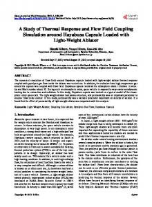
We begin with two illustrations of actual computed solutions. The rst example deals with a pipeline for methane gas. We use a 150 km insulated pipe with a 75 cm internal diameter, carrying gaseous methane. Initially everything is at rest, with a pressure of 8000 kpa and a temperature of 20� C throughout the pipe. We then open the ends of the pipe and drop the outlet pressure to 5500 kpa over 1 minute. Over the next 8 to 16 hours the ow evolves to a steady state. Using 10 km space intervals and 10 minute time steps, we compute the solution after 12 hours. Figure 1 illustrates the resulting pressure, velocity and temperature along the pipe. To t all three variables on one graph, temperature is shown in degrees C, velocity in meters per second, and pressure is in mega-pascals. The second example deals with a pipeline for liquid n-octane. We use a 100 km insulated pipe with a 60 cm internal diameter, carrying liquid n-octane. Initially everything is at rest, with a pressure of 1400 kpa and a temperature of 20�C throughout the pipe. We then apply a ten second pulse of extra pressure at the inlet end. This creates a smooth traveling wave in pressure which propagates down the pipe at the sonic velocity of 1.6 km/sec. The pressure wave has amplitude equal to ten percent of the initial pressure, or 140 kpa. As it travels it excites identical looking pulses in velocity and temperature. Using 1 km space intervals and 5/8 sec. time steps, we compute the solution during the rst 45 seconds. Figure 2 illustrates the resulting pressure at 15, 30 and 45 seconds. We notice a decay in the wave amplitude, due both to friction and to numerical dissipation in the upwinding process. In both examples the friction factor f = 0:014. We now present a table of empirical convergence rates based on these two example scenarios. Table 1 indicates the convergence rates obtained for pressure, velocity and temperature in each of the two scenarios described above. In each case we measured both the L2 and L1 norms of the error in each component, as compared to a reference solution on a much ner mesh. As h was decreased, 4t was decreased proportionately. For the steady state simulation we examined the norm of the error 12 hours after opening the valves. For the small amplitude wave case, we used the norm of the error after 15 seconds. Figure 3 is a log-log plot of the errors as h decreases. It shows sample points for both the L2 and L1 norms of the errors in pressure, velocity and temperature in each of the two scenarios described above. In each case the base ten logarithm of the error is plotted against the base ten logarithm of the number of spatial intervals. These are the sample points used in constructing Table 1. Note that pressure is in pascals, velocity in meters per second, and temperature in degrees Celsius. These units separate the error curves into three bands, with pressure on top, then temperature, and nally velocity. The three bands on the left are for the steady state case; the three on the right are for the small amplitude waves. Each band shows the L2 and 18
L1 norms almost overlapping, because the length of the pipe has been scaled out of the L2 norm.
The table and graph illustrate our empirical observation that even though the rst order nature of piecewise constants appears in the asymptotic convergence rates of the above theorems, in practice we may obtain close to second order convergence rates. This is not too surprising since the pressure and velocity approximations are second order (for � = 1=2), and since isothermal pressure-velocity simulations give good results in many situations. Temperature e�ects generally occur on a much slower time scale than sonic e�ects, so we expect the constant on the rst order error terms to be small relative to typical practical values of h. In fact we see that in the near steady state case, where the temperature varies only slowly, the convergence is indeed approximately second order, at least for pressure, over the parameter range shown. We point out that this range is more than su�cient for practical computations, since the errors shown are well below the error of measurement in the real pipeline. We also see rst order e�ects dominating in the small wave case, since here the temperature changes as sharply and rapidly as pressure and velocity. It is interesting to note the e�ect of temperature on the sonic speed. If E is made extremely large, the e�ect is to force temperature to be essentially constant. This produces a substantial change in the sonic velocity. In the methane pipeline the sonic speed decreases from 415 m/sec in the adiabatic case to 350 m/sec in the isothermal case. In the octane pipeline it decreases from 1630 m/sec to 1312 m/sec. This means that the pulses in Figure 2 would travel about 20% slower if temperature e�ects were omitted, despite the fact that the overall temperature in that example is virtually constant.
7 Remarks and Extensions Remark 1 (Higher Order Methods) We begin by remarking on the choice of
piecewise constants for temperature rather than some higher order representation. We chose piecewise constants for three main reasons. First, higher order methods are harder to analyze. These methods typically involve slope-limiting procedures for which rigorous convergence results do not yet exist even in the scalar equation case. Second, our numerical experiments indicate very good accuracy with piecewise constants in examples where the parameters were chosen to be of engineering interest. Finally higher order methods are harder to code, making them less useful in engineering practice.
Remark 2 (More General Boundary Conditions) Our analysis holds without change for other simple con gurations of boundary conditions such as specifying velocity at each end of the pipe rather than pressure at each end. Luskin[2] treats 19
20.0
15.0
10.0
5.0
0.0 0.0
37.5
75.0
Key: T in deg. C v in m/s p in mpa
Figure 1: Steady State
20
112.5
150.0
200.0
140.0
80.0
20.0
-40.0
-100.0 0.0
25.0
50.0
75.0
Key: Pressure in kpa, p0 = 1400 kpa p(15 sec) - p0 p(30 sec) - p0 p(45 sec) - p0
Figure 2: Small Amplitude Wave
21
100.0
6
4
2
0.5
1
1.5
2
-2
-4
-6
Figure 3: Convergence of the Error
22
2.5
3
very general nonlinear boundary conditions in the non-degenerate case, including ones involving time integrals. We analyze the boundary conditions using a simpli ed version of Luskin's analysis, but we do not treat the complexities he considers. Although it is reasonable to expect the analysis to extend to many of the more complicated boundary conditions he describes, we have not undertaken the task of demonstrating this.
Extension 1 (Non-uniform Time Steps) We remark that the same numerical
method and proofs hold when 4t is allowed to vary in a smooth manner. That is, the three theorems apply when we assume that
j4tn
� ? 4tn+� j � K04t2
+1+
for all n,
and
maxn 4tn+1=2 � K ; 0 minm 4tm+1=2 as both h and 4t go to zero, for the constant K0 of Assumption 3, which is independent of h and 4t.
Extension 2 (Linearizations) We also note that various other linearizations are
possible. We completely linearized the nonlinear terms, but in practice one may drop various small lower order terms. In particular, one need only keep the terms identi ed in the analysis as helping terms in order to achieve numerical stability.
Extension 3 (The Periodic Case) In this section we describe a method for im-
proving a case related to Theorem 1 to yield convergence for any �� given h su�ciently small. In Theorem 2 we accomplished this by weakening the dependence of the problem on temperature. This is not always necessary, as we will show in the following simpli ed case. Suppose the pipeline problem is periodic, so that the pipe forms a closed ring. We use periodic boundary conditions, which eliminates the complexity of the boundary terms in the error analysis. We will introduce a function u~(x; t) which is order h close to the true solution u, but to which the numerically computed solution is h2 close. The periodicity assumption removes technical problems about the smoothness of u~(x; t). This higher order convergence to a comparison function gives the little bit extra needed to extend Theorem 1. In particular, the term C0h2 in (24) becomes C0h4 , which keeps the solutions bounded for any nite time. In the rest of this section we make this more precise by sketching the necessary modi cations to the analysis of Section 8. We assume the reader has already browsed Section 8. In that section the truncation error is de ned in (35) and bounded in (38). Using Taylor's theorem we rewrite it here as
TE = te1 h + te2 h2 ; 23
(21)
where te1 is a smooth function consisting of derivatives of u evaluated where TE is, and te2 consists of integral averages of similar terms. We now de ne a function � by the equation L(�; � ? �?; �?) = te1; (22) with periodic boundary conditions and zero initial data. Then � is smooth by the same assumption we make for u. We now let
u~ = u ? h�: Now we go through the whole analysis of Section 8, changing only the de nition of the discrete interpolant W . Rather than W being the interpolant of u, we let it be the interpolant of u~. Note that discrete derivatives of W are still bounded as they depend on the smooth functions u and �. The matrix L of (66) is now the identity matrix. The entire proof goes through without change, except in (38), where the bound on TE is now second order because the rst order terms have been canceled out by the construction of �. Note that we do not change the induction hypothesis | is still only rst order small since it involves comparing U with u, not u~. However, in (121) the h2 term is now h4 . This carries through the equations of Section 8.5. In addition the h in the H terms is now an h2 . Thus the only real change is in (125) where the right hand side multiplier of h2 becomes h4 . Thus (126) becomes
Cn+1 � h2 (2hr + 4(CJ + (Cn + Cn2)CI hq )tn+1 )1=2 � exp(4(CJ + 2(Cn + Cn2)CI hq )tn):
(23)
Thus C (t) grows like h2 times a xed function of time, and hence can be kept below C� for arbitrarily long times by making h su�ciently small.
24
Table 1: Approximate Convergence Rates steady state small waves
L2
L1
L2
L1
pressure 2.0 velocity 1.1 temperature 1.3
1.9 1.2 1.4
0.9 0.9 1.0
0.9 0.9 0.9
25
8 Error Analysis Note: for an easier to read proof of an important special case, the reader is referred to [1], which treats the linear case of the degenerate problem. Before launching into the details of the proof we give a brief overview. The apriori error bound will be based on using the discrete scheme on U ? W where W is a discrete interpolant of u. The \error equation" for U ? W is a version of the discrete scheme that is linearized about the true solution u. We introduce some notation to get this equation in manageable form; the actual error equation is (47). We then diagonalize the discrete scheme by changing variables; this follows the earlier work of Thome�e and of Luskin. Next we develop an evolution inequality (122) for certain norms of the error, using a discrete l2 inner product of the diagonalized error equation with a test function which is the sum of three terms weighted with carefully chosen powers of h. In developing this evolution inequality there are many terms to estimate; these are summarized in a tableau and estimated one by one. Finally the evolution inequality is used to derive the error bounds. The fact that �� may be nite in Theorem 1 comes from the unusual form of the evolution inequality. In contrast to the usual Gronwall-type evolution inequality, which in the continuous time case looks like
g 0 = Cg + C0h2 ; where C and C0 are constants independent of h, we have an evolution equation of the form pg g 0 (24) g = Cg(1 + h + h2 ) + C0h2; for which solutions can blow up in nite time. In addition, the squared norm of the error, g , corresponds in our case to a non-symmetric energy (K ? H in the notation of section 8.5); we show that the symmetric part dominates the non-symmetric part.
8.1 The Error Equation We consider the degenerate case of equation (8), with the numerical method given by equation (17). Recall that the non-degenerate case is a simpli cation of these equations.
Convention 1 In what follows we let C be a generic constant whose value in any particular equation depends upon various Sobolev norms of A, �, F , u, and the constant K0 of Assumption 3, but which is otherwise independent of the discretization parameters h, 4t and �. 26
Throughout this section assumptions 1 and 3 hold. In what follows we take � = 3 as in the thermal pipeline equations, but the proof works in general. The symbol d will be used to distinguish discrete operators from continuous ones. Let us de ne two operators L and Ld as follows:
Lk (a; b; c) = akt + Akj (c)axj + (Akj;i(c)cxj ? Fk;i(c))bi + �k ((�(c)a )x ? �x(c)a + (�;i(c)c bi )x ? (�;i(c)bi)xc ) ;
(25)
Ldk (a; b; c) = @tak + Akj (c)@xaj + (Akj;i(c)@xcj ? Fk;i(c))bi + �k (@x (�(c)a ) ? a @x �(c) + @x (�;i(c)c bi ) ? c @x (�;i(c)bi)) :
(26)
3
3
3
3
3
and 3
3
3
3
3
Then we may re-write (14) and (17) in a more compact form: the true solution u satis es the equation
L(u; u ? u? ; u?) + Quad(u ? u? ; u?) = F (u? );
(27)
while at Q^ our discrete solution U satis es
Ld(U; U ? U ?; U ?) = F (U ? ):
(28)
Recall that U is piecewise linear in time, and each Ukn is piecewise linear in space, except U3n , which is discontinuous piecewise constant, upwinded by �(U n?1). It will now be useful to introduce a discrete interpolant W of u. Such a function is de ned in the same discrete space as U . Therefore U ? W is also in the discrete space, and thus is easier to analyze than U ? u. We de ne W by Wkn (xj ) = unk (xj ) for k < 3, and W3n (xj +1=2 ) = un3 (xj +1=2 ), with W3n at the knots upwinded by �(U n?1 ). We now de ne the total error = u ? U; the discrete error
� = W ? U; and the approximation error
e = u ? W: Under reasonable conditions we know that e is small; it thus su�ces to show that � is small. Consider the quantity
� = Ld (�; � ? � ? ; u?) over Q^: 27
(29)
From (27) and (28) we see that
where
� = Ld (W; W ? W ? ; u? ) ? L(u; u ? u? ; u?) + L^d (U; U ? U ? ; U ? ; u? ) ? Quad(u ? u? ; u?) + F (u? ) ? F (U ? );
(30)
L^d (a; b; c; d) = Ld (a; b; c) ? Ld (a; b; d);
(31)
Ld (a + a0; b + b0; c) = Ld (a; b; c) + Ld(a0; b0; c):
(32)
and we used the fact that
It is also true that L^d (U; U ? U ? ; U ?; u?) = L^d(W; W ? W ?; U ?; u?) ? L^d (�; � ? � ?; U ?; u?): (33) Now if U ? u turns out to be small, the L^d (� ) terms will just be small perturbations to the Ld (� ) terms; hence we nally write the discrete error equation Ld(�; � ? � ? ; u?) + L^d (�; � ? � ? ; U ?; u?) = TE + NL; (34) where the truncation error is
TE = Ld(W; W ? W ? ; u) ? L(u; u ? u? ; u?) ? Quad(u ? u? ; u?) and the remaining nonlinear terms are NL = L^d (W; W ? W ? ; U; u?) + F (u? ) ? F (U ? ):
(35) (36)
Thus the discrete error � satis es a perturbed version of the equation satis ed by U . The perturbations vanish in the linear case; the � equation also has truncation
error as its main inhomogeneous term. Recall that P is de ned by (13) or (18). To make the expansion of (34) manageable, we introduce the following generic objects, which may be functions, vectors, matrices, three tensors or four tensors, and are all smooth functions of their various arguments.
M = M (u; ux; and any other derivatives as needed): M� = M� ( ; u; ux; : : :): M� p = M� p(P ; u; ux; : : :): For instance, we can write u + @x u = M , and U = M ? , and @x U = M ? @x . 28
We can write the identity
f (U ) ? f (u) = (Ui ? ui) as
Z 0
1
f;i(u + s(U ? u))ds
f (U ) ? f (u) = M� :
Other useful identities are f (PU ) ? f (Pu) = M� p P ; f (U )U ? f (u)u = M� ; f (U )@xU ? f (u)@x u = M� + M@x + M (@x ) ; f (U )P@x U ? f (u)P@x u = M� + MP@x + M� (P@x ) ; f (PU )P@xU ? f (Pu)P@x u = M� p P + MP@x + M� p (P@x )P : We also note the discrete product rule @x (fg) = fc @x g + gc @x f; and chain rule @x(f (g)) = I (f 0(g))@xg; where Z1 0 I (f (g)) = f 0(g(x?) + s(g(x+) ? g(x?)))ds: 0 Finally, we de ne M� = M� ; and M� p = M� p P : Convention 2 The point of using the M notation is to simplify dealing with the nonlinear terms arising from the di�erences U ? ? u? . To avoid putting minus sign superscripts on everything, we declare that henceforth M� , M� p , M� and M� p should be interpreted as involving ? rather than . Let us write Q3 for the third column of the matrix Q = I ? P . Using this notation, we nd that the truncation error is TE = ?Quad(u ? u; u? ) + (@tW ? ut) + MP (@x W ? ux ) + M (W ? u) + M (W ? W ? ? (u ? u? )) + M (u ? u? )(@xu? ? u?x ) ? + Q3 @x (�(u?)W3 ) ? (�(u?)u3 )x ? W3@x �(u? ) + u3 �x (u? ) + @x (�;i(u? )u?3 (Wi ? Wi? )) ? (�;i(u? )u?3 (ui ? u? ))x � (37) ? u?3 (@x(�;i(u?)(Wi ? Wi? )) ? (�;i(u?)(ui ? u?i ))x) : 29
These are mainly the usual truncation terms for collocation and can be shown to be small by standard approximation theory methods or simple Taylor expansions; we nd that for some C independent of h, 4t and �, (38) jTEjm2 � C (h + 4t2 + (� ? 12 )4t); 8t 2 P^t: In the non-degenerate case, the h becomes an h2 , since there are no piecewise constants. In both cases, jP (TEn+1+� ? TEn+� )jm2 � C (h4t + 4t2 ): (39) We pause to remark that
@x M = M; � x ; @x M� = M� + M@ and @x M� p = M� p + M� p P@x : We now turn to the terms in (34) containing L^d . � � + Mb � x a + Ma L^d (a; b; U ?; u?) = MP@ + (M� �+ MP@x ? + M� (P@x ? ) ? b) � ) + Q3 @x ((�(U ?) ? �(u? ))a3) + a3 @x (�(U ?) ? �(u?)) + @x (MPb � � ) + ?3 @x ((M + M� )Pb) ; (40) + M@x (MPb where we used the expansion U3@x(�;i (U )bi) ? u3@x (�;i(u)bi) = U3@x ((�;i(U ) ? �;i (u))bi) + (U3 ? u3 )@x (�;i(u)bi) � ) + 3 @x ((M + M� )Pb): = M@x (MPb This simpli es to � x a + Ma � + Mb � + (M + M� )(P@x ? )b L^d(a; b; U ?; u) = MP@ ? + Q3 @x ((�(U ?) ? �(u?))a3 ) ? a3@x (�(U ?) ? �(u? )) � ) + ?3 @x ((M + M� )Pb)� : (41) + M@x (MPb Before deriving the analogous expression for Ld , we note that u? is smooth, so we can safely undo the abx = (ab)x ? ax b transformation used in (26). In particular, @x (�;i(u? )u?3 bi) ? u?3 @x(�;i(u? )bi) = (@x u?3 )(�;i(u? )bi );c + (u?3;c ? u?3 )@x(�;i (u? )bi) = MPb + h2 M@x (MPb): (42) 30
Thus
Ld(a; b; u?�) = @ta + A? P@xa + Ma +�Mb + Q3 @x (�? a3 ) + h2 M@x (MPb) ;
(43)
where we have written A? and �? for A(u? ) and �(u? ), rather than M , for future convenience. We can now expand (34) in a reasonably simple manner:
@t � + A? P@x � + M� + M (� ? � ? ) ? � + Q3 @x (�? �3) + M@x (MP (� ? � ? )) � + M� (� ? � ? ) � x � + M� + MP@ + (M�+ M� )(P@x ? )(� ? � ? ) � (� ? � ? )) + Q3 @x ((�(U ?) ? �? )�3) + �3@x M� p + M@x (MP � + ?3 @x ((M + M� )P (� ? � ? )) = TE + NL: We note that in (36), there are still � terms: F (u?) ? F (U ?) = M� 4t + M� 4t2 + M� 4t@t �;
(44) (45)
where we used u ? U = e + � and
F (u)(u ? u?) ? F (U )(U ? U ?) = (F (u) ? F (U ))(u ? u? ) + F (U )[(u ? u? ) ? (U ? U ? )]: We will put this @t � term on the left hand side, below. Since W depends only on u, we have L^d (W; W ? W ? ; U ?; u?) = M� + (M + M� )(P@x ? )4t ? + Q3 @x ((�(U ?) ? �? )W3 ) ? W3@x (�(U ? ) ? �? ) � 4t) + ?3 @x ((M + M� )4t)� : + M@x (M
(46)
Thus (44) becomes, via (31, 32, 27, 29, 22):
LHS = TE + IND; where the new terms are IND = M��+ M� 4t2 + (M + M� )(P@x ? )4t � 4t) + ?3 @x ((M + M� )4t)� ; + Q3 M� p + hM@x (P ? ) + M@x (M 31
(47)
(48)
and
LHS = @t� + A?P@x � + M� + (M + M� )4t@t � ? � x � + M� � � � + MP@ � ? + M2 4t@t� + (M + M )(P@x )?4t@t� ? + Q3 @x (� �3) + h M@x (MP 4t@t � ) + @x ((�(U ) ? � )�3 ) � 4t@t � ) + ?3 @x ((M + M� )P 4t@t � )� : + �3 @x M� p + M@x (MP
(49)
This simpli es to
LHS = @t� + (M + M� + M� + (M + M� )(P@x ? ))4t@t � � x � + (M + M� )� + A? �P@x � + MP@ + Q3 @x (�? �3) + @x ((�(U ? ) ? �? )�3) + �3 @x M� p � x ((M + M� )P@t � 4t) + M@x ((h2 M + M� )P@t � 4t)� : + M@
(50)
In this form one can see the linear terms and how they are perturbed by small nonlinear terms, subject to some induction hypotheses which we formalize later, to the e�ect that ? and P@x ? are small, whence M� and @x M� p are also small. To facilitate the diagonalization process described below, we make one more adjustment to this equation. We recall that A = AP and A� = AP + �Q, and that A? and �? depend only on u? and hence are smooth in space. Thus we may write
A? P@x � + Q3 @x (�?�3 ) = @x(A�? � ) + MP�;c + h2 MP@x �:
(51)
8.2 Diagonalization Before proceeding further with the error analysis of (47), we must rst change variables in order to diagonalize the matrix A� in (51). This is a standard step, also used by Luskin; we remark that it is done only in the proof, not in the numerical computation. From here on in we need to distinguish two parallel threads in the proof, one for the degenerate case and one for the non-degenerate case. In the non-degenerate case P = I , Q = 0, and there are no piecewise constants to keep track of, which simpli es matters to the point where we can prove an H 1 estimate. In the degenerate case we only get L2 convergence. As much as possible, we will do the two cases together. The diagonalization is a bit messy, but using our M notation it is not too hard to write it all out. We de ne two new matrices S and R, which will be smooth functions of x and t. We de ne S to be a bounded matrix of column eigenvectors of A�, and R = S ?1 . By assumption in Section 4 the matrices R and S are smooth and bounded functions 32
of u. We nd that in the degenerate case, both S and R can be selected to have the form
1 0 � � 0 C BB BB � � 0 CCC : A @ � � 1
Thus S = SP + Q, and R = RP + Q. � = diag(�1; �2; �). By hypothesis, � is a bounded function We de ne � = RAS of u. Also for any scalar function f , we note that RQf = Qf . We now de ne, for all x and t,
!(x; t) = R(x; t)� (x; t):
(52)
We note that P! = MP� and P� = MP! . Although � is piecewise linear in time, ! is not. However,
!n+� = Rn+� � n+� = Rn+� (�� n+1 + (1 ? �)� n ); since � is piecewise linear time; hence using ! = M� and � = M! we see ! n+� = M! n+1 + M! n , or more compactly ! = M! + + M! ? in P^t for all x: (53) We compute the following transformations over Q^ , writing S +1=2 = S (tn+1=2 ):
@t � = @t(S!) = S ;c @t! + (@tS )! ;c = S +1=2@t ! + 4t2 MP@t ! + MP! ;c ;
(54)
in which we note that any derivative of R or S introduces a factor of P , and similarly, @x (A�? � ) = S +1=2@x (�? !) + 4tMP@x ! + MP!;c ; (55)
P@x � = MP@x ! + MP!;c ; and
(56)
� = S! = S +1=2! + 4tMP!: (57) We left multiply equation (47) by R+1=2 to create a diagonalized error equation, obtaining
R+1=2 � LHS = @t ! + 4t2 MP@t ! + MP! ;c + (M + M� + M� + (M + M� )(P@x ? ))4t(M@t ! + MP! ;c ) + @x (�? ! ) + (4tM + h2 M + M� )P@x ! 33
+ (M �+ M� )P!;c + (M + M� )! + Q3 @x ((�(U ?) ? �? )�3) + M!@x M� p � x ((M + M� )P@t � 4t) + M@x ((h2M + M� )P@t � 4t)� + M@ = M � TE + M � IND:
(58)
Notice that there is essentially no change in the right hand side terms. We write DLHS for the diagonalized left hand side of this equation. We simplify it, and also combine the term Q3 (@x((�(U ?) ? �? )P�3 )) with the �? matrix, which simply makes the (3,3) entry of �? depend on PU ? rather than Pu? . This is exactly what we need to handle the upwinding terms, since the upwinding is based on PU ? , rather than Pu? . Henceforth, �? will mean this modi ed version. This leaves us with DLHS = @t ! + (M + M� + M� + (M + M� )(P@x ? ))4t@t! + @x(�? !) + (4tM + h2 M + M� )P@x ! + (M + M� )! + (M + (M� + M� + (M + M� )(P@x ? ))4t)MP! ;c + (M + M� )P!;c � + Q3 @x (M� p P! ) + M!@x M� p � x ((M + M� )P@t � 4t) + M@x ((h2M + M� )P@t � 4t)� : (59) + M@ We de ne
�t = 4t(M + M� + M� + (M + M� )P@x ? );
and
� �x = 4tM + h2M + M: Since � is piecewise linear in time, and P� is in space, we can write
(60) (61)
P! ;c = P! + M 4tP@t !;
(62)
P!;c = P! + MhP@x !:
(63)
�z = M� + 4t(M� + (M + M� )P@x ? )P;
(64)
and Thus we also de ne whence (59) simpli es to
B D A A0 B0 ? DLHS =@t! + �t@t! + @x (� !) + �xP@x ! + (M + �z )! 34
0 G BB �F + Q @@x (M p P! ) + M!@x M� p 3
1
H C � � + M@x ((M + M )P@t � 4t) + M@x ((h2M + M� )P@t � 4t)C A C
= M � TE + M � IND = � ;
(65)
where we label each of the nine terms with a letter for future convenience and lump the two right hand side terms together as �. We have written the general case here; recall that in the non-degenerate case, the only change is that Q becomes zero. Equation (65) looks very much like the corresponding error equation in the linear case, except for the addition of terms which we hope to show are small, by induction. Note that (65) holds at every point of Q^ . Let L = diag(l1; l2; l3); (66) be a diagonal matrix where and where
lk (x; t) = g(�k(0; t))(1 ? Ex ) + g(?�k(E; t)) Ex ; for k = 1; 2,
(67)
l3(x; t) = �0 ;
(68)
8 > < 1 if � < 0; g(�) = > : � if � � 0:
(69)
0
Here �0 is a small positive constant to be chosen later, independent of h and 4t. Note that each lk is constant in time for each xed x since the signs of �1 and �2 never change. Each lk is also linear in space. Let us now de ne r by
8 > > < 1 in the context of Theorem 1, r = > 1=2 in the context of Theorem 2, or > : 0 in the context of Theorem 3. 35
We now de ne, at each point in Q^ , the test function we will use for the energy analysis: 3 2 1 (70) ' =L! + �hr P@t ! + hr PL@t @x (�!); where we leave unspeci ed two non-negative parameters � and , which will be determined later and will be independent of h and 4t.
8.3 The 27 Product Terms
We form the vector inner product of both sides of the equation (65) with ', producing another equation involving 27 product terms which must be considered individually. The following chart summarizes the situation.
? 1 2 3
j A + ? j L j L j R
A0 B B 0 C D F G H
? ? ? ? ? ? ? ?
R R R R R R R R R R R R R 0 0 0 R L R R R 0 0 0
Since P � Q = 0, 6 terms vanish automatically. Three other terms marked with an \L" are \helping" or \left hand side terms"; the other 18 are right hand side terms. The analysis of each term proceeds just as in the linear case. The product equation DLHS � ' = � � ' holds at every point of Q^; for each time level tn+� in P^t we multiply by h and sum over all x's in P^x , thus forming the discrete spatial midpoint-based m2 norm. Some right hand side terms will be hidden by direct subtraction; later we will use a time-induction form of Gronwall's inequality to handle the rest. For each right hand side term we give an upper bound for the sum over P^x. For the three terms marked L, we give a positive lower bound instead. The bounds may not be obvious at rst, but they follow in straightforward ways from the properties of the objects involved, in particular from knowing that � is piecewise linear in time and either piecewise linear or piecewise constant in space. We begin with the three \helping terms" A ? 1, A ? 2, and B ? 3.
8.3.1 A-1 We write the steps out in some detail for this rst left-hand side term: @t! � L! � 21 @t(L! � !) + (� ? 21 )4t�0 (@t!)2 ? C ((! ?)2 + (! +)2); 36
(71)
since L is constant in time, linear in x and bounded below by the positive constant �0 . The above equation holds at each point of Q^ , hence for each point in P^t , X @t! � L!h � �20 @tj!j2m2 + (� ? 21 )�04tj@t !j2m2 ? C (j! ?j2m2 + j! +j2m2 ): P^ x
Here C is a generic constant independent of h, 4t; it can depend on �0 and as always, on norms of u.
8.3.2 A-2
X P
^x
8.3.3 B-3 X P^x
@t! � �hr P@t !h � �hr jP@t!j2m2 :
(72)
@x(�? !) � hr PL@t@x (�!)h
� hr
��
@ j P@ (�! )j2m2 + (� ? 1 )�04tjP@t @x (�! )j2m2 t x 2 2 0
� ? C (jP@x(�?!?)jm2 + jP@x (� ! )jm2 ) ; +
2
+
2
(73)
plus a right hand side term of the same form as B 0 ? 3 which comes from writing �? = � + (�? ? �). We ignore this term here since it will be treated automatically under B 0 ? 3. We now turn to giving upper bounds for right hand side terms. We do some easy terms rst.
8.3.4 D-1
X P
^x
8.3.5 B-2 X P^x
8.3.6 D-2 X
(M + �z )! � L!h � C (1 + j�z jm1 )j! j2m2 : r
r ? 2 2 @x (�? !) � �hr P@t!h � �h 64 jP@t ! jm2 + �h C jP@x (� ! )jm2 : r
(M + �z )! � �hr P@t ! h � �h jP@t ! j2m2 + �hr C (1 + j�z jm1 )2j! j2m2 : 64 P^x 37
(74)
(75)
(76)
8.3.7 C-1 We now rewrite
� 2 + MhP@x ? : � = Mh + M� ? + Mh
We now nd it useful to expand this as � 2 + M! � + M� 4t@t ! + MhP@x ! + Mh2 P@t @x !: � = Mh + Mh
(77)
We use this in the C terms.
X P^x
8.3.8 C-2 X P^x
� � L!h � C (h2 + j!j2m2 + h2 j@t !j2m2 + h2 jP@x !j2m2 + h4 jP@t @x !j2m2 ):
(78)
r
2 2+r � � �hr P@t!h � �h 64 jP@t ! jm2 + Ch
+ �hr C (j! j2m2 + h2 j@t ! j2m2 + h2 jP@x ! j2m2 + h4 jP@t @x ! j2m2 ):
(79)
8.3.9 B-1 This term contains helping terms as well as right hand side terms, so we give a lower bound.
X P^x
@x (�? !) � L!h � 3 1X 2 2 ? 2 x=E 2 k=1(�k lk !k )jx=0 ? C j!k jl2 ? ChjP@x ! jm2 :
(80)
Note that j!k j2l2 � C (j!k j2m2 + h2 jP@x !k j2m2 ). In the non-degenerate case the rst order term in h becomes second order, so an L2 estimate with r = 2 is possible. In the degenerate case, the presence of the rst order term requires r � 1, thus giving a slightly better than L2 result. This analysis of the B ? 1 term arises from detailed consideration of the form of products of combinations of piecewise linear and piecewise constant functions and their derivatives.
38
8.3.10 A-3
X P^x
@t ! � hr PL@t@x (�!)h :
We note that !3 does not appear in this term, so only piecewise linear functions need be considered. We write
a b @t@x(�!) =@x ((@t�)! ;c) + @x (�;c@t !) : From (a) we have
hr
X P^x
P^x
@t! � PL@x ((@t�)! ;c )h �
�hr jP@ !j2 + C hr jP@ ! ;c j2 ; x m2 64 t m2
while from (b), we get
hr
X
@t! � PL@x (�;c @t!)h �
2 hr X (�;cklk (@t !k )2 )jxx==0E ? hr C1jP@t ! j2l2 : 2
We then bound
(81)
k=1
(82)
hr C1jP@t !j2l2 � hr C1jP@t !j2m2 + hr Ch2 jP@t@x !j2m2 : For su�ciently small relative to �, the rst term hides, and since h � 4t the second term is bounded by
hr C1(jP@x!+ j2m2 + jP@x !?j2m2 ): The spatial boundary terms in (80) and (82) turn out to give non-negative helping terms, provided �0 is chosen su�ciently small relative to certain O(1) constants depending only on u. This follows from the form of L, which is carefully chosen based on a trick used by Luskin and pioneered by Thome�e. Essentially it works as follows. Consider the term in (80) at x = 0; by hypothesis on the signs of the �i , this is ?�0j�1j!12 + j�2j!22 ? �0�!32: If � > 0, then �3 (0) = 0 by choice of boundary conditions. Since j�j � j�1j and j�j � j�2j, we can bound this term below by ?�0(j�1j + j�j)!12 + (j�2j ? j�j)!22: 39
This is positive for �0 su�ciently small, given physically realizable boundary conditions. That is, we don't want !2 (0) to vanish unless !1 (0) also vanishes. For instance, if the boundary conditions are that we specify the pressure at both ends of the pipe, then �1 (0) = �1 (E ) = 0, whence !1 (0) and !2 (0) are proportional by a constant depending on A(u) and not on h or 4t. Similar arguments apply at x = E and to the @t ! terms from (82).
8.3.11 C-3
� terms of � and bound the rest directly. We \sum by parts in time" on the Mh + M!
X P^x
� � hr PL@t@x (�!)h � hr?1 (h2 j@t!j2m2 + h2 jP@x!j2m2 + h4jP@t @x !j2m2 + Ch4 ) 2 r +1 2 + C X h jP@�t@x!jm2r + (Mh + M! ) � h PL@t @x (�! )h: P^x
(83)
We recall a formula for summation by parts in time at t = tn+� : an+� @ b = 1 an+� (b+ ? b?) = 1 (an+� b+ ? an?1+� b?) ? 1 (an+� ? an?1+� )b+: t
4t
4t
4t
Thus we write � ) � hr PL@t @x (�! )h = (Mh + M!
X P^x
hr X((Mh + M! � ) � PL@x (�+! + ) ? (Mh + M! � )n?1+� � PL@x (�? ! ? ))h 4t ^ Px X � ) ? (Mh + M! � )n?1+� ) � PL@x (�+ ! + )h: (84) ? hr?1 ((Mh + M! P^x
We can bound the second sum by r
2 2+r r ?2 2 C hr jP@x (�+ !+)j2m2 + �h 64 j@t ! jm2 + Ch + C h j@t jm1 j! jm2 :
8.3.12 D-3 As in C ? 3, we sum by parts on the M! term, which we need not repeat here. We
write �z = M� + C�t , and again sum by parts on the M� term, while on the �t term we use the bound 40
X P^x
�t! � hr PL@t @x (�!)h � C j�tj2m1 h?3=2j!j2m2 + 2 h2r+3=2jP@t@x!j2m2 :
(85)
hr X(M! � � PL@x (�+ ! + ) ? (M! � )n?1+� � PL@x (�? ! ? ))h 4t ^ Px X � � )n?1+� ) � PL@x (�+! + )h: ? (M! ? hr?1 (M!
(86)
The summation by parts on the M� term is X� M! � hr PL@t@x (�!)h = P^x
P
^x
We can bound the second sum by r 2 � 2 C hr jP@x (�+ ! + )j2m2 + �h 64 jM jm1 j@t ! jm2 + hr (j@t ? j2m1 + j ? j2m1 )j! j2m2 :
8.3.13 A0-1
X P
^x
8.3.14 A0-2
�t@t! � L!h � � j� j2 1 j@ !j2 : C j!j2m2 + 64 t m t m2
X P^x
(87)
�t @t! � �hr P@t !h � �hr j�t jm1 j@t!j2m2 :
(88)
8.3.15 A0-3 X P^x
�t@t ! � hr PL@t @x (�!)h �
j�tjm1 hr? = j@t!jm2 + Chr 2
3 2
2
41
=
+3 2
jP@t @x(�!)jm2 : 2
(89)
8.3.16 B0-1
X P
^x
�x P@x ! � L!h � j!j2m2 + j�x j2m1 jP@x !j2m2 :
8.3.17 B0-2 X P
^x
r
2 r 2 2 �x P@x ! � �hr P@t !h � �h 64 jP@t ! jm2 + C�h j�x jm1 jP@x ! jm2 :
(90)
(91)
8.3.18 B0-3 X P^x
�x P@x ! � hr PL@t @x(�!)h
� hr jP@x!jm2 + j�xjm1 hr jP@t@x(�!)jm2 : 2
2
2
2
(92)
In the non-degenerate case, we are done. In the degenerate case we still have to consider F ? 1, G ? 1, and H ? 1.
8.3.19 F-1 We note that Hence
X P^x
@x M� p = (@x M� p )P ?;c + M� p;c P@x ? :
@x (M� pP!)�0!3 h =
X P^x
X ((@xM� p )P ?;c + M� p;c P@x ? )!;c �0!3 h + M� pP@x !�0 !3 h
� C (j!jl2 + jM� pj2m1 jP@x !j2m2 ):
P^x
2
(93)
Note that M� p is h3=4 in m1 , and j!3 jl2 = j!3 jm2 , so this is ne.
8.3.20 G-1
X P^x
M!@x M� p�0 !3 h � C (jP ? jm1 + jP@x ? jm1 )j!j2m2 :
42
(94)
8.3.21 H-1 X� � P^x
�
M@x((M + M� )P@t� 4t) + M@x((h2 M + M� )P@t � 4t) �0!3 h �
C j!j2m2 + j ?jm1 4t2 j@t @x P!j2m2 + j ?jm1 (1 + jP@x ? jm1 )4t2 jP@t � j2m2 + j@x ? jm1 4t2 jP@t � j2m2 : (95)
We also write j@x ? jm1 4t � j ? jl1 :
8.4 The Induction Hypothesis We are nally in a position to collect the 27 terms. Before we write it all out, we specify that �0 be taken small enough (based on order one constants) to make the B ? 1 and A ? 3 boundary terms non-negative, as described above, and we then take � to be a small fraction of �0 , based on some other order one constants, and then take small relative to � again based on order one constants, and nally require h and 4t to be su�ciently small with respect to these other constants. A number of right hand side terms now can be directly subtracted o� from left hand side terms. These are terms with a small multiplier on them, usually written as 641 above. However, other terms which we would like to hide by subtraction involve factors such as j�t jm1 . We must now specify an induction hypothesis that makes these factors su�ciently small. For example, in the bound for term D ? 3 above there is a term �hr jM� j2 1 j@ !j2 : 64 m t m2 To be able to subtract this from the A ? 1 term (� ? 12 )�0 4tj@t ! j2m2 ; we need to assume that there are positive constants C� and � independent of h such that � �+(1?r)=2 : j ? jm1 � Ch In the non-degenerate case we can subtract it from the A ? 2 term instead, so we need only that � �: j ? jm1 � Ch In either case, the inclusion of the � > 0 means that for h su�ciently small, the term can indeed be subtracted. There are other right hand side terms which do not hide by subtraction. We wish to treat these by a Gronwall-like time induction. Once again we will need 43
induction hypotheses to keep the nonlinear terms su�ciently small. For example, in the bound for term D ? 1 above there is a term
C j�z jm1 j!j2m2 : To make this be only a small correction to terms like
C j!j2m2 ;
which arise in A ? 1, we need to assume there are positive constants C� and q independent of h such that � q: j�z jm1 � Ch
It may happen that the best we can get is q = 0; in this case the convergence estimate may only hold for a xed nite time regardless of decreasing h. In order to state the induction hypothesis we begin with a couple de nitions. Let
K n = j! nj2m2 + hr jP@x (�n!n )j2m2 ;
(96)
J n = hr jP@t! n?1+� j2m2 + hj@t !n?1+� j2m2 + hr+1 jP@t @x!n?1+� j2m2 : Now let C� be a constant independent of h, to be speci ed later.
(97)
and
Assumption 4 (The Induction Hypothesis) We assume that at time tn � , there is a non-negative number Cn � C� such that Cn? � Cn and K n + hJ n � (Cnh) : (98) +
1
2
The induction hypothesis implies
j� jm2 + hr= jP@x� jm2 � Ch; 2
(99)
where the C here is proportional to Cn . Standard approximation theory facts like 1 1 ? j� jm1 � Ch 2 j� jm2 and j� jL1 � C (j� jL2 j� jH 1 ) 2 allow us to deduce the following additional bounds:
j� jm1 jP� jm1 j jm2 j jm1 jP jm1
� � � � � 44
Ch1=2; Ch1?r=4; Ch; Ch1=2; Ch1?r=4;
(100) (101) (102) (103) (104)
jP@x jm2 jP@x jm1 j�tjm2 j�tjm1 j�xjm2 j�xjm1 j�z jm2 j�z jm1
� � � � � � � �
Ch1?r=2; Ch(1?r)=2; Ch; Ch; Ch; Ch1=2; Ch; Ch1=2:
(105) (106) (107) (108) (109) (110) (111) (112)
In the non-degenerate case we get the improved bounds
j�xjm1 � Ch ?r= ; 1
and
4
j�z jm1 � Ch ?r= : 1
4
The induction hypothesis also implies (113) hr jP@t ? j2m2 + hj@t ? j2m2 + hr+1 jP@t @x ? j2m2 � C 2h; from which we also get the bounds (114) j@t jm2 � Ch0; ? 1=2 (115) j@t jm1 � Ch ; (1?r )=2 jP@t jm2 � Ch ; (116) 1=4?r=2 jP@t jm1 � Ch : (117) In the non-degenerate case these improve to (118) j@t jm2 � Ch(1?r)=2; 1=4?r=2 j@t jm1 � Ch : (119) In all of these induction related bounds, the C is proportional to Cn . We point out that the above relations imply analogous bounds on the various M� constructs.
8.5 The Gronwall Induction
Let us now de ne q by
8 > > < 0 in the context of Theorem 1, q = > 1=4 in the context of Theorem 2, or > : 1=2 in the context of Theorem 3. 45
Returning to the error equation, we now multiply by 24t, subtract the terms that can now be subtracted based on the induction hypothesis, and are left with the inequality
Gl � Gr ;
where
Gl = �0 (j!+ j2m2 ? j! ?j2m2 ) + (� ? 12 )�04t2 j@t !j2m2 + �hr+1 jP@t ! j2m2 + hr �0 (jP@x (�+! + )j2m2 ? jP@x (�?! ? )j2m2 ) + hr (� ? 21 )�0 4t2 jP@t @x (�! )j2m2 : (120)
The reader can check that the above induction hypothesis allows us to write that for some constants CI and CJ independent of h,
Gr = (C� J + CI (Cn + Cn2)hq )4t� � j!? j2m2 + j!+j2m2 + hr (jP@x(�?!?)j2m2 + jP@x(�+!+)j2m2 ) + h2 X� � )n+� � PL@x (�+! + ) � + M! + hr (Mh + M! P^x
� )n? � + M! ?(Mh + M!
� � PL@
1+
?!? )
x (�
�
h:
(121)
We must now investigate how Cn grows with n. We de ne X� � )n+� � PL@x (�+ ! + )� h: � + M! H n+1 = hr (Mh + M! P^x
Then we have
K n+1 + hJ n+1 ? H n+1 � K n ? H n + (CJ + (Cn + Cn2)CI hq )4t(K n+1 + K n + h2 ):
(122)
Summing in time many terms telescope, yielding
K n+1 ? H n+1 + hJ n+1 � n X K 0 ? H 0 + (CJ + (Cn + Cn2)CI hq )nh3 + 2K k (CJ + 2(Ck + Ck2)CI hq )4t + h(CJ + 2(Cn + Cn
2
k=0
)CI hq )K n+1 :
(123)
Now by the correct choice of initial conditions, namely U 0 = W 0 , the induction hypothesis is satis ed at the initial time level with C0 = 0. Similarly K 0 = H 0 = 0. 46
Also note that even when q = 0, for h su�ciently small h(CJ + 2(Cn + Cn2 )CI hq ) < 1=2. Now,
jH n j � = hr jPL@x(� ! )jm2 +1
3 2
+
+
2
+ 1=2hr (Ch2 + C (1 + C�2h)(j! + j2m2 + 4t2 j@t ! j2m2 ));
Thus for su�ciently small with respect 1=(C�2h), H n+1 < K n+1 =2 + h2+r . This is a harmless extra constraint on since below we will be keeping C�2hq bounded. Thus,
K n+1 + hJ n+1 � 4(CJ + (Cn + Cn2)CI hq )tn+1 h2 + 2h2+r n X + 8 K k (CJ + 2(Ck + Ck2 )CI hq )4t: k=0
(124)
So by the usual discrete Gronwall inequality,
K n+1 + hJ n+1 � h2 � (2hr + 4(CJ + (Cn + Cn2)CI hq )tn+1 ) � exp(8(CJ + 2(Cn + Cn2)CI hq )tn ):
(125)
Hence we determine that at the next time level the induction hypothesis continues to hold, with
Cn+1 � (2hr + 4(CJ + (Cn + Cn2)CI hq )tn+1 )1=2 � exp(4(CJ + 2(Cn + Cn2)CI hq )tn):
(126)
However, this is only true as long as Cn+1 � C�. Thinking of Cn as de ning a function C (t) by n corresponding to tn , we may ask \for what t does C (t) rst exceed the stated upper bound?" This time will be the �� of the theorems. Let CG = 4CJ + 2hr + 8CI (C� + C�2)hq . To see how C (t) grows, we note that Cn < C� implies C (t) � (CGt)1=2 exp(CG t): Thus given any xed values of C� and h, C (t) grows roughly exponentially with time, and will eventually exceed C�. If q > 0, then we can increase C� yet decrease h so as to leave CG unchanged; this allows us to make �� as large as desired.
47
Acknowledgment: I would like to thank my thesis advisor, Professor Todd
Dupont, for suggesting this problem and for many hours of helpful advice, and my wife Mary Jo and my parents for all their love and support. This work was supported in part by a National Science Foundation Graduate Fellowship.
References [1] P. T. Keenan, An error estimate for a new scheme for the general variable coe�cient linearized thermal pipeline equations, Tech. Report 90{20, Department of Computer Science, University of Chicago, 1990. [2] M. Luskin, An approximation procedure for nonsymmetric, nonlinear hyperbolic systems with integral boundary conditions, SIAM J. Numer. Anal., 16 (1979), pp. 145{164. [3] M. Luskin and T. Blake, The existence of a global weak solution to the nonlinear waterhammer problem, Comm. Pure Appl. Math, 35 (1982), pp. 697{735. [4] V. Thom�ee, A stable di�erence scheme for the mixed boundary problem for a hyperbolic, rst order system in two dimensions, J. Soc. Indust. Appl. Math., 10 (1962), pp. 229{245. [5] E. B. Wylie and V. Streeter, Fluid Transients, McGraw Hill, New York, 1978.
48