Journal of Mechanical Science and Technology 28 (8) (2014) 3387~3394 www.springerlink.com/content/1738-494x
DOI 10.1007/s12206-014-0751-9
Thermo-hydrodynamics of closed loop pulsating heat pipe: an experimental study† Pramod R. Pachghare1,* and Ashish M. Mahalle2 1
Department of Mechanical Engineering, Government College of Engineering, Amravati, 444-604, India 2 Department of General Engineering, Laxminarayan Institute of Technology, Nagpur, 444-001, India (Manuscript Received September 1, 2013; Revised February 27, 2014; Accepted March 21, 2014)
----------------------------------------------------------------------------------------------------------------------------------------------------------------------------------------------------------------------------------------------------------------------------------------------
Abstract The experimental result on the thermal performance of closed loop pulsating heat pipe (CLPHP) is presented. The CLPHP is made of copper capillary tubes, having inner and outer diameters of 2.0 mm and 3.6 mm respectively. The working fluids employed are water, ethanol, methanol and acetone also binary mixture (1:1 by volume) of water-ethanol, water-methanol and water-acetone. For all experimentations, filling ratio (FR) 50%, two-turns and vertical bottom heat mode position was maintained. The lengths of evaporator, condenser and adiabatic section are selected as 42 mm, 50 mm and 170 mm, respectively. The transparent adiabatic section is partially made of glass tube having length 80 mm, for flow visualization. The CFD analysis by VOF model in Star CCM+ simulation is carried out to validate the experimental results. The result shows that the thermal resistance decreases smoothly up to 40W heat input, thereafter reasonably steady. In comparison with all working fluids, water-acetone binary working fluid has shown the best thermal performance over other working fluids used in CLPHPs. Keywords: Binary fluid; Flow visualization; Pulsating heat pipe; Thermal resistance ----------------------------------------------------------------------------------------------------------------------------------------------------------------------------------------------------------------------------------------------------------------------------------------------
1. Introduction A new member of wickless heat pipes, known as pulsating heat pipes (PHPs), was proposed and patented by Akachi [1] in 1990. Their operation is based on the principle of oscillation for the working fluid and a phase change phenomenon in a capillary tube. The tube diameter must be small enough such that liquid and vapor plugs exist. Because of simple design, low cost, high thermal performance and rapid response to high heat load, PHP has been considered as one of the promising technologies for electronic cooling, the spacecraft thermal control system, heat exchanger, etc. Various mathematical models have also been developed in recent years to predict the oscillating motion and heat transfer performance of the PHPs. Shafii et al. [2, 3] concluded that the majority of the heat transfer (95%) is due to sensible heat, not due to the latent heat of vaporization; latent heat serves only to drive the oscillating flow. Tong et al. [4] recorded flow visualization during start-up period; the working fluid oscillates with large amplitude, but at steady state the working fluid circulates. The direction of circulation is consistent once circulation is attained, but can be different for the same experimental run. Khandekar et al. [5-7] concluded from a series of experiments that the heat transfer capability mainly depends on *
Corresponding author. Tel.: +91 942 283 6210, Fax.: +91 721 266 0488 E-mail address:
[email protected] † Recommended by Associate Editor Jae Dong Chung © KSME & Springer 2014
the working fluids, evaporation/ condensation lengths, inner diameters, number of turns. They also demonstrated the effect of input heat flux and concluded that there is a smooth decrease of thermal resistance with increasing heat input. The performance (i.e., overall thermal resistance) is strongly dependent on the flow pattern existing inside the tubes. Mameli et al. [8] conducted experiments with an azeotropic mixture of water (4.5% wt.) and ethanol (95.5% wt.), in comparison with pure ethanol. No measurable difference has been recorded between the PHP running with the azeotropic mixture and pure ethanol, in terms of overall thermal resistance. Pachghare et al. [9, 10] studied that at different situations pure working fluids have their advantages. In case of continuous copper tube, heat transfer by conduction (through pipe wall) as well as convection (in PHP). Nagwase and Pachghare [11] analyzed by CFD simulation. For CFD analysis volume of fluid (VOF) model in Star CCM+ was selected for phase change process and surface force model. The simulation result shows close agreement with experimental results, by considering the unsteady, surface tension and volume of fluid model. The objective of this study is to investigate the thermal performance of binary working fluid over its pure constituents also analyze the thermo-hydrodynamics of CLPHPs with flow patterns. To study the effect of thermal performance, a new experimental set-up is designed for pure convection model. Therefore, borosilicate glass tubes are used in the adiabatic section for visualization and heat transfer by pure convection. Two
3388
P. R. Pachghare and A. M. Mahalle / Journal of Mechanical Science and Technology 28 (8) (2014) 3387~3394
turns are used for low level of perturbations in PHP. Working fluids are employed as water, ethanol, methanol and acetone. Also, binary fluids water-ethanol, water-methanol and wateracetone are used. The heat input was selected from 8 to 80 W, in the steps of 8W, as per operating temperature limits, shown in Table 1. The various temperatures are recorded on the wall of PHP. Thermal performance is measured in terms of overall thermal resistance for different working fluids at various heat inputs; also flow patterns are captured and analyzed with the thermal performance.
tor, condenser and transparent adiabatic section. There is a separate control panel for the measuring instruments, as shown in Fig. 1(a). The CLPHP is developed and tested in the laboratory, which consists of a two loop of capillary dimensions, partly made of copper (ID: 2.0 mm, OD: 3.6 mm) and partly of glass (ID: 2.0 mm, OD: 4.0 mm). The set-up comprises power supply unit, digital temperature recorder, cooling system and visualization system. The length of the transparent section is 80 mm, which is attached with the copper tube using O-ring. The gap is sealed with a mixture of M-seal, araldite and welded. A typical method of sealing of copper and glass tube is shown in Fig. 1(b). The lengths of evaporator, condenser and adiabatic section are chosen as 42 mm, 50 mm and 170 mm, respectively. The distance between tubes was 20 mm, and overall size of device is 60 mm x 262 mm. The heating power is provided by flat flexible heater (450 W), which is positioned at evaporator oil tank side. The evaporator section is well thermally insulated by using asbestos rope, glass wool and asbestos sheet sequentially, as depicted in Fig. 1(c). To obtain a vacuum in the tube, a reciprocating vacuum pump was connected to the filling valve, to create vacuum level is at least lower than 70 cm of Hg. The filling ratio (FR) 50% was maintained.
2. Experimental set-up The experimental set-up of CLPHP consists of an evaporaTable 1. Operating temperature limits. Tmin (oC)
Working fluid
Tmax (oC)
Water
5
200
Ethanol
0
130
Methanol
10
130
Acetone
0
120
Borosilicate glass tube
Condensor
Copper tube O-Ring
CLPHP
Welding Copper capillary
Control Panel
Evaporator (a)
(b)
(c)
(d) Fig. 1. (a) Experimental set-up photograph; (b) copper/ glass tube arrangement; (c) heater arrangement; (d) schematic of experimental set-up.
3389
P. R. Pachghare and A. M. Mahalle / Journal of Mechanical Science and Technology 28 (8) (2014) 3387~3394
Heat was supplied by heating bath of Z-plus oil for uniform heating in the evaporator section. The PHP position was maintained at vertical bottom heat mode (BHM). Heat was removed in the condenser section by providing a cooling bath with water. Condenser block is made up of acrylic sheet having size 85 x 65 x 20 mm3. Ten thermocouples (K-Type, accuracy ±0.2oC) were attached to the wall of the tube. Four thermocouples (T1~T4) were symmetrically attached just above the evaporator section; and four thermocouples (T5~T8) below the condenser section. In addition, one thermocouple each, at inlet (T9) and outlet (T10) of the condenser was used, to monitor the temperature difference. Positions of thermocouple are shown by green circle, as in Fig. 1(d). A flow meter was used to record mass flow rate of cooling water in the condenser section. After a quasi-steady state was reached continuous videos and photographs were captured by using digital camera (Nikon® Coolpix, P60, 8.1MP, 5X). About the tube design, the most important condition of PHP is the creation of the liquid slug. Akachi et al. [12] proposed that the appearance and movement of bubbles are affected by surface tension and buoyancy in the channel. Relation of surface tension and buoyancy could be explained by the dimensionless formula shown in Eq. (1): Eo&&=
gD 2 ( rliq - r vap )
s
.
(1)
When Eö ≈ 4, the bubble will get seized on both sides of the wall. At this condition, the terminal velocity becomes zero and the liquid slug flow is formed. The dimensional formula for the critical diameter ‘D’ is given in Eq. (2). D < Dcri £ 2
s . ( rliq - rvap ) g
(2)
Table 2. Maximum uncertainties of the main parameter. Parameters
Maximum uncertainties (%)
Evaporator temperature
0.13
Condenser temperature
0.23
Thermal resistance
1.2
Heat input
4.5
Power
0.3
where Te and Tc are the average temperature of evaporator and condenser sections respectively, calculated by using Eq. (4), as:
Ti =
(T
i ,1
+ Ti ,2 + Ti ,3 + Ti ,4 ) 4
(4)
,
where or c and Q& is heat input power to the PHP. After considering thermal losses, can be determined by Eq. (5), as: Q& = P - Q&loss ,
(5)
where P is the input electrical power (measured with accuracy of ±1.5%). Q& loss is the heat loss, which was verified to be about 5 to 10%, depending on the heat load. The thermal performance of CLPHP using different pure and binary working fluids is evaluated in the following test. 3.1 Maximum uncertainties of parameters The uncertainties of parameters are synthesized by the system error es from the precision of instruments and the random error er from the repeatability of data. The maximum uncertainties are calculated by using in Eq. (6), as: e = es2 + er2 .
By using Eq. (2), the critical diameters are calculated and found in the range of 3-5 mm for all pure and binary working fluids PHP. But, the diameter of tube must be less than the critical diameter. Therefore, according to the literature review and reliability, 2.0 mm internal and corresponding 3.6 mm external diameter of tube is used in all PHPs.
The thermal performance of CLPHP is inversely proportional to the thermal resistance, which is obtained according to the following procedure. Heat input was stepwise increased until a quasi-thermal equilibrium was established. Then, the temperatures and heat input were recorded, so the thermal resistances could be determined [12], which is defined by Eq. (3), as:
(T
e
- Tc ) , Q&
By using single point Kline and McClintock [13] method, the uncertainties in the evaporator and condenser temperatures are calculated by Eq. (7), as: 2
2
2
2
æ ÑT ö æ ÑT ö æ ÑT ö æ ÑT ö U T ,1 = ç i ,1 ÷ + ç i ,2 ÷ + ç i ,3 ÷ + ç i ,4 ÷ . è T1 ø è T2 ø è T3 ø è T4 ø
3. Results and discussion
Rth =
(6)
(3)
(7)
A summary of the maximum uncertainties of main parameters is shown in Table 2. 3.2 Effect of pure working fluids on thermal performance The thermal performance of PHPs using pure working fluids (water, ethanol, methanol and acetone) is primarily scrutinized. The effect of thermal resistance at various heat inputs is plotted, in Fig. 2. It is clear that the thermal resistances de-
3390
P. R. Pachghare and A. M. Mahalle / Journal of Mechanical Science and Technology 28 (8) (2014) 3387~3394
Fig. 2. Variations of thermal resistance in pure working fluid PHP.
crease with increase in heat input. The thermal resistance decreases drastically up to 40 W, and thereafter behaves steadily in all the PHPs. Thermal behavior generally depends on the thermo-physical properties of the working fluids. The boiling point and latent heat of vaporization are key important parameters which affect the motion of liquid slug and vapor bubble in the tube. During initialization, dynamic viscosity and surface tension also play an important role to drive the liquid slug against gravity in vertical position. At low heat input, thermal resistance is more, as flow is not initiated. The liquid bubbles oscillate, as no sufficient pumping actions occurred. In water PHP, the thermal resistance is more at low heat input because of high latent heat of vaporization as compared with other working fluids. Therefore, more heat is required to start the circulation in PHP. During observation up to 24 W heat input, flow was oscillating and thereafter circulation initiated. Complete circulation was observed at 32 W heat input. From 32 W to 56 W heat input, the circulation was orderly initiated, and the flow patterns are observed as churn to wispyannular flow. Above 56 W heat input, the circulation was vehemently increasing. Therefore, the thermal resistance again drops down, and flow patterns are changing from wispyannular to the annular flow. No dry-out condition is observed in water PHP as boiling point is more than heat input. Similar trends of thermal resistance are observed in ethanol and methanol PHPs. The circulations are initiated in ethanol and methanol PHP at lower heat because of low latent heat of vaporization, while thermal behavior of acetone PHP is chaotic. From Fig. 2, the acetone PHP is dry-out at 56 W heat input, and suddenly increases in thermal resistance. The sequence of the thermal resistances is water, ethanol, methanol and acetone from high to low. 3.3 Effect of binary working fluids on thermal performance The binary mixture (1:1 by volume) of water-ethanol, water-methanol and water-acetone is used as working fluid. Chemical compatibility of these fluids is examined. These binary mixtures are non-ideal solutions, and do not obey
Fig. 3. Variations of thermal resistance in all binary fluid PHPs.
Fig. 4. Variations of thermal resistance in water-ethanol binary PHP.
Fig. 5. Variations of thermal resistance in water-methanol binary PHP.
Raoult's law. Therefore, thermophysical properties of binary fluids are calculated by using algebraic mean value method. To study the thermal performance, the thermal resistance of different binary fluids is plotted, as depicted in Fig. 3. It is clear that the behavior of thermal resistance is almost the same in all binary fluids. During starting, the thermal resistance decreases as compared to pure working fluid. Therefore, the variations of thermal resistance are depending on thermophysical properties of binary fluids. Surface tension and latent heat of vaporization are the most important properties to predict the thermal performance. Surface tension force also depends on the shape and size of the liquid bubble and the flow pattern. Water-acetone PHP shows the best thermal perform-
P. R. Pachghare and A. M. Mahalle / Journal of Mechanical Science and Technology 28 (8) (2014) 3387~3394
ance, because of low latent heat and high surface tension. Whereas, the thermal resistance of water-ethanol and watermethanol PHPs show mixed trends, as close values of thermophysical properties. From 8 W to 16 W heat input, thermal resistance decreases drastically, as no circulation is initiated. Thereafter decreases slowly upto 32 W heat input and then steadily behaves, as long bubbles as are observed. Whereas, in water-methanol PHP, thermal resistance is slightly augmented
Fig. 6. Variations of thermal resistance in water-acetone binary PHP.
3391
above 64 W heat input. The behavior of thermal performance is strongly consistent and steady over the long operating range. 3.4 Effect of flow patterns on thermal performance of PHP Some of the flow patterns for pure working fluids are shown in Fig. 7. The thermal performance of CLPHP also depends on the flow patterns formed in the tube. Maximum heat is transferred by sensible heat, which also depends on the mass of the liquid bubbles. So the thermal performance is affected by the formation of shape and size of liquid bubbles and vapor and finally flow pattern in the tube. In vertical BHM position, the vapor bubbles evaporate and grow, due to buoyancy force increase and helps to rise vapor plug. Simultaneously, other bubbles in the tube are also helped by their respective buoyant forces. These rising bubbles in the tube also have to carry the liquid slugs trapped in between them. In this mode of operation there is a natural tendency for the liquid slugs to travel downwards, helped by gravity force, towards the evaporator. Simultaneously the vapor bubbles have the natural tendency to travel towards the condenser helped by their buoyancy.
Fig. 7. Flow patterns of ethanol, acetone, methanol and water CLPHPs at 8, 40 and 80 W.
3392
P. R. Pachghare and A. M. Mahalle / Journal of Mechanical Science and Technology 28 (8) (2014) 3387~3394
To understand the thermo-hydrodynamics of CLPHP, typically flow patterns are presented for the pure working fluids, i.e., ethanol, acetone, methanol and water (from top to bottom row-wise) for 8, 40 and 80 W heat inputs (from left to right column-wise), as shown in Fig. 7. The tubes are marked as 1, 2, 3 and 4 from left to right. The red color arrows show the direction of flow. A vertical arrow with both sides means flow is oscillating, whereas, single headed arrow shows the flow circulation direction. The flow patterns and hydrodynamic behavior are primarily studied [14, 15], also identified and labelled along the tube. In all PHP, at low heat input 8-16 W the liquid plugs and vapor bubbles are oscillating about the mean position of PHP. By adding heat input, the flow patterns are changing from bubbly to slug and wispy-annular flow. The slug flow inside the tube acts as pumping force which is generated by the growing bubbles in the evaporator and the collapsing bubbles in the condenser area. When flow reaches to the condenser section the velocity diminishes but gravity effect increases. Therefore, in downward motion, wispy-annular flow was observed. Generally, from 16 W to 32 W heat input flow circulation was initiated in all PHPs. At 40 W heat input, circulation has been started in particular direction as shown in Fig. 7. Once the long bubble is generated the circulation direction of flow is uniform and constant, but may be changed. Flow patterns are changing from slug to churn and wispyannular to annular flow drastically. At this situation, temperature of the evaporator section reaches in the range of 60-70oC. In case of acetone PHP, liquid to evaporate more quickly at a given temperature; the liquid slug oscillating velocity is increased and also heat transfer performance of the PHP is improved. However above 56 W heat input, acetone PHP starts to dry-out. Whereas in other PHP, no dry-out condition appears up to 80 W, because of large boiling temperature. At 80 W heat input, ethanol and methanol PHP show slug flow in first tube and annular and wispy-annular flow in other tubes. 3.5 Thermal performance validations by CFD simulation The internal flow and heat transfer mechanism of CLPHP is complicated due to two phase flow. The volume of fluid (VOF) model was selected in STAR CCM+ to simulate multiphase flow and predict thermal performance. After demonstrating various meshes, a rectangular mesh is generated having length of element as 0.025 mm minimum and 0.05 mm maximum, and total cell count is 202836. The rectangular mesh is shown in Fig. 8 for the evaporator section. The VOF model was used for tracking and locating the fluid-fluid interface by solving a single set of momentum equations and tracking the volume fraction of each fluid throughout the domain. In each control volume, the sum of volume fractions of all phases is unity. The variables and properties in any given cell are either purely representative of one of the phases, or mixture of the phases, depending upon the volume fraction values. For boundary conditions, the unsteady time condition was selected due to the oscillation characteristics. The viscous
Fig. 8. Mesh generation in evaporator section of CLPHP.
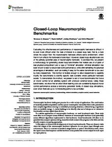
model was laminar by selecting viscous heating. The heat input in evaporation section depended on the power input. According to the general temperature requirement of electronic cooling and the experimental results by Lin et al. [16], the heating power used in simulations was not over 90 W. The volume fraction (amount of liquid and vapor) at regular time (10-60s) intervals for the pure water PHP is represented in Fig. 9. The adiabatic section was set as insulation boundary condition. The vapor generation starts at boiling temperature of working fluid, and filling ratio w as 50%. On the scale chart, blue color represents pure water and red color for pure vapor, and in between a combination of liquid and vapor. Initially, the volume fraction is orderly as velocity of flow is less, and thereafter increases. The amount of liquid decreases simultaneously as vapor increases with the run time. The simulation follows the evolution of the temperature for 60s duration, to reach a stable operation. From the counter observation of volume fraction, it is clear that the working fluid is circulated: alternating vapor and liquid phase appeared in the adjacent channels, after it reached stable oscillation. Simulation result also proved that the heat transfer process of CLPHP depends upon the fluid oscillation, which agrees with the flow visualization. The experimental and CFD simulation results for water CLPHP are presented in Fig. 10. The results show close agreement, i.e., the trends of experimental and simulation results are the same, having small error (about 5 %-10%). In both cases, initially the thermal resistance drastically decreases up to 40W heat input, and thereafter steadily decreases. The reasons for the variation in simulation and experimental results are the heat loss to the condenser tank and evaporator tank, the convection heat loss taking place at condenser and evaporator sections; also some errors are present in CFD simulation like discretization error.
4. Summary and conclusions Based on the experimental study the conclusions are summarized as follows: Thermal performance is quantitatively contributing on boiling point and latent heat of vaporization of working fluid. In addition, dynamic viscosity and surface tension also play an important role to drive liquid slug against gravity in vertical position for circulation.
P. R. Pachghare and A. M. Mahalle / Journal of Mechanical Science and Technology 28 (8) (2014) 3387~3394
3393
Acknowledgment This work was supported by Government College of Engineering, Amravati, (M.S.) India under TEQIP. The authors express their sincere appreciation for all of the support provided.
Nomenclature------------------------------------------------------------------------
(a)
(b)
(c)
D Eö g P Q R T U
: Tube diameter : Eötvös number : Gravitational acceleration : Electrical input power : Heat input : Resistance : Temperature : Uncertainty
Greek symbols
s ρ
: Surface tension (N/m) : Density (kg/m3)
Subscripts (d)
(e)
(f)
Fig. 9. Volume fraction at (a) 10 Sec.; (b) 20 Sec.; (c) 30 Sec.; (d) 40 Sec.; (e) 50 Sec.; (f) 60 Sec. time interval in CLPHP.
a c cri e liq th vap
: Adiabatic section : Condenser section : Critical : Evaporator section : Liquid : Thermal : Vapor
Abbreviations BHM : Bottom heat mode PHP : Pulsating heat pipe CLPHP : Closed loop pulsating heat pipe
References
Fig. 10. Thermal resistance for water PHP.
Thermal performance of binary fluids is better than pure working fluids of its constituents. Initially, the performance decreases sharply, thereafter behaves steadily for longer time. Flow patterns are changing from bubbly to slug and wispyannular to annular. Up to 40 W heat input, in the upward flow, bubbly and slug flow patterns are observed, due to against gravity. Whereas in downward flow, semi annular and annular flows are observed. For high heat input, gravity effect is negligible. Star CCM+ provided the simulation result in good agreement with experimental results, by considering the unsteady, surface tension and volume of fluid model.
[1] H. Akachi, Structure of a heat pipe, U. S. Patent 4921041 (1990). [2] M. Shafii, A. Faghri and Z. Yuwen, Thermal modeling of unlooped and looped pulsating heat pipes, ASME Journal of Heat Transfer, 123 (2001) 1159-1172. [3] M. Shafii, A. Faghri and Z. Yuwen, Analysis of heat transfer in unlooped and looped pulsating heat pipes. International Journal of Numerical Methods Heat Fluid Flow, 12 (5) (2002) 585-609. [4] B. Tong, T. Wong and K. Ooi, Closed loop pulsating heat pipe, Applied Thermal Engineering, 21 (18) (2001) 18451862. [5] S. Khandekar, N. Dollinger and M. Groll, Understanding operational regimes of closed loop pulsating heat pipes: An experimental study, Applied Thermal Engineering, 23 (2003) 707-719. [6] S. Khandekar, P. Charoensawan, M. Groll and P. Terdtoon,
3394
P. R. Pachghare and A. M. Mahalle / Journal of Mechanical Science and Technology 28 (8) (2014) 3387~3394
Closed loop pulsating heat pipes part B: visualization and semi-empirical modeling, Applied Thermal Engineering, 23 (16) (2003) 2021-2033. [7] S. Khandekar and M. Groll, An insight into thermohydrodynamic coupling in closed loop pulsating heat pipes, Int. J. Thermal Science, 43 (1) (2004) 13-20. [8] M. Mameli, S. Khandekar and M. Marengo, An exploratory study of a pulsating heat pipe operated with a two component fluid mixture, Proc. of ISHMT-ASME Heat and Mass Transfer Conference (2011). [9] P. Pachghare and M. Mahalle, Effect of pure and binary fluids on closed loop pulsating heat pipe thermal performance, International Journal of Procidia Engineering, Elsevier Publications, 51 (2013) 624 -629. [10] P. Pachghare and A. Mahalle, Thermal performance of closed loop pulsating heat pipe using pure and binary working fluid, Frontiers in Heat Pipes, 3 (2012) 033002. [11] S. Nagvase and P. Pachghare, Experimental and CFD analysis of closed loop pulsating heat pipe with DI-water, International Journal of IEEE, (10) (2013)185-190. [12] H. Akachi, F. Polášek and P. Štulc, Pulsating heat pipes. Proc. of the 5th Int. Heat Pipe Symposium (1996) 208-217. [13] S. J. Kline and F. A. McClintock, Describing Uncertainties
in Single-Sample Experiments, Mechanical Engineering, 75 (1) (1953) 3-8. [14] V. P. Carey, Liquid-vapor phase-change phenomena, Taylor and Francis Publishing Company, New York, USA (2007) 399-434. [15] A. Faghri, Heat pipe science and technology, Taylor and Francis, New York, USA (1995) 803-855. [16] Z. Lin, S. Wang, R. Shirakashi and L. Zhang, Simulation of a miniature oscillating heat pipe in bottom heating mode using CFD with unsteady modeling, International Journal of Heat and Mass Transfer, 57 (2013) 642-656.
Pramod R. Pachghare received his Master’s degree in Thermal Power Engineering from Amravati University. He is an assistant professor of Mechanical Engineering at Government College of Engineering, Amravati, Maharashtra State, India. His research area is characteristic investigation of closed loop pulsating heat pipes. He received his master’s degree in Thermal Power Engineering from Amravati University.