less of an issue; 3) dealing with partial pixels within the PSF is less of an issue; 4) saturation due to A/D ..... tions), program star, 2nd program star (or 3rd comparison star), 2nd comparison ...... nights are shown in Figure 5, where the right ascension and declination scans in each case have been ..... use a 0.005-mage.
https://ntrs.nasa.gov/search.jsp?R=20010050209 2018-07-03T19:00:23+00:00Z
NASA/CP-2000-209614
Third William Ames
Workshop J. Borucki
Research
Moffett
Moffett
Center
Field,
Lawrence Ames
on Photometry
California
94035
E. Lasher
Research
Center
Field,
California
National Aeronautics
94035
and
Space Administration Ames Moffett
Research Field,
December
Center California
2000
94035-1000
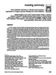
Acknowledgments The Third Workshop on Photometry was held at the SETI Institute in Palo Alto, California on September 24 and 25, ! 998. The workshop emphasizes equipment and software capable of routinely obtaining high precision when monitoring thousands of stars. The papers by Dunham, Borucki, Brown, Everett et al., and Henry discuss the instrumentation and software currently in use. Tests to identify the causes of photometric errors are described by Deeg and Doyle, Howell & Everett, Koch et al., Lockwood, and Mena-Werth.
Proceedings
of a workshop
held at the SETI Institute September
Available NASA Center for AeroSpace 7121 Standard Drive Hanover. MD 21076-1320 (301) 621-0390
Information
in Palo Alto, California
24 - 25, 1998
from: National
Technical
Information
Service
5285 Port Royal Road Springfield, VA 22161 (703) 487-4650
Introduction
The papers Alto,
California,
contained
The discoveries al. (1997),
herein
on September
were
of extrasolar
and others
have
presented
24 and 25,
planets
stimulated
at the workshop
by Wolszczan
a widespread
effort
their occurrence and characteristics. Doppler velocity with masses similar to that of Jupiter. Approximately orbital
periods
of a few days to a week
Doppler velocity measurements determined. Theoretical models astronomical
unit (AU)
held
at the SETI
Institute
in Palo
1998. (1994),
Mayor
to obtain
a body
techniques ten percent
are expected
to show
and Queloz
(1995),
of data sufficient
Butler
et
to understand
have found dozens ofextrasolar planets of the stars that show planets with
transits.
With
the mass
obtained
from
and the size from transit photometry, the densities of the planets can be of the structure of"hot Jupiters" (i.e., those planets within a tenth of an
of the parent
star) indicate
that these
planets
should
be substantially
larger
in size
and lower in density than Jupiter. Thus the combination of transit and Doppler velocity measurements provide a critical test of the theories of planetary structure. Furthermore, because photometry can be done with small-aperture should
also
several
thousand
telescopes
reduce
rather
than
requiring
the cost of discovering
To successfully
discover
stars, make
the use of much
extrasolar
extrasolar
planets
observations
larger
telescopes,
transit
investigators
must
photometry
planets. by the transit
with an hour-to-hour
method, precision
of two to three
monitor
parts
per
thousand, and observe the stars nearly continuously for several weeks. The required level of precision is difficult to attain on a routine basis, and the need to observe many thousands of stars suggests the use of small
telescopes
software Dunham,
with large
fields
of view
(FOVs).
Hence
the workshop
emphasized
equipment
and
capable of routinely obtaining high precision when monitoring thousands of stars. The papers Borucki, Brown, Everett et al., and Henry discuss the instrumentation and software currently
use. Tests to identify the causes Everett, Koch et al., Lockwood, Both photometers
of photometric errors and Mena-Werth.
based
on charged
coupled
are described
devices
by Deeg
(CCDs)
and Doyle,
Howell
and photomultiplier
tube
by in
&
detectors
(PMTs) are being used. The PMT detectors have been in use for many years; they show excellent precision when measuring night-to-night and year-to-year precision. However, even when skilled
relative
observers (Lockwood) or robotic systems (Henry) are employed, PMT systems can monitor less than stars each night because of the need to move from star to star. Hence these systems are most
100
advantageously employed to examine stars that have already been identified by the Doppler velocity technique as having planets. CCD detectors and wide FOV lenses allow many thousands of targets to be monitored systems discover
simultaneously, based on PMTs. planets.
but are just Wide
beginning
FOV systems
to provide
are best suited
the precision to searching
obtained a large
by the well-established area of the sky to
References Butler, R. P.; Marcy, LI15. Mayor,
G. W.; Williams,
M. and Queloz.
Wolszczan,
A.: Science
D.:
Nature,
vol. 264,
E.; Hauser, vol. 378,
1994,
H. and Shirts.
P.: Astrophys.
J. vol. 474,
1997,
p.
1995, p. 355.
p. 538.
iii
iv
Table
of Contents
Ultra-High Precision CCD Photometry. Steve B. Howell and Mark E. Everett ...................................................................................................
1
A Case Study Illustrating the Practical Limitations of Precision Photoelectric Photometry. G. W. Lockwood ...................................................................................................................................
9
Techniques for Automated Single-Star Photometry. Gregory W. Henry ...............................................................................................................................
25
Semiautomated Precise Photometry. E. W. Dunham ......................................................................................................................................
47
A Performance Comparison for Two Versions of the Vulcan Photometer. W.J. Borucki, D. A. Caldwell, J. M. Jenkins, D. G. Koch, and R. L. Showen ..................................
63
The Effects of Focus Settings on S/N and FWHM for Stars in a Crowded Field. Jose Mena-Werth .................................................................................................................................
71
A Testbed Search System for Extra-Solar Planet Transits at the University of Wyoming. Mark E. Everett, Steve B. Howell, and Derrick Ousley .....................................................................
79
VAPHOT - A Package for Precision Differential Aperture Photometry. Hans J. Deeg and Lawrence R. Doyle .................................................................................................
85
An Astronomical Test of CCD Photometric Precision. David G. Koch, Edward W. Dunham, William J. Borucki, and Jon M. Jenkins ...............................
95
vi
Ultra-High
Precision
Steve
B. Howell
CCD and Mark
Photometry E. Everett
Department of Physics and Astronomy Universi O, of Wyoming Laramie,
Wyoming
82071
Abstract Many
applications
in modem
coupled device (CCD) photometry. regime of usage for CCD detectors unconsidered. were unknown
ratio (S/N)
with undersampling
issues, intra-pixel likely to be error performed
astrophysics
require
ultra-high-precision
charged
of precision ( 0.002 Ns_,.s
type
photometry
mag)
lacks For Henry
et
of 3% to 4% or greater)
as a function No. variable (%)
B8-B9
2
0.0
0.0-0.1
A0-A3
8
37.5
0.1-0.2
A4--A7
8
25.0
0.2-0.3 0.3-0.4
A8-A9 F0-F3
16 57
62.5 29.8
0.4-0.5 0.5-0.6
F4-F7 F8--G0
151 132
8.6 18.9
0.6-0.7
G1-G6
87
33.3
0.7-0.8 0.8-0.9
G7-G9 K0-K1
29 32
24.1 31.2
0.9-1.0
K2-K3
47
34.0
37 27
35.1 40.7
K4 K5
both groups
to be variable. Stars bluer than results are useful for locating
-0.1-0.0
1.0-1.1 1.1-1.2
38
short
stars. types
stars are low-amplitude variables. stars, most of which were variable,
al., (1999) found that only a few percent of the variables (those were identified as such in the HIPPARCOS CA TALOGUE.
- V color
stars in B - V later than 0.5 (F8
stars or the G and K giant
exhibit frequent variability. All stars redder than B - V = 1.4 were found B - V = 0.3 are also quite likely to be variable. Although the HIPPARCOS candidate
as
is still unknown
1.2-1.3 1.3-1.4
K7 K7-M0
18 11
66.7 54.6
1.4-1.8
M0-M8
16
100.0
orB
- V
Theseresultsseemto range
F4-F7.
choice
However,
is not so clear.
when Since
indicate
long-term
0.0001-0.0002 mag with the APTs, observed to vary significantly from long-term
variability
((Ylong
0.0005
>
long-term
long-term
stability
(year-to-year)
stars should
is also required
variability
mag)
derived
from
be chosen
to 0.001 mag the percentage
the 0.75-m
from the spectral
in the comparison
can be measured
many stars that are constant year to year. Table 5 shows
0.80-m APT results are not included term variability. In the range F4-F7, have detectable
that the best comparison
excellent
stars,
to a precision
from night to night are still of stars with measurable
comparison
and program
stars.
because it has not been operating long enough to characterize where less than 10% of stars are short-term variables, nearly
variability.
A better
place
to find
long-term
the
of
stability
is in the range
The long60%
F0-F3;
even better odds occur at A8-A9. However, the chance for short-term variability in these ranges increases from less than 10% at F4-F7 to over 60% at A8-A9. The mid-F stars presumably have sufficient
convection
long-term pulsating
brightness changes. The late-A 8 Scuti and 7 Doradus variables.
zones
in which
location in the HR diagram term stability.
where
magnetic
dynamos
still operate
and early-F stars The disappointing
stars are likely
and drive
lack the magnetic and frustrating
to be found
small,
but significant,
dynamo, but many are result: there seems to be no
with the desired
level
of short-
and long-
Since many of the program stars on the 0.75- and 0.80-m APTs are solar-age and older, with very luminosity changes from year to year, the highest possible stability is needed in the comparison
small
stars to resolve unambiguously the variability in the program stars. proven variable, they are replaced with new ones. The replacements among
the late-A
and early-F
spectral
types,
will turn out to be new short-term variables, replaced. Alternatively, if new comparisons before
it becomes Table
obvious
5. Percentage
that they
Main
short-term
A8-F3
stability
is so important.
stars
have a very good
(Olong > 0.0005
sequence
spectral
Nst_rs
type
mag)
0.0 12.5
0.3-0.4 0.4-0.5
F0-F3 F4-F7
30 76
36.7 57.9
0.5-0.6
F8-G0
61
59.0
0.6-0.7 0.7-0.8
G1-G6 G7-G9
38 14
65.8 57.1
0.8-0.9
K0-KI
21
81.0
0.9-1.0 1.0-1.1
K2-K3 K4
17 9
70.6 33.3
9 2
66.7 100.0
K5 K7
appear
variability.
to be constant
many pass
of exhibiting ofB
- V
(%) 4 8
variability
chance
are
No. variable
A4-A7 A8-A9
if they lack the short-term
Although and quickly years might
as a function
0.1-0.2 0.2-0.3
1.1-1.2 1.2-1.3
stability
The
of stars with long term variability
(mag)
amplitude,
long-term
these can be identified in a single season are chosen from the F4-F7 stars, several
are variable.
B - V range
long-term
because
Consequently, as comparison stars are now chosen primarily from
In fact, even most from
of those
with observable
low-
year to year.
39
Observations
of Sun-Like
Stars
The approximately 150 sun-like stars being monitored by the 0.75- and 0.80-m APTs are plotted in figure 10, which shows their distribution in the logR'nK (age) versus B - V(mass) plane. Open circles are from the 0.75-m APT; filled circles are from the 0.80-m APT. The stars range in mass from about 1.3MG on the left to 0.7MQ on the right. They range in age from 100 Myr at the top to 10 Gyr at the bottom. The chromospheric emission ratios (IogR'HK) are computed from the Ca II H & K index as defined and determined by the Mount Wilson HK Project (Baliunas et al., 1998). For comparison, the sun is plotted as a circled point at a B - Vof0.642 and a IogR'HK of--4.901. Most of the 0.80-m APT stars were selected to be close to the sun in both mass and age. Therefore, this plot does not represent the natural distribution of nearby sun-like stars. b
-4.2
i
i
i
i
o
-4.4
0 % _' 0
0
% 0
o
o
0 0
-4.6
• o o
•° o oqL
o o
_
oo
o
•
.°Oo° o o
O
-5 -5.2
°e %o• o
°e_'_e o, •_ o ,
0.4
I
0.6
,
I
o _
0.8
I
1
,
I
1.2
i
1.4
B-V Figure 10. The distribution in logR'14x (age) and B- V (mass) of the 150 sun-like stars being monitored with the O.75-m (open circles) and 0.80-m (filled circles) APTs. The position of the sun is plotted for comparison. Short term photometric
variability
(t_sho,,t)in this sample of stars is shown in figure 11, where the
symbols are used in the previous figure. The standard deviations are derived from the differential magnitudes computed with respect to a constant comparison star in each case. In this figure, age increases from left to right from 100 Myr to 10 Gyr. As a lower main-sequence star ages, its rotation slows, its dynamo weakens, and its chromospheric emission ratio decreases. As seen in the figure, this is accompanied by a decrease in the amplitude of short-term photometric variability. Corresponding standard deviations (_sho,-t)decrease from nearly 0.03 mag to below - 0.0010 mag, which represents the limit of precision for a single observation. The standard deviations from the 0.80-m APT lie systematically somewhat below those from the 0.75-m APT because longer integration times were used with the two-channel photometer on the 0.80-m APT. The day-to-day photometric variability of the sun is represented by the two circled points, based on satellite radiometer measurements and corrected for the difference between total solar irradiance and the Strrmgren b and v band passes (Radick et al., 1998). The lower of the two represents the photometric variability of the quiet sun during sunspot minimum, while the upper symbol represents solar variability during sunspot maximum. It is clear that the APT observations will not, in general, resolve night-to-night variations in sun-like stars older than the sun.
40
0.030
'
_ ....
I ....
I
....
I ....
i
0.00
0.025 0.00:
0,020'
%
o
080
0.001
o
o
•_
o
o o %
•
,
o•
•a
® 0.000
....................... , _ ....
0.015
I ....
-4.80
"4 r_
I ....
I ....
-4.90
..4,85
I
-495
-5.00
O O
log R'ur
0.010 QO
0
gO
o
0.005
o
%0°
% oo
0.000
-4.2
-4.4
-4.6
-4.8 log
Figure APT
11. (open
Short
term variabili_
circles)
The photometric lower circled resolved.
and the 0.80-m variability
points
Figure There
12 shows
a young
F8 V star.
APT
(filled
an example
of 150 sun-like
circles)
of the sun during
in the inset panel.
are two program
39587),
(trshord in the sample
as a function
sunspot
maximum
Night-to-night
of long-term
(- 800 Myr) GO V star.
stars
of differential
lo uncertainties by the square the yearly
computed
comers.
differentials.
variation
and the (C-A)
in Z J Ori,
panel
shows
these
observations
the relative that
brightness long term
The
(D-A)
and (C-B) variation variations
Dotted
of the yearly means
from
stars A and B exhibit and (D-B) panels between
means the mean
good
panels
show
clearly
a similar
and
mag cannot
be
program-star
Error
from
plot the six
bars are the
its yearly
mean
lines mark
are given
in the lower-left
of the means show
stability
program
of
comer
(_to,g) are given
of
in
0.005-mag
in 111 Tau.
mag can be followed
divided
the mean
with OJo,,g = 0.00022
a long-term
variation
groups.
(- 300 Myr)
The six panels
horizontal
long-term
the two variable
of 0.003-0.005
a young
observation
(age).
by the upper
Star D is Z J Ori (HD
over five years.
for the year.
of the yearly
Comparison
group.
respectively.
of a single
emission
0.0010
for one of the 0.75-m
stars,
with the O. 75-m
is shown
less than about
magnitudes
in magnitudes
deviations
mag for the (B-A)
mean deviation
of observations
The total ranges
the standard
the lower-right
yearly
observed
of chromospheric
Star C is 111 Tau (HD 35296),
as the standard
root of the number
means.
each panel;
(b + y)/2
stars
in this particular
Stars A and B are F0 III and F0 V comparison
combinations
-5.2
and minimum
variabili_,
variability
stars and two comparison
-5.0
R'_
stars. easily
The (D-C)
It is clear
from
with the APTs.
41
-o.gg
(b÷7)/2
-0.985.... 1........... i
-0.08
"
,
_
d-_ l
_ ........................
....
i
....
_
i ............
....
i
i .....
....
I
O.O05g •
1
....
I
....
I
-1.015
....
I
.
.
.
i
J
f
-_.o_ .... _;........... I
_,._
'
I
'
"1
0.00_02
_
....
T
_ ...........
....
I
....
o.o_9 ............ I
._ i1
d-b
_.........................
....
,
_ ..... I
•
•
0;00!91, I
I
I
I
-0.595
d-c
-o..
.... _............
_.........................
_ .................
-0.585 -0.58
0.00255
0.0066
C--8.
-0.39_
-0.425
0.024
b'--
o.
............ oo, I
.....
1994
Figure 12. Long-term
variability
1095
,
,
i
1995 Year
,
.
I
"
............ ..... o;ooo l ,
1997
....
1998
in the young GO V star _ Ori (star D) and the young F8 V star 111 Tau
(star C) as observed relative to two constant comparison stars (A and B) with the O.75-m APT. Longterm variations of O.003-0.005 mag can be followed easily with the APTs.
Figure 13 shows the long-term photometric behavior of the older (- 4 Gyr) GO V star HD 176051 (star D) relative to three comparison stars HD 173417 (F1 III-IV, star A), HD 178538 (F0, star B), and HD 172742 (F5, star C). Stars A and B show good long-term stability with Ojo,g = 0.00021 mag for the (B-A) differential magnitudes. HD 176051 shows clear long-term variability of about 0.0015 mag in panels (D-A)and (D-B). Comparison star C also shows obvious long-term variability of about 0.002 mag over six years in panels (C-A) and (C-B). Thus, with suitably constant comparison stars, the APTs are also capable of resolving small luminosity changes in the solar-age program stars.
42
-0.399
(b+y)/2
d-a
-0.398
-0.367
....
1...................
_...................
_.............
-0,090 0.0015 -0.395
0.00055
....
' '
-1.865
'
'
'
I
"
'
'
•
'
J
'
,
'
"
"
'
'
....
,
'
....
,
•
' •
•
"
I
"
'
'
•
'
'
d-b -1.864
-1._3 .... _......... -1.562
:
0.0014
•
•
!
_ ..........
_.................................. 0.00052
,
,
,
|
,
,
,
,
I
,
•
•
.
t
....
I
....
a
.
.
-;_.032
,
,
d-¢
-2.03
1 ............................
...i
t i .....................
_ .....
-2.O28
t 0.0025 ....
-2.026
,
....
,
....
'
....
'
....
,
,
0.00003 , , ,
1,63
c
1.632] ...|
..................................................
t
o.oo24 , , ..................... ....
i
....
I
a
"
o,.,(x_, ....
,
....
1
....
i
"
•
0.164
"
c-b
o.166" "I 0,160
_
_
_"
0,0020 ,
,
0,00083 .
.
....
l
....
I
i •
'
"
.
.
.
i
i
....
l
,
....
I
i '
•
"
,
,
|
,
1
1.465
b-a
"" .......................i................... ....... ..... 1.467
0.0006 .
,
0,00021 ,
,
I
....
|gR4
I
....
1995
I
,
,
,
|gQ6
,
I
,
,
,
191;FF
•
l
....
1698
|690
Year
Figure
13.
Long-term
variabili
O, of only
0.001
mag
over several
176051 (star D) is clearly resolved relative to comparison Comparison star C is also a long-term variable.
Search
for Extrasolar Recently,
discovered
several
years
in the solar-aged
stars A and B with
GO V star HD
the O. 75om APT.
Planets of the sun-like
to have planetary-mass
stars being
companions
monitored
by the 0.75-
with surprisingly
short
and 0.80-m
periods
(e.g.,
APTs
Marcy
have been
and Butler,
1998, and references within). Since all the new extrasolar planets have been detected indirectly via radial-velocity techniques, independent observations are needed to confirm that the observed radialvelocity variations are not due to star-spot and pulsations should both be accompanied, confirmation reported
of extrasolar
planetary-orbital
planetary periods
effects or pulsations in the stars themselves. Since star spots at some level, by light variations, the APTs can assist in the
candidates (Henry
by searching
et al., 1997; Baliunas
for brightness et al.,
variations
in the stars
on the
1997).
43
Figure 14 shows six seasons of nightly Strrmgren (b + y)/2 differential magnitudes of the F7 V star x Boo from the 0.75-m APT. The observations are plotted modulo the 3.31275-day orbital period of the > 3.39Mjup planetary companion, reported by Butler et al. (1997). Phase 0.0 corresponds to the time of conjunction when the companion would transit the star for suitable orbital inclinations. A least-squares sine fit at the orbital period yields a semi-amplitude of0.00011 + 0.00009 mag, indicating no light variability on the planetary period to one part in 10 4 . This supports the hypothesis that the observed radial-velocity variations in T Boo are, indeed, due to a planetary companion. The APT photometry also supports similar conclusions for other sun-like stars with reported planetary companions (Henry et al., 1997; Baliunas et al., 1997; Henry et al., 1999).
-1.7 +'_-
1.605
-I.BO -1.685 0.8
0.0
0.2 Plemetary
0.4 Orbited
0.6
0.8
Phue
Figure 14. Six seasons of nightly Str6mgren (b + y)/2 differential magnitudes of the F7 V star _:Boo from the O.75-m APTplotted modulo the 3.31275-day orbital period of the purported > 3.39MJup planeta_ companion. No light variability is observed to one part in 104, supporting the existence of the planeta_ companion as the cause of the observed radial-veloci_ variations in this star.
Figure 15 shows the observations ofx Boo from figure 14 near the time of conjunction replotted with an expanded scale on the abscissa. An additional night of monitoring observations with the 0.80-m APT has been added. The solid line shows the predicted depth (0.008 mag) and duration (3.6 hr) of the transit for a 1.2Rj_p planet across the 1.4R@ star. The detection of such a transit would resolve the inclination-angle ambiguity and allow the actual, as opposed to the minimum, mass of the planet to be computed from the radial-velocity observations. The observed depth of the transit would provide a measure of the size of the planet and, thus, its density. These parameters are important for improving theoretical models of the compositions and origins of these strange, new planets. Figure 15 shows conclusively that transits do not occur in "cBoo. Similar APT observations of six additional sun-like stars with Jupiter-mass planets in short-period orbits also reveal no transits, in spite of an overall 50% probability of finding at least one transit in the sample. With the discovery of a few additional shortperiod planets, the probability for the detection of a transit will increase to about 70%. The successful observation of a transit would represent the first direct detection of an extrasolar planet.
44
!
!
'
i
!
-1.7
'" ." o. ooo A
:"
- 1.695 ,0
.°
".
:-
%
_ . ._o
_o_,
o
o
-1.69 oo
- 1.e85
i
i
0.94
,
I
0.96
_
0.98
expanded
15.
Photometeric scale
observations
on the abscissa.
I
night
I
,
0.02
Orbital
of r Boofromfigure
An additional
,
0.00
Planetary
Figure
ol
i
0.98
circles)
replotted
Phaee
14 (closed
of monitoring
I
0.04
observations
been added (open circles). The solid line shows the predicted depth and duration planeta O, companion. Although the probabilio, of transits is 14% in this system, show that they do not occur.
with an
with the 0.80-m
APT has
for the transits the observations
of the clearh,
Acknowledgements Many thanks to Lou Boyd and Don Epand for their efforts at Fairborn Observatory. Astronomy with automated telescopes at Tennessee State University has been supported by the National Aeronautics and Space Administration, most recently though NASA grants NAG8-1014, NCC2-997, and NCC5-228 (which
funds
TSU's
Center
for Automated
Space
Science),
and the National
Science
Foundation,
most
recently through NSF grants HRD-9550561 and HRD-9706268 (which funds TSU's Center for Systems Science Research). The planetary search program is also partially supported by the Richard Lounsbery Foundation. My thanks also go to Stephen Henry for preparing figure 9 and tables 4 and 5 from the APT data bases.
45
References Aerts, C.; Eyer, L.; and Kestens, E.: Astronaut & Aeronaut., vol. 337, 1998, p. 790. Baliunas, S. L.; Donahue, R. A.; Soon, W.; and Henry, G. W.: In The 10th Cambridge
Workshop
on Cool
Stars, Stellar Systems, and the Sun, ASP Conf. Ser. 154, R.A. Donahue and J. A. Bookbinder eds., San Francisco: ASP, 1998, p. 153. Baliunas, S. L.; Henry, G. W.; Donahue, R. A.; Fekel, F.C.; and Soon, W. H.: Astrophys. J., vol. 474, no. L119, 1997. Boyd, L. J., et al.: International Amateur-Professional Photoelectric Photometry Communication No. 52, 1993, p. 23. Butler, R. P.; Marcy, G. W.; Williams, E.; Hauser, H.; and Shirts, P.: Astrophys. J., vol. 474, no. L115, 1997. Crawford, D. L.; and Barnes, J. V.: Astrophys. J., vol. 75, 1970, p. 978. Eaton, J. A.: In Robotic Telescopes: Current Capabilities, Present Developments, and Future Prospects for Automated Astronomy, ASP Conf. Ser. 79, G. W. Henry and J. A. Eaton, eds., San Francisco: ASP, 1995, p.226. Edgington, W.; Drummond, M.; Bresina, J.; Henry, G. W.; and Drascher, E.: In New Observing Modes for the Next Century, ASP Conf. Ser. 87, T. Boroson, J. Davies, and I. Robson, eds., San Francisco, ASP, 1996, p. 151. Hardie, R. H.: In Astronomical Techniques, W. A. Hiltner, ed., Chicago: University of Chicago Press, 1962, p. 178. Hatzes, A. P.; and Cochran, W. D.: in The 10th Cambridge Workshop on Cool Stars, Stellar Systems, and the Sun, ASP Conf. Ser. 154, R. A. Donahue and J. A. Bookbinder, eds., San Francisco: ASP, 1998, p. 311. Henry, G. W.: In New Observing Modes for the Next Century, ASP Conf. Ser. 87, T. Boroson, J. Davies, and I. Robson, eds., San Francisco, ASP, 1996, p. 145. Henry, G. W.; Baliunas, S. L.; and Donahue, R. A.: Astrophys. J., 1999, in preparation. Henry, G. W.; Baliunas, S. L.; and Donahue, R. A.; Soon, W. H.; and Saar, S. H.: Astrophys. J., vol. 474, 1997, p. 503. Henry, G. W.; Fekel, F. C.; Henry, S. M.; and Hall, D. S.: Astrophys J., 1999, in preparation. Lockwood, G. W.; Skiff, B. A.; and Radick, R. R.: Astrophys, J., vol. 485, 1997, p. 789. Marcy, G. W.; and Butler, P. B.: In The 10th Cambridge Workshop on Cool Stars, Stellar Systems, and the Sun, ASP Conf. Ser. 154, R. A. Donahue and J. A. Bookbinder, eds., San Francisco: ASP, 1998, p.9. Perryman, M. A. C., et al.: The Hipparcos and Tycho Catalogues (ESA: The Netherlands), 1997. Radick, R. R.; Lockwood, G. W.; Skiff, B. A.; and Baliunas, S. L.: Astrophys. J., vol. 118, 1998, p. 239. Soon, W. H.; Posmentier, E. S.; and Baliunas, S. L.: Astrophys. J., vol. 472, 1996, p. 891.
46
Semiautomated
Precise
Edward Lowell
Photometry
W. Dunham
Observatoo,,
1400 Mars
Flagstaff
AZ
Hill Road,
86001
Abstract
requires
Application
of the transit
acquisition
of a large
photometry
amount
period of many weeks. The observational so we have made a semiautomated system location. This is a compromise complexity of a robotic system. The equipment mounted
at the focal
between
currently plane
method
for detecting
of photometric
extrasolar
giant
data on each of several
inner
thousand
planets
stars
over a
workload is very high if these data are obtained manually, to carry out the observations at Lowell's Mars Hill the observational
in use consists
effort
of a Loral
of an Aero-Ektarfl2.5
aerial
of a manual
2Kx2K
camera
charged
system
and the
coupled
device
lens with 30.5-centimeter
(CCD) (cm)
focal
length. The CCD camera system is the modified SNAPSHOT camera system (Dunham, et al., 1985; Dunham, 1995). It is set up to take a large number of exposures unattended during the night. The camera and dewar are mounted on a Celestron Computstar an SBIG ST4 autoguider attached to a Celestron C90 guide The current
system
addition, if the weather protection. A proposed
needs
to be set up manually
14 telescope telescope.
each night
deteriorates during the night, the equipment upgrade to the current hardware will allow
remotely. This in turn will allow remote Anderson Mesa site.
the system
to operate
efficiently
mount
and stowed
and autoguided
with
each morning.
In
must be manually stowed for these functions to be handled at Lowell's
darker
but more
Introduction
The recent
discovery
of giant
axes has dramatically increased This development has prompted and the NASA
Ames
Research
planets
orbiting
other
stars in orbits
with very
Center
to begin
work
on photometric
searches
extrasolar giant inner planets. This paper describes the instrumentation used in the search that is beginning at Lowell Observatory.
Within the 120-star sample inner planets (Butler, et al., 1997). For the giant
inner
semimajor
planets. Observatory,
for transits
and observational
The photometric problem is defined by two main factors: 1) the probability field star possesses a giant inner planet with suitable orbital inclination and period; photometric signature of the transit by the planet.
is R*/Rorbit.
small
the a priori probability of detecting transits by extrasolar investigators at Lowell Observatory, the High Altitude
by processes
that a given and 2) the
searched by Butler and Marcy, approximately 3% have giant The probability that an extrasolar planet will transit its parent
planets
already
known,
this is approximately
10%.
Thus
star
the odds
that a star in the Butler and Marcy sample will show transits is -1:300. The overall probability that a field star will show transits is not as clearly defined because of the selection criteria that were applied in deriving the Butler and Marcy sample. They included stars with surface temperatures similar to the sun's and low rotational that close
binaries
account
velocities,
and excluded
for half of all stars (Allen,
known 1976),
spectroscopic
binaries.
and that half of the stars
If we assume in a given
field
47
at 10th-12th magnitude are stars
in a given Figure
field
F-K main sequence
that are F-K dwarfs
1, provided
by T. Brown,
stars (Allen,
showing
transits
shows
the fraction
1976),
by giant
we conclude inner
of transits
planets detected
that the fraction
of
will be -1:1200. as a function
of
orbital period for a six-week observing run. It shows the case for both a single site and a network of three sites all located in the western U.S. The weather is assumed to be good enough for differential photometry Observations detection transits. site.
35% of the time at each site, and is further assumed are assumed to be taken for seven hours per night.
to be uncorrelated among sites. The top pair of curves is for
of two transits, the middle pair for three transits, and the bottom one for four detected The solid curves are the detection rates for three sites and the dashed curves are for a single
With
three
sites,
or 40% respectively, field stars will show for every sites.
the fraction
of stars with two or three
detected
transits
is approximately
depending on the distribution of sites. This figure, together transits, indicates that we will need to observe approximately
star showing
two or three
detected
1.0
transits
.........
in a six-week
, .........
coordinated
75%
with the odds that 1600 or 3000 stars observing
run at three
, .... n=2,34""-'-'-,-""
0.6
0.0
_...2_ 3
4
5
Orbit Period
Figurr ! obser_'ing
Thr l,redicted run at _'ither
fi'action of stars one (dashed line)
6
7
(Days)
exhibiting transits that are actually detected in a six-week or three (solid line) sites located in the western U.S.,
accotmtmg tor _v_'ather and the diurnal cycle. The top pair of curves svstem_ tor _ hlrh two transits are detected. The middle pair reflects transits,
and
thr t_ttom
The giant depend
only weakly
inner
pair
planet
on their
shows
the fraction
models mass
with four
of Guillot,
in the range
detected
et al. (1996)
of 0.5-3
Jupiter
shows the fraction of transiting the fraction with three detected
transits.
indicate masses.
that the radii of these Radii
range
objects
from
approximately 0.5 Jupiter radii to about 1.2 Jupiter radii, depending on composition. Thus we expect a transit depth on the order of 1/4% to 1.4% depending on planetary composition and stellar size. The duration of a transit is approximately 2.5-3 hours for objects with periods of--4 days and orbital
48
radiiof-0.05 astronomical unit(AU). differential
signal/noise In summary,
photometry
(S/N)
ratio
the photometric
of several
thousand
Therefore,
of 0.1%
to detect
to 0.5%
problem
to be solved
stars in a crowded
a transit
reliably,
in an integration
field.
requires It turns
we need
time of-30
to achieve
a
minutes.
millimagnitude
differemial
out that star densities
are such that
the aperture of the telescope used for the photometric search is not very important, but the focal ratio is very important. For a givenflratio and detector, a larger telescope can achieve a good S/N ratio on fainter
stars,
but the field area is smaller,
so the number
of target
stars remains
approximately
the
same. We have elected to pursue the small telescope, wide-field option because follow-up radial velocity observations will be more successful with brighter stars, and because the equipment is less expensive. Instrumentation The instrumentation
in current
borrowed because camera described
the project by Dunham
illuminated
2Kx2K
inch focal arcseconds mounted
Loral
use for the Lowell
extrasolar
is not funded. The detector system (1995) and Dunham, et al. (1985).
CCD.
The "telescope"
planet
search
project
is largely
is the modified SNAPSHOT CCD This system incorporates a front-
is an J72.5 Aero-Ektar
aerial
camera
lens with
12-
length that was in storage at Lowell. The complete system provides a plate scale of 10.0 (arcsec)/pixel and a field of view of 5.7 degrees. The camera lens and CCD dewar are on a Celestron
Compustar
14 telescope
mount.
A Celestron
C90 guide
telescope
is used
with an SBIG ST-4 CCD autoguider to provide guiding for the system. The entire assembly, shown in figure 2, is mounted in a small roll-off roof building at Lowell's Mars Hill site not far from the astrograph
used
Figure
The equipment
2.
by Clyde
Tombaugh
to discover
used for the Lowell
Pluto.
search
for extrasolar
giant
inner planets.
The Aero-
El'tar lens is in the gray cylindrical housing. The CCD dewar is normally mounted on the rectangular part of the lens housing, but is not mounted in this image. The filter wheel is located inside
the lens assembh,.
The built-in
shutter
in the lens is used as the system
shutter.
49
The filter used for observations
to date, which we call the VR filter, is essentially
a
combination of the V and R passbands (BesseU, 1976, and Bessell, 1990). It consists of 2 millimeters (mm) of Schott GG-495, normally used to provide the blue cutoff for a V filter, and 2 mm of Schott KG-3, normally used to provide the red cutoff for an R filter. This filter was selected in order to maximize the bandpass within the image quality constraints imposed by the chromatic aberration of the lens. The chromatic behavior of the lens was found by finding the focus blur as a function of wavelength. Image full width at half maximum (FWHM) values were found to be 7, 3.4, 2.5, and 9 pixels in the B, V, R, and I passbands, respectively. Neither a calculation nor an observational check has been carried out to see if the VR filter provides the best S/N ratio compared to, say, V or R. The flat-field
screen consists of an aluminum
illuminated by the twilight sky to minimize gradients suggestion of Chromey and Hasselbacher (1996).
plate painted flat white.
This plate is
over the wide field of the system, following
the
It was found during the first full-moon observing cycle that scattered moonlight from the lens was the major contributor to the sky brightness. As a result, a moon shade was made that did not vignette the field of view, but succeeded in keeping moonlight from falling directly on the lens. This shade reduced the sky background by about a factor of three. The SNAPSHOT control program is written in C language and runs under UNIX. It is command-line driven, with input coming from the standard input. As a result, it is trivial to run the program with its input redirected from a text file. A few modifications to the program were made to facilitate this mode of operation, and it can run unattended for an entire night under reasonably good weather conditions. The system is capable of operating in the presence of thin cirrus cloud cover, but cannot cope if the weather deteriorates substantially. Occasional crashes of the control software cause loss of data for the rest of the night because the system operates unattended after it is set up. Observing
Procedure
The activity for a typical observing night begins with acquisition of bias, dark, and flat-field frames. A SNAPSHOT control script was written to take dark and bias frames, and another script for flat-field frames was also written. In principle, these could have been combined, but manual intervention is currently needed to ensure that light leaks in the camera do not corrupt the dark frames. The fiat-field script was "tuned" so that good signal levels are obtained as twilight progresses. angle.
All that needs to be done is for the script to be started at a particular
When the calibrations are complete,
the telescope
solar depression
is pointed at the target field and the liquid
nitrogen dewar is filled to capacity. Then the field is acquired and the autoguider is "trained" and autoguiding begins. Finally, a test frame is taken to ensure that the system is operating correctly and the SNAPSHOT program is restarted using the night's observing script. The system is then left until the next morning. A microswitch tunas off the telescope drive when the hour angle reaches a predetermined value. In the morning, the telescope is stowed, the dewar is topped off, and a tape backup of the previous night's data is generated. The ST-4 autoguider has an annoying cutoff on the guide star brightness. If the brightness of the peak pixel of the guide star drops below half of the value it had when the ST-4 was set up, it will automatically stop trying to track. If it gives up tracking long enough for the guide star to leave its small field of view, it will fail to regain track and the remainder of the night's work will be lost. This problem
50
can occur if cirrus clouds pass through during an otherwise
good night.
Also, the C90 guide
telescope
focus
drifts
somewhat
as a function
of zenith
distance,
causing
the peak pixel
brightness
to
change.
setup
We circumvent loss of track in two ways. First, we cover half the aperture of the C90 during so that it is "fooled" into "thinking" that it is tracking on a fainter star. This works very. well;
evidently the ST-4 focus as a function
has no cutoffifthe guide of hour angle for a given
the focus
range.
variation
The amount of manual intervention instrumentation is located near the Lowell darker, more remote efficient operation.
site, additional
star becomes too bright! Second, we calibrated the C90 field and offset it so that the focus is set in the middle of
required is marginally acceptable because the offices on Mars Hill. If the equipment is moved
automation
and remote
operation
capability
provides
star images
to a
will be needed
for
Performance Image pixels
Quality.
or 25 arcsec
probably bandpass
The system
FWHM.
The image
chromatic in nature using photographic Tracking
as described profile
since these materials.
Performance.
lenses
has a sharp were
The autoguider
core with rather
designed
works
in the VR filter
quite
to be used
well,
extended
with 2.5 wings.
This
over a more
restricted
but the C90 guide
telescope
is
has
internal flexibility that causes tracking errors to occur, as well as the focus drift already mentioned. The tracking errors are mainly in the east-west, or column, direction, as seen in figure 3. No attempt was made
to correct
determine
how
for these
important
DuD" Cycle. frame in 94 seconds, 11 frames per hour.
drifts
the drifts
during
a night,
The SNAPSHOT
system
so the standard 240-sec The observing efficiency
Polar Alignment. toward the north celestial
and so far no analysis
are from a photometric
point
can read out and store
are available
an unbinned
(4-minute) exposures were was 72% for this exposure
A very effective method of polar pole and take a series of exposures
results
to
of view.
obtained time.
2Kx2K at a rate
CCD of nearly
alignment is to point the camera with the telescope tracking on.
system The star
positions move between exposures at a rate that is proportional to the time between exposures the angular offset of the telescope RA axis from the refracted pole. The position angle of the apparent refracted
building pointing
motion pole.
vector
is related
to the position
angle of the offset
This method was unfortunately not possible blocked access to the polar region. Instead, system.
We set on a star and updated
of the telescope
and
axis from the
to use for the Lowell system because the we used a scheme making use of the Compustar
the telescope
mount
coordinates.
The telescope
was
then swung through a few hours of RA to another star with nearly the same dec, and the difference in dec between the actual position of the star and the telescope dec readout was used to derive the offset of the telescope RA axis from the pole. After adjusting the telescope mount, the process was repeated, and iteration continued until the offset was about 3 arcminutes, which is about the limiting accuracy for the hardware used. This will result in field rotation on the order of+3 arcminutes over a night. The corresponding image motion of a star image is near the center of the CCD, should be about +1 pixel.
near the edge of the CCD,
if the guide
star
51
Autoguiding
I ----e--
Column
Position
830
I
'
Performance
---_
I I
I
'
'
I
'
'
f
'
E , , i
I
Row Position I
, , i
, i
994
828
993
x_ 826
33 0
=E "o
co
0
ffl o
_. 0
c
824
E
"g_. x
0
{/}
822
992
820
818
, i = , I , = i , , L , , i , , I 2:00:00 4:00:00 6:00:00 UT on
,
,
k
,
i
8:00:00
( , , i ,, 10:00:00
i
991
1997/12/27
Figure 3. The autoguider tracking performance. The column coordinate corresponds to right ascension (RA) and the row coordinate to declination (dec). The guide star, _ Aur, passed the meridian
at 7:06 universal
Theoretical have
not been
Photometric
analyzed
It is important transformation
(UT).
Performance.
yet, so photometric
to recognize to standard
Five sources target cirrus
time
The data from
performance
that the photometric photometric systems
of noise
are significant
for wide-field
30-minute
current period
are negligible (factoring
contributors. in the duty
cycle
scintillation of the target of the current
season
a theoretical
basis.
not requiring
photometry:
shot noise
on the
noise, differential extinction from thin stars across the CCD. CCD read noise
The contributions
magnitude for moonless conditions in figure 4. from data obtained in January 1998. Following
52
differential
observing
on only
problem is purely differential, or all-sky photometry.
stars, shot noise on the sky background, clouds, and noise introduced by motion
and dark
the 1997-1998
can be discussed
from the first three system)
are shown
noise
sources
as a function
in a
of stellar
The shot noise values are based on measured signals Young (1974; also Dravins, et al., 1998), we find
that the fractional
noise
due to scintillation
for our 12-centimeter
(cm) camera
aperture
is about
0.0007 in a 30-minute integration at two airmasses, accounting for our present duty cycle. Note the dominant noise source for most stars is shot noise on the 19.8-magnitude-per-square-arcsecond sky background
at Mars
Hill in the "VR"
We found during observations from thin cirrus clouds. With
suffered the field
occur.
comparison
This problem
stars
star.
to tens, but should substantially that would otherwise be lost. Potentially
filter.
in November a wide field
can be mitigated,
for a given
the most
1997 through January 1998 that many nights of view, noticeable transparency variations across
if not eliminated,
This will reduce decrease
serious
that
the number
the cirrus-induced
noise
source
by using
only nearby
of comparison
stars
noise,
is motion
allowing
operation
of the star images
stars as
from thousands
across
during
nights
the CCD.
We
have carried out laboratory tests at NASA Ames dealing with this issue (Robinson, et al., 1995, and Jenkins, et al., 1997). These tests indicated that if the star images are somewhat defocused, they are kept within
a pixel
is measured,
location,
fit, and subtracted
photometry in which
of the same
with commercial star images
and the apparent
from the raw brightness, CCDs
is better
than
are not kept in the same
10 "5.
place
brightness
change
the fractional Common
with position
stability
experience
is that precision
of differential with CCD
substantially
better
very difficult to achieve. The autoguider performance shown in figure 3 thus may Image motion due to differential refraction is less than a pixel above two airmasses earlier, well.
polar
Proposed
alignment
can be sufficiently
accurate
that field rotation
and focus
photometry than
0.50/o is
be troublesome. and, as noted
can be reduced
to this level as
Improvements
We have proposed to make many improvements to the system described here. the upgrades is to improve the data quality and reduce the manual intervention data. The major improvements include: •
Move the operation on the sky.
•
Reduce induced
•
Incorporate and improve
•
Modify manual
the telescope intervention.
•
Modify
the CCD
from Mars
the flexure in the guiding by image motion.
temperature
Hill to Lowell's
system
dark Anderson
so guiding
is good
Mesa
to about
The overall goal of required to obtain the
site to reduce
a pixel
to reduce
new CCD control hardware and software to improve the observational the ability of the system to work remotely and autonomously. control
dewar
operation
and autoguider
to use a cryocooler while
eliminating
systems
instead manual
to allow
of liquid
nitrogen
remote
nitrogen
the shot noise
operation
to maintain
the noise
duty cycle
with reduced
low-
fills.
53
0.1
"_ 0.01 Z
.....
Shot Noise on Star
....
_ Shi°ttillNtiite Nn ,SkeY
....
Total Noise
/
/
i--
.£ U-O.O01
....................
[/ 0.0001 9
10
11
12
13
14
15
"VR" Magnitude
Figure 4. The predicted differential S/N ratio for stars of various brightnesses. The contributors considered are shot noise on the star, shot noise on the s_, and scintillation noise. The solid line shows the Root Sum of Squares (RSS) total noise from these sources. See text for details and for discussion of additional noise sources.
An Optimized
Optical
System?
During the workshop we discussed the advantages of an optical system with an optimally blurred point-spread function (PSF) with minimal sharp edges or sharp features in it. I examined a folded field-flattened Schmidt design. The folding secondary mirror is nominally fiat, but if it is intentionally bent slightly, it introduces astigmatism. Although the resulting PSF is not optimal, it is far superior to the PSF of the Aero-Ektar lenses, and is worth consideration. The additional complication of an achromatic Schmidt provides better image quality, but may not be justified for this application. The basic optical system is a 10-inchfl.5 Schmidt, and is shown in figures 5a and 5b. Its corrector plate has a spherical curve, so reflections off the detector and back from the corrector plate are grossly out of focus by the time they reach the focal plane again. For manufacturing convenience, the radius of the convex spherical side is the same as the radius of the primary mirror. The primary mirror is anfl1.5 sphere, and the secondary is a stock flat mirror. A 4-mm-thick filter is the next optical element, followed by a two-element field flattener. The leading element is thick enough to serve as a dewar window. When used with a 2Kx2K CCD with 15 micron pixels, the image scale is 8.12 "/px and its square field of view is 4.6 degrees on a side. All transmissive optics can be optimized using either silica or BK7 with almost identical image quality.
54
The most likely mechanical configuration for this system would be to build the CCD camera into the primary mirror mount and attach the filter and shutter mechanism to the front of the
mount
CCD dewar. likely
The
secondary
be supported
from
mirror
a "tub"
could
attached
be supported
from the dewar
to the primary
mirror
as well,
but would
more
mount.
I _o L_YOUT l,_T tlm.L I_
atlll_
a_ml¢:H SlT_,_'IZOT
IJISt
LIB
I,_,,%_,_"'._.."?, I_
Figure section
allltl
II_
The optical enclosed additional meters
light curves astigmatism
corresponding
This amount
Figure
5b (right)
Detailed
optimization was done for a spectral range running of the system would be improved if the wavelength
performance
of the system
is shown
view
in the spot diagrams
(figures
6a and 6b) and
to a sag of about
8 microns
is shown
at the edges
as an example,
of the mirror
and a wide
choice
relative
to the Aero-Ektar
lenses
we are currently
using,
to its center.
for this amount fiat. out.
the Schmidt
is available.
If this PSF is
system
has 2.8 times
the collecting area and 0.64 times the solid angle coverage on the sky. The sky brightness would be 80% higher, so the faintest star detectable at a given S/N ratio would be fainter of two.
We would,
therefore,
be able to observe
about
twice
as many
or 30% more, accounting for the smaller field, than with the Aero-Ektars. Aero-Ektars is low, the throughput advantage would be correspondingly system. The PSF of the Schmidt are fully enclosed in a diameter included in the optical system, discovery
that the Aero-Ektar
arrangement greater than
of the
from 0.4 to 0.85 range were reduced
The PSF is not as smooth as one would like, but on a gross scale it is relatively convolved with seeing blur, much of the small-scale structure will be smoothed
factor
LI _ell 16
(figures 7a and 7b). In these figures, the left frame is for the system without and the right figure has the flat secondary mirror bent to a radius of 350
of astigmatism
Compared
_lilgl _Z H
Inlal.ll
5a (left). Diagram of the folded Schmidt system. from the secondar 3, mirror to the focal plane.
The optical design microns. The performance by use of a filter.
N
FL_GSTm;F 1,411illll tll
will be mandatory, indicated above.
system
is far better
behaved
per pixel by about a
stars per square
degree,
If the throughput of the larger for the Schmidt
than the Aero-Ektar
PSF.
The wings
of 3-4 pixels, depending on whether additional astigmatism is and the "peakiness" of the PSF is reduced. Tim Brown's recent PSF extends
out to 500 microns
radius
and that the gain to be had by going
suggests
that a better
to a Schmidt
system
optical will be far
55
Figure
6a (left).
center,
edge,
The spot diagrams
and corner
of the folded
of a 2K x 2K CCD
Schmidt
system
with 15 micron
for fields
pixels.
corresponding
The upper-left
to the
spot diagram
is
.for the field center, the upper right is for the edge in the +y direction, "corner" in the same direction as the edge but 1.4 times farther from
and the center left is for a the field center. The next two
spot diagrams are for the same two off-axis fields but in the opposite down. The two fields in the bottom row are for the edge and corner,
direction, so they are upside but in the +x direction. In this
figure, the secondaG mirror is flat and does not introduce astigmatism. Figure 6b (right) is the same thing but with the secondaG bent to a radius of 350 meters in one direction. The central obscuration
is showing
.
.
.
/
up in these
.
' , _ .
images.
3.1.
I,I
The boxes
are 45 microns,
or 3 pixels,
on a side.
o£c
:_:':,.',,,,%
' ,_,, I',.%,
i: ._j"
",o[/
,
1
.....
,
ii,lmll
I_o_us
I _"EOI'_TR?:C _NC_CLEO SlEI_ 37
lll'le
_
l'llm
Figure
_EIEN SCAt,JED fly DI_C_TION
7a (left).
astigmatism same thing enclosed
LI_IT
The enclosed
radius
_Ic_o_
V_IEIT _s
_4Z.LL _
_EEH $CJ_,.IO OY OIFFI_TION
LZI'_/T.
i__
energy
diagram
of the folded
introduced. The 80% enclosed energv but with the seconda_, bent to a radius
energy
CENTmOZD IN
ENCZ_C_EO E_E_
_NKt_Y
i_IR _TR
_
_)I_TRZC
Schmidt
system
with
no additional
radius is 8 microns. Figure 7b (righO is the of 350 meters in one direction. The 80%
is 18 microns.
A more complex design with an achromatic corrector plate is also possible at substantial additional cost. In this design the corrector plate is a cemented doublet with aspheric curves on the outer faces of the two elements. The crown element of the corrector is made of BK7 and the flint is LLF6. This design CCD with 9 micron
gives superior image quality and would be a better arrangement pixels. The image quality measured in pixels (9-micron rather
for a 4K x 4K than 15-micron
pixels) is somewhat better than in the previous design, and the sky brightness per PSF area is smaller by approximately a factor of four; confusion would also be reduced. Thus with this design, the magnitude
56
limit would
be reduced
by nearly
another
magnitude.
The spot diagrams
and enclosed
energycurvesaregivenin Figures8 and astigmatic
radius
introduced
9 below.
in the secondary
Because
is 700 meters
of the improved instead
image
quality,
the
of 350 meters.
c SPOV
13 Illl
Ol_
11 _
I111
i1._,;I]
ii.q]l
Figure 8a (left). The spot diagrams of the achromatic Schmidt system, analogous to Figure 6a. In this figure, the secondary mirror is flat and does not introduce astigmatism. Figure 8b (right) is the same thing but with the secondao, bent to a radius of 700 meters in one direction. The central obscuration
is showing
up in these
images.
The boxes
are 27 microns,
,llll
I
emil.
line
or 3 pixels,
e.llll, e.llll.
U_
2 luo[¢
on a side.
2_111 3_IM
_.._llm _ -2 U_. _111
e.llll.
-3
21n
|
Bill e lul
01_ oK.
Ot¢
/
._L
//
a •
IO IIIm CEN'r_oIO
NO imolus
_
_lli
II e.K41
tl.m
I'_ MICmO_ GEOM_'r_/cC
_,I_LC:Nc;'rH: D_TR HRS
Figure
qa th'ltl.
The enclosed
HILL
Igtqo
9b (right) is the The 80%
to see if a commercial a good
wide-field
system.
Sehmidt
M_
LIMit
with no additional
It, Ix_-ome
of the achromatic
1'1141 w_s1 OIF_IC_CTI_ITal
system
It _, interesting
diagram
POLYCH_OI'IRTIC ,T,CPCEO BY
_c-_c;v
astigmatism introduced. The 80% enclosed energv radius is 2.5 microns. Figure same thing t,,t with the secondarv bent to a radius of 700 meters in one direction. enclowd rm'rgv radius is 9 microns.
modified
energv
_£N
E_CI'_D,.EO
Schmidt-Cassegrain I found
what
Telescope
appears
(SCT)
could
to be the prescription
be for an
8-inch moved
S('I m the ZEBASE design database (lens N-069). I scaled this up to be a 14-inch SCT, the corrector to the center of curvature of the primary, replaced the secondary with a fiat, and
added
a tx_o-clcment
field flattening
lens.
The result
is shown
in figure
10.
57
E
_
_
COI_ImC]_I+
NOTES, IJI_TS
"
a I'IZLI..._TIIgIS
'+
ii_
,:
i!------
IVI_FJ-ENCTI_
_
Rt'CIIQIq
-l.m
:_
."+_
'+_.
'+'+''_
........
........
iT_ 1
0_ :
i,ull.
ICT
•,
_
._
m-'+_':
,,...._
I."_ IR
i
It+ I,.,.
ll!
m
I_ _[! +ms
lel
F-
:+_*+P'":P""""_ "
_,
+m,++m
_
"I:',' '_
"::_;p._+.2-'i::
m
'
'" "" "" _
•
k'ellllll
NIIIMI
"0'+'
""'
liili_,i
ll.lllElll
i
!.+-
n
\
..
oP'P'++ ,r_j
_J_
+"--
El
•.
II.
I+_61
II.
q_l_l
IL
Oil
"
_ll
Eli I_t)C_L.
_I
10.
_IZI:T
ZI4
I'I)P.IC_IOI_
191.12137'
)N**.+i).! :_iN '+'x Figure
i
Modified
: _'_
SCT.
)Biml_B
mMIm
Immjmlmul
The top row inch+des
a list of design
parameters
and a layout
drawing•
Below these are spot diagrams for each field at different focus positions and an enclosed ener_, diagram. The bottom lefi figure shows the "'footprint" of the beams from the various fields on the seconda_ chromatic
mirror to illustrate aberration.
The idea of using inferior
to a custom
the vignetting
a commercial
design,
because
problems in the design are significant throughput), and anti2.8 focal ratio. system
58
would
actually
detect
about
SCT
of the system.
is worth
the PSF is much
The bottom
consideration, better
behaved
right
shows
even though than
the longitudinal
it is substantially
the Aero-Ektar.
The main
spherical aberration, serious vignetting (about 40% The vignetting and slowerflratio together imply that this half as many
stars
as the Aero-Ektar,
neglecting
its poor
PSF and
possiblepoorthroughput.Inpractice,thesituationwouldnotbesobad,butexperimentation would berequiredtoseehowwellit woulddo. Theinitialpriceestimate I gotfora SchmidtsystemwashighenoughthatI lookedata purelyrefractivealternative, shownin Figure11.Thissystemhasthesamefocallengthasour currentAero-Ektars, butisfll.9 insteadoff12.5.This works out to have about the same performance as thefll.5 It makes shock
Schmidt heavy
because
use of FK51,
and breakage.
In many
6-inch-diameter, l-inch break. The last element
it is slower, a glass respects
Price
estimates
it is like calcium
The image
qualities
quality
is also nearly
but one that is susceptible
fluoride,
but not quite
the same. to thermal
as volatile.
We flew a
thick calcium fluoride window on the KAO and the Learjet and it didn't in the lens is effectively a field flattener and could double as a dewar
window. There is no filter in the design, the last two elements.
options
but unobscured.
with nice optical
have been made,
seem to be: 1) make
but the most
likely
place
but it is still not clear
one of the new optical
systems;
for it to go is in the gap forward
which
approach
2) try to make
would
be best.
a new design
of
Our
that is much
less expensive but still "good enough," an option that would require more funding; 3) try a modified commercial SCT; 4) use the Aero-Ektars; or 5) try to find a commercial lens that is affordable and adequate. Acknowledgements
transits
Thanks are due to Tim Brown (HAO) for suggesting by giant inner planets, for help in getting the system
discussions. Thanks are also due to Dave Scimeca (NASA the Aero-Ektar lens case to the C 14 telescope mount.
the idea of a ground-based running, and for numerous ARC)
for making
search useful
the hardware
for
to mate
59
- I.rI.
_IG
IIIIIII I MIIIIII
a.Ail!!_. !
!:t
UI_/IUI
Ill
ii II_Tm
IIIllI
IUI
I.I
II. qqIIl
l.I -If
_
Figure'
II
i
I I.
TIM
un i.igm.tt(.d
60
-,II
_mI
I _IIR
('u._tom Lens Option.
drau'i,g B(.iolt ener D dutl_,ranl. waveh'ngth
_
I_,
II
!.____I__
right
shows
II.
_:_n.I.
At top left is a list of design
these are spot diagrams for each field Th¢' bottom left figure shows the field
l-he t_ttom
.Ii.
"
"
I.I
II
the longitudinal
I_C
parameters.
_
Ill
Next
I_II
to it is a layout
at different focus positions and an enclosed curvature and distortion for each chromatic
aberration.
This system
is
References Allen,
C.W.:
Astrophysical
Quantities
(Third Edition).
The Athlone
Bessell, 88,
M.S.: UBVRI Photometry 1976, pp. 557-560.
with a Ga-As
Photomuitiplier.
Bessell,
M.S.:
Publ.
Soc. Pacific
UBVRI
Passbands.
Astron.
F. R.; and Hasselbacher,
Wide-Field
Astronomical
Dravins, D.; Lindegren, Stars. III. Effects pp. 610--633. Dunham,
L.; Mezey, for Different
E. W.; Baron,
vol. 102,
Orbital
vol. 108,
Astrophys.
Borucki,
Back-Illuminated
W.J.; CCDs.
J., vol. 459,
Dunham, In "Planets
E.W.;
1181-1199. "51 Pegasi-Type"
1996,
Uniformity
Young, A.T.: Infrared,
Limits
In Methods 1974.
for Differential of Experimental
in
pp. 944-949.
J. V.; Doty, Astron.
J. P.; and Ricker
Soc. Pacific,
vol. 97,
G. R.: A High1985, pp.
D.: Giant
Planets
eds.,
at Small
1996, pp. L35-L38. and McDonald,
Beyond
our Solar
J.S.:
High
System
Precision
Photometry
and Next-Generation
Photometry. Physics,
Publ. Astron.
vol. 12, Astrophysics,
Soc. Pacific, part A
vol. Optical
with
Space
Missions," D. Soderblom, ed., ASP Conference Series, vol. 119, 1997, pp. 277-280. Robinson, L.B.; Wei, M.Z.; Borucki, W.J.; Dunham, E.W.; Ford, C.H.; and Granados A.F.: CCD Precision pp. 1094-1098.
vol.
Atmospheric Intensity Scintillation of Publ. Astron. Soc. Pacific, vol. 110, 1998,
Series, vol. 73, 1995, pp. 517-522. A.; Hubbard, W.B.; Lunine, J.I.; and Saumon
Distances.
J.M.;
Publ.
New
and Background
Soc. Pacific.
J. L.; Vallerga,
Photometer.
Calibration
Soc. Pacific,
1990, pp.
P.: Three
1976.
Optical Instrumentation for Airborne Astronomy. In "Airborne Astronomy on the Galactic Ecosystem," M.R. Haas, J.A. Davidson, and E.F. Erickson,
ASP Conference Guillot, T.; Burrows, Jenkins,
Imaging
Publ. Astron.
E.; and Young A.T.: Telescope Apertures.
R. L.; Elliot,
Speed, DuaI-CCD 1196--1204. Dunham, E.W.: Symposium
D. A.: The Flat Sky:
Images.
London,
Publ. Astron.
Butler, R.P.; Marcy, G.W.; Williams, E.; Hauser, H.; and Shirts Planets. Astrophys. J. vol. 474, 1997, pp. L115-L118. Chromey,
Press,
Test of
107, 1995, and
61
62
A Performance
Comparison
for Two
Versions
of theVulcan
Photometer
W. J. Borucki, D. A. Caldwell, and D. G. Koch NASA Ames Research Center, Moffett Field. CA 94035-1000
2035 Landings
Raytheon
Systems
J. M. Jenkins SET] Institute Road, Mountain
View, CA 94043
R. L. Showen Co., Moffett Field, CA 94035-1000
Abstract Analysis of the images produced by the first version (VI) of the Vulcan photometer indicated that two major sources of noise were sky brightness and image motion. To reduce the effect of the sky brightness, a second version (V2) with a longer focal length and a larger format detector was developed and tested. The first version consisted of 15-centimeter (cm) focal length, F/1.5 Aerojet Delft reconnaissance lens, and a 2048 x 2048 format front-illuminated charged coupled device (CCD) with 9 la micropixeis (Mpixels). The second version used a 30-cm focal length, F/2.5 Kodak AeroEktar lens, and a 4096 x 4096 format CCD with 9 lapixels. Both have a 49-square-degree field of view (FOV), but the area of the sky subtended by each pixel in the V2 version is one-fourth that of the V1 version. This modification substantially reduces the shot noise due to the sky background and allows fainter stars to be monitored for planetary transits. To remove the data gap and consequent signal-level change caused by flipping the photometer around the declination axis and to reduce image movement on the detector, several other modifications were incorporated. These include modifying the mount and stiffening the photometer and autoguider structures to reduce flexure. This paper compares the performance characteristics of each photometer and discusses tests to identify sources of systematic noise. Introduction A knowledge of other planetary systems, including information on the number, size, mass, and spacing of the planets around a variety of star types, should enable us to deepen our understanding of planetary-system formation and processes that give rise to their final configurations. Recent discoveries (Mayor and Queloz, 1995; Cochran et al., 1997; Butler et al., 1997) show that many planetary systems are quite different from the solar system in that they possess giant planets in short-period orbits. To obtain information on the statistical properties of the giant inner planets and to develop the statistical dependencies of these, it is necessary to observe many of these objects for a variety of stellar spectral types and stellar compositions and at a range of semi-major axes. The current method of discovering giant planets uses Doppler velocity observations that require a measurement precision near one part per hundred million. Obtaining this level of precision requires a large-aperture telescope to collect enough photons to reduce the shot noise to a level low enough that the extremely small spectral displacements can be discerned. In the future it may be possible to use transit photometry to obtain statistical information on inner planets and to identify targets for Doppler velocity determinations of the mass. The use of small photometric telescopes would be a much less expensive method of finding planets and determining the planet size and orbital period. To test this approach, we have constructed two small telescopes and tested them at the Lick Observatory on Mt. Hamilton. This paper describes the results of the first six months of our tests.
63
Needed
Precision
Planets the size of Jupiter and Saturn produce a 1% reduction in the brightness of a G2 main sequence dwarf like our sun. For stars as large as spectral class F0, a jovian-sized planet would produce a flux reduction of 0.45%, whereas it would produce a 3% to 14% reduction for stars of spectral class M0 to M5. (See table 1.) For planets like 51 Peg B that are at 0.05 astronomical unit (AU) of their star, the signals could be 50% larger (Guillot et al., 1996) than shown in table 1. Signals with amplitudes of 1% or greater can be detected with ground-based photometry when special care is taken to minimize the various errors introduced by the atmosphere and the instrumentation. Three or more transits that demonstrate a consistency in period, depth, and duration provide adequate validation to guard against false alarms. Table
1. Signal size vs. stellar type for jovian-size
planets
and main sequence
Stellar radius
A0 A5 F0 F5 GO
Signal amplitude 1.8 xlO -3 3.5 xlO -3 4.5 xlO "3 6.0 xlO -3 8.3x10 -3
G5 K0 K5 M0 M5
11.9 14.0 19.5 28.1 138.0
0.92 0.85 0.72 0.6 0.27
Stellar
type
stars
2.4 1.7 1.5 1.3 1.1
xlO "3 xlO -3 xlO -3 xlO "3 xlO -3
For sufficiently bright stars, the precision of ground-based photometry is generally limited by atmospheric effects such as extinction and scintillation, but is also adversely affected by telescope tracking, detector noise, and variability of the comparison stars. (See discussions in this volume by Henry, Dunham, Howell, and Lockwood.) On photometric nights and when sufficient care is taken, it is possible to obtain measurements with an hour-to-hour relative precision of 1 to 3 millimagnitudes, i.e., a precision of 0.1% to 0.3%. (See papers by Henry and Lockwood, this volume.) By observing several transits and folding the data so that the transits align, planets somewhat smaller than jovian size should be detectable. Expected
Detection The expected
p
= pd*pp*pa*P3
Rate detection
rate can be estimated
from Equation
(1).
'
(
1)
where Pd is probability that a field star is a dwarf, Pp is the probability that a dwarf star has a planet with a three- to six-day orbit, Pa is the probability that the planetary orbit is aligned close enough to the line of sight to produce transits, and P3 is the probability that six weeks of data will show three or more transits. For a given magnitude, only about half the stars near the galactic dwarfs. Many of the rest are giants that are too large to show a detectable the field stars can be considered as targets, and Pd must be approximately
64
plane are main sequence signal. Thus only one-half 0.5.
Observations of solar-like stars by Butler et al., 1997, Mayor and Queloz, 1995, Cochran and Hatzes, 1997, and Noyes et al., 1997 have shown that approximately 5% of stars have giant planets. Approximately 40% of the stars with planets have periods between three and six days. Considering only those planets with such orbital periods, the probability that the orbital plane is near enough to our line of sight to show a transit is about 10%. (The slight increase in this fraction when planets with longer periods are included is ignored because of the low probability of recognizing these events.) Hence Pp is about 0.02 and Pa is near 0.1. The value of P3 was estimated from a numerical simulation. In the simulation, it was assumed that the observations were made for a constant number of hours each night and then transits were simulated for all possible phases for periods between three and six days. The fraction of events for which three or more transits occurred was recorded as a function of the number of nights of observations. The results are shown in figure 1, which shows that during seasons that observations can be carried out an average of 8 hours/night, and when six weeks of measurements have been accumulated, then P_ is about 0.5. Hence the probability of detectin4g three transits monitored is the product of the probabilities P and is equal to 5x10-.
per star that is
The yield, Y, is the product of the probability times the number of stars monitored = (5 x 10 -4) x 4000 stars = 2 planets per six-week observation period. In summary, the expected yield is 2 planets per star field.
10
09 =_os _
07
&o6
_ 04 _-o3
@o 4
6 Average
$ Number
10 of Hours
12
14
of Observations
16 per
1_'
Night
Figure 1. The probabilio, of detecting three or more transits for various night and the duration of the observations.
choices
of the length
of
As shown by Dunham (this volume), the number of useful target stars (and thus the expected planetary detection rate) is proportional to the area of the lens divided by the square of the focal length; i.e., proportional to the inverse square of the focal ratio. Hence very fast lenses are appropriate. As will be shown shortly, long focal lengths are needed to reduce the shot noise due to the sky background. To determine the capability of small-aperture, wide-FOV photometers, two photometers based on surplus lenses were constructed and tested. Instrument
Description
The first version consisted of 15-cm focal length, F/I.5 Aerojet Delft lens, and a Kodak 2048 x 2048 format front-illuminated CCD with 9 _tpixels. An autoguider telescope with a l-meter (m) focal length was used to reduce the guiding jitter by the ratio of its focal length to that of the photometer. (See figure 2.)
65
Figure
2. Version
1 with original
autoguider,
mount,
and counter
weight system.
The second version used a 30-cm fl, F/2.5 Kodak AeroEktar lens and a Kodak 4096 x 4096 format CCD with 9 _tpixels. To maintain the same FOV, it was necessary to double the area of the CCD. Although the use of small pixels required large data files, they better sample the PSF. To stiffen the autoguider telescope, its length was shortened to 40 cm and a 2x Barlow lens was inserted to maintain a high ratio of the autoguider focal length to that of the photometer. Both photometers have the same 49-square degree FOV, but the area of the sky subtended by each pixel in the V2 version is one-fourth that of the V1 version. Thus the noise contributed by the sky background is about a factor of two smaller in V2. As discussed later, the shot noise from the sky background seriously affects the ability of the AeroJet Delft lens to obtain high signal-to-noise-ratio observations of 1l th and 12th magnitude stars. Because these stars are so much more common than brighter stars, their loss cannot be tolerated if a high detection rate is desired. Hence V1 was replaced by V2. To mitigate the errors caused by image motion, several modifications were incorporated to V2. These include modifying the mount so that no axis flip is needed when the star field passes through the meridian and stiffening the photometer and autoguider structures to reduce flexure. The extended collar (which can be seen in figure 3 between the declination axis and the pier) moves the equatorial axis away from the pier so that the photometer can move past without collision. The photometer has also been moved past the equatorial axis and away from the pier. To balance the torque produced by the off-center photometer, the counterweight is supported by a jointed shaft that brings the weight behind the equatorial axis. Elimination of the axis flip substantially reduces the complexity of data-analysis effort because it allows the same stars to stay on the same CCD pixels throughout the night. Further, the substantial gap in the coverage caused by flipping the photometer and reacquiring the guide star is eliminated.
pixels
66
Nevertheless, even though an autoguider is used to keep the central star locked to the same and very careful alignment of the polar axis is used, substantial image motion is still present.
Figure 3. Version 2 with longer-focal-length center counterweight.
Point-Spread
lens, shortened
autoguider,
extended
mount,
and off'-
Function
To obtain good estimates of the stellar fluxes, it is important to have a point-spread function (PSF) that covers several pixels without having wings that are so broad that they spread the stellar flux over a large area of background sky and stars. Results of the tests that were conducted to determine the PSFs of both the AeroJet Delft and AeroEktar lenses are shown in figure 4. Both have PSFs wide enough so that the full-width-at-half-maximum (FWHM) widths cover three or more pixels and should, therefore, have critically sampled PSFs. Although the focal length of the AeroEktar lens is twice that of the Aerojet Delft lens, the angular sizes of their FWHM are similar and constrained by aberrations rather than diffraction. A comparison of the enclosed energy versus the PSF radius is shown in figure 5. The wings of the AeroEktar PSF are very wide, the central portion of the PSF is asymmetrical, and the lens has a low transmission. Hence the AeroEktar lens cannot be recommended and will be replaced as soon as practical. Star
Fields
Observed
and the Amount
of Data Obtained
During the year since the system was set up, four star fields have been observed. Data from a total of 18 nights have been obtained from a field in Perseus; 13 nights with a V filter, and 5 nights with clear and I filters. The field is centered on the star IPerseus at right ascension (RA) and declination (Dec) of I h 52 m and +55o10 '. In April and May 1998, a field in Canes Venatici at 12h49 m and +42013 ' was observed for four nights with a V filter. The third field observed was centered on Lamda Auriga at 5 h 19 m and +40°06'and a total of 10 nights were observed using the R filter. The fourth field was in Cygnus at 19h46 m and 36°56 '. Observations were made with V filter for 22 nights with a minimum of 6 hours/night. These data are sufficient to determine the precision of the measurements and to conduct preliminary studies to examine the effects of using different color filters. Mena-Werth (this volume) showed that the largest spectral passband appears to give the highest precision.
67
g
8o
-_
60
U-
40 0 X r-
w
]
20
_/
AeroEkter
Lens
0 0
20
40
60
80
100
Image Radius C)
Figure 4. Comparison (open circles) lenses.
of the enclosed
energy for the AeroJet
Delft (solid circles)
and the AeroEktar
100
80 X
E
60
"0 (/)
_9o 40 e,UJ
20 0
No Mask
I
0
I
I
20 40 60
l
1
I
80 100 120140
Image Radius C) Figure
5. Comparison
Photometric
of the enclosed
energy for the AeroEktar
lens with and without
the F/3.5 mask.
Precision
For faint stars, the precision is controlled by a combination of shot noise due to the sky background and to the flux of the stars. For bright stars, the precision is expected to be limited only by scintillation noise. Figure 6 shows the measured hour-to-hour precision for V2 as a function of stellar magnitude in V. The solid line is the measured precision. The long-dash curve represents the predicted total of scintillation and shot noise due to both the star and background. The dash-double dot curve represents the shot noise from the stellar flux, and the short-dash curve shows the predicted shot noise from the sky background. The horizontal dotted curve is the predicted scintillation noise for an airmass of 2.6. It is clear that the precision is limited for stars fainter than 1 lth magnitude by the shot noise due to the star and background fluxes. However, for brighter stars, the attained precision is poorer
68
1.0 d __.O.8 C
._o 0.6 Q_
_- 0.4 0 "r"
6 0.2
10
11
12
Visual Magnitude
Figure
6. Hour-to-hour
precision
obtained
than expected when only the shot and nearly independent of stellar magnitude even at high air mass.
with
V2.
scintillation and much
noise are considered. poorer than expected
Further, the precision is from scintillation noise,
One possibility for the reduced precision of the bright stars is the motion of the CCD. Because the polar axis is not perfectly aligned with the refracted pole, and differential refraction over the large FOV, the image of the star field slowly rotates surface during the night. For star images near the center of rotation, the rotation is
the images over because of the over the CCD less than 0.1
pixel per hour, but for star images several degrees away from that point, the image motions can reach 2 pixels per hour. In figure 7, the effect of this motion on the hour-to-hour precision is shown. No dependence is found. Further studies to determine the cause of the lower than expected precision shown by the bright stars are needed. Summary It is clear that to reduce the effect of shot noise from the sky background, it is important to use focal lengths of 30 cm or greater and to use small pixels. The use of small pixels provides better sampling of the PSF but requires large data files. Replacing the currently used lenses with new ones that have small focal ratios, large focal lengths, and high transmission can be expected to decrease the shot noise and thereby increase the expected detection rate of planets orbiting fainter stars. The origin of the noise that limits the hour-to-hour precision of the bright stars has not been identified. ..
""""'"
":",':'i
• .,::. •
o
"
,
• :.
.
:".
.,
"'"
"."
-i.:-"':[
:" "
:..:.,.:.:;.,..:.,!_2:,..,.:._,,_
:'"
-;.
of the hour-to-hour
Motion
"
: ,
.
'
.
" •
.:...,,.;..:-. ,.
,_._: ,_,...
Star
7. Standard deviation image centroids.
..
::?):..:: -
_-.
Figure of the
.
,, ... *_ ...
...
(pixeLs/ho_)
corrected
fluxes
versus
the
amplitude
of the
motion
69
References Butler, P.; Marcy, G.; Williams, E.; Hauser, H.; and Shirts, P.: Three New "51 Peg-Type" Planets. Astrophys. J. Lett., vol. 474, 1997, p. LlI5. Cochran, W.; Hatzes, A.; Butler, P.; Marcy, G.: The Discovery of a Planetary Companion to 16 Cyg B. Astropyhs. J., vol. 483, 1997, p. 457. Guillot, T.; Burrows, A.; Hubbard, W. B.; Lunine, J. I.; and Saumon, D.: Giant Planets at Small Orbital Distances. Astrophys. J. Lett., vol. 459, 1996, pp. L35-L38. Mayor, M.; and Queloz, D.: Nature, vol. 378, 1995, pp. 355-359. Noyes, R. W., et al.: Astrophys. J., vol. 487, 1997, pp. LII1-Lll4. Robinson, L. B.; Wei, M. Z.; Borucki, W. J.; Dunham, E. W.; Ford, C. H.; and Granados, A.F.: Test of CCD Precision Limits for Differential Photometry. Publ. Astron. Soc. Pacific, vol. 107, 1995, pp. 1094-1098.
70
The
Effects
of Focus
Settings
on S/N
and FWHM
for Stars
in a Crowded
Field
Jose Mena-Werth UniversiO_ of Nebraska at Kearnev Kearney, NE 68849
Abstract Focusing filters
are used
tests of the Vulcan to determine
half maximum
(FWHM)
reductions,
of focus
of star images
addition, were studied to determine stars near the center of the charged photometric
Photometric
the effect
Planet-Search setting
in fields
Camera
using standard
on both signal/noise
with different
degrees
ration
(S/N)
of crowding.
V, R, I and clear and full width
These
at
four filters,
in
which produced both the maximum S/N and minimum FWHM for coupled device (CCD) frame. MIRA software was used for the
and air mass
was not accounted
for in this study.
Background The Vulcan under the direction across other stars. Vulcan
camera
Photometric
Planet-Search
of William Borucki. Since inner Jupiters
stares
at crowded
star fields
stars. The first year of operations used the Crocker Dome at Lick Observatory.
on a side, fields
Four star fields were contains thousands
are named
observed of stars,
l Per, _, Aur, CnV,
October,
November,
the need
for consistency
and early
I Oq8.
field at a gl_ en focus and so on.
setting,
December
1997,
The multiple filter observations in term_ of _ hich one produced
which
filter [wodueed
star images
(mm)
star field.
multiple
later
Research
Center
wide
a 1% drop field
camera
in flux from
transited
permanently
stationed
at
During
filters
star fields
the initial
were used
were
on the
observed
observing
run in
l Per field.
with a single
Because
of
filter.
performed. The I filter focusing test was on November 28, 12, 1997; and the V, R and clear filters were tested on March
tests consisted
filters
Ames
during the past year, one per season. Each field is 7 degrees (7 °) and is identified by its central star or its constellation. The four
and the Cygnus
and then
at the NASA
with the goal of recording
in the observations,
The focusing
is based
a 100-millimeter
Three sets of focusing tests were 1997; the R filter was tested on December 18 and 30.
Project
Its purpose is to record the transits of inner Jupiter-size planets are found around approximately 2% of planet-bearing stars, the
of recording
changing
the focus
an image setting
of a conveniently
slightly
and recording
positioned another
star image,
of the 1 Per field also allowed the comparison of the different the maximum S/N between star brightness and background and
with the minimum
FWHM.
Data The data set for the focus data
is a collection
of CCD
images
taken
with different
filters
micrometer focus setting is slowly changed and an image is recorded at each new focus setting. focus setting changes were performed in one direction in order to eliminate mechanical backlash. are raw CCD the focus
frames
with no compensations
tests can be obtained
from the author
for dark, upon
fiat, or bias images.
A complete
listing
where
the
The These
of data
for
request.
71
measured
Both the S/N and the FWHM measurements were made with the Mira Pro SL program. with a "bullseye" cursor composed of three concentric circles (see figure 1).
Figure 1. S/N "bullseye"
used for calculating
the ratio of star brightness
S/N is
to background.
The area of the inner circle surrounds the target star and sums the counts in each pixel. The annulus is the area between the two outer circles, and is used to calculate the background. The radii of the three circles can be changed, depending on the size of the target star and how crowded the field is around the target star. The radii changes are accomplished with the "set aperture parameters" command in the aperture photometry mode of the MIRA program. The FWHM is a good indicator of the optimum inner radius for the aperture photometry target, but a more reliable method is to use the horizontal profile function. The best-fit inner radius is determined by plotting a horizontal slice of the image of the target star. The point at which the intensity histogram of the star first begins to merge with the background determines the inner radius. The annulus radii are determined by how closely surrounding stars crowd the target star. For each focusing test, one star was selected near the center of the CCD frame, and its S/N and FWHM were measured. This method yielded one value of S/N and one value of FWHM for each focus setting. Care was taken to choose a star as uncrowded by neighbor stars as possible in order to improve the S/N and FWHM measurements. The star of moderate brightness was chosen so that neither saturation nor background noise was a significant factor. The Focusing
Tests
The R f'dter. The R filter was tested on three occasions--December 10, 1997, March 18, 1998, and March 30, 1998. The December 10 test is shown in figure 2. The expected inverse relation between S/N and FWHM is at once apparent. The vertical scale for all the focusing tests in this section are identical to enable easier comparisons. A consistent feature of this filter and the V and I filters is a displacement of the maximum S/N toward smaller focus settings than the minimum of the FWHM. It is also important to keep in mind that the December 10 and the March 30 tests were in crowded star fields where the blending of defocused starlight progressively decreases the S/N as one moves away from the maximum value. Without the effect of crowding, there is no distinct maximum and bell-shaped curve of the S/N. In an uncrowded star field, one would expect the S/N to stay constant because the photometric aperture can be sized to fit any size star image while the FWHM retains a minimum value with symmetric higher-value wings. The tests conducted on March 18 were in an uncrowded star field, and these latter effects will be evident there.
72
2_ _
8 t
$
Io_-
¢
:
-_ 4
OF
_40
m
i"
0
o4z
as
Figure 2. Focus test for the R filter on December
o.51
_
05,_
10, 1997.
The March 30 R filter focus test is shown in figure 3. This test has the most data points of any test and most clearly shows the maximum S/N ratio displaced to smaller focus settings than the minimum FWHM. The FWHM values for the 0.505- and 0.507- inch focus setting could not be calculated because they were too extended.
lO
250
200
150
6
e
100
4
@ :
• @
50
0
2
--_
0.475
0
0.4s
0.4s5
0.49 0.495 0.5 focus setting (inch)
Figure 3. The March 30, 1998, R filter focus
test.
o.5oe
o.51
The R filter focus test conducted on March 18, 1998 is shown in figure 4. As noted in the data section above, this test was on an uncrowded star field. The reason this test is not presented in chronological sequence is because it was never completed because of electronics problems. The March 30 test was the successful R filter test. Nevertheless, the uncrowded star field used on March 18 makes this test significant. The most salient feature of the March 18 test is the flatness of the S/N curve. This flatness argues in favor of the suspicion that the bell curve of S/N is indeed a consequence of crowding. The sparseness of data points and the small span of focus setting, however, argues for more evidence before a definitive
73
answer analysis would
is attained. There also is a slight progressive decrease in S/N with had included fiat, dark, and bias images as well as incorporating not
be there.
corrections
Certainly,
in the focus
the next
step
in this
study
is to include
150 2
8
100
4
The initial
test,
airmass
0
0.476
0.477
0.478 fOCUS setting
V Filter.
and
2
0 _
The
bias,
-8
50-
The March
dark,
10
200
4.
the fiat,
focus setting. If the perhaps the decrease
test analysis.
250
Figure
increasing airmass,
18 R filter
focus
0.479
0.48
(inch)
test.
Two V filter focus
tests were performed
on March
30, 1998.
figure 5, was interrupted by an axis flip for the telescope (a problem corrected in the current Vulcan camera). This initial test is included because it complements the completed test shown in figure 6. In figure
6, the FWHM
reaches
a minimum
at a focus
setting
of 0.495
inch while
the S/N continues
to
increase with decreasing focus setting. As seen in the R filter focus test of figures 2 and 3, the S/N maximum continues to be toward smaller focus settings than the FWHM minimum.
250
2O0
8
150
z
L
100 •
4
9
5O
•
0 0.5
0.502 focus
74
5.
The initial
march
30 V filter
2
0
0.4 98
Figure
6
focus
test.
0.504 setting
(inch)
0.506
0.508
250
10
..............
8 200
8 r,/3
=, 150 4
100'P
0486
•
0.488
0,49
0,492 fOCUS
Figure
6.
The completed
The I Filter. the telescope
March
The I filter
axis flipped.
30 Vfilter
focus
0.496
0498
0.5
(inch)
test.
focus test took place
In figure
0.494
_tting
on November
7, both the S/N maximum
28,
1997.
and the FWHM
This stand
as well defined as in figures 2 and 3 for the R filter. Nevertheless, the displacement to smaller focus setting values as compared to the minimum of the FWHM remains tests for the R and V filters.
250
test was done
with
out, but they are not of the S/N maximum consistent with the
10
200
-
;+o_
'..
100
-
8
++ ? • +
- 4
50
-
0
2
0 049
0.495
0,5
0.505
051
0,515
focussetting(inch) Figure
7.
The figure
The I filter
Clear
Filter.
focus
test on November
The clear filter
4, this test was performed
28, 1997.
was tested
over an uncrowded
on March
18, 1998.
star field.
Figure
As with the test of the R filter 8 shows
the results
in
of this test.
75
250
lO t
200
8
150
6 4
IO0
0.57
0._
0t_6
S
k_5
0 0
0 0155
2
0m545
50
0m54
=-
focussetting(nlCb) Figure 8. The clear filter test on March
18, 1998.
In a similar way to the uncrowded R filter test of March 18, the clear test suffers from a lack of data points. This uncrowded field also displays the expected fiat response of the S/N that is hinted at in figure 4. Unlike the R filter, however, the spread of focus settings is broader, and spans the FWHM minimum at a focus setting of 0.560 inch. Also unlike the R filter test, the clear filter does not show a progressive decrease in S/N with increasing focus settings. The Dependence
of S/N and FWHM
on Filter Choice
The original purpose of this report was to determine which filter produces the maximum S/N between star brightness and background. Only during the observations of the 1 Per field were multiple filters used. All observations for this section consequently are from the 1 Per data. For this part of the report, it was also important to use the same stars viewed through the different filter, so concentrating on a single field had an added benefit of allowing the same stars to be continuously monitored. In order to increase the continuity, all images are taken before the axis flip. The test stars occupy nearly the same pixels in the different images. The numerical data on the test stars are available from the author. The CCD used during the first nine months of the Vulcan Project had dimensions of2K x 2K pixels. The four stars chosen were near the center of the CCD frame as their coordinates verify. The stars were chosen to represent different brightness with star 4 being the brightest. The S/N ratios of all the star images were measured with the concentric "bullseye" aperture having radii of three, six and ten pixels. Figure 9 shows the dependence of the four test stars on the S/N ratio when viewed through different filters. The clear filter maximizes the S/N better than the other filters. It is important to note that the clear-filter exposure times were 90 seconds, whereas the V, R, and I filters required exposures of 180, 200, and 200 seconds, respectively. One possibility is that the shorter exposure time for the clear filter reduced the buildup of background more effectively than the longer exposures for the other filters. Another possibility is that scattered and reflected lights from San Jose more severely affect the V, I, and R filters producing more noise. This is one set of observations that would benefit from incorporating airmass in the photometry.
76
250
2OO :, ---_-_
Cigar filter s/n I fi]ter s,/n V finer s_ s/n RfiRer
]
:_
150
>
100 t-
-
5O
0 0
1
2
3
4
5
starnumber
Figure field.
9. The dependence
The data points order taken
of S/N on V, R, L and clear filters
in both figures
to produce the ordinate values within a span of ten minutes. Figure
10 shows
9 and 10 were
averaged
seen in these two
the dependence
of FWHM
for the same four
graphs.
on filter
stars
in the 1 Per star
over two consecutive The pairs
observations
of observations
for the same
used were
four used in figure
in all
9.
¢
2
-
t filter R filter
0
I |
V filter fwhm (pixets) Qear filter fwhm (prxels)
1
fwhrn fwhm
I
(pixels) (pixets)
2
3
4
5
starnumber Figure figure
10. 9.
the image
The dependence
of FWHM
on R, V, L and clear filters
for
the same four
stars
used
in
The FWHM were measured with the MIRA program image profile function that fits a gaussian to of the star. The FWHM values were compared to the histogram of a horizontal cut through the
image of the same and V filters.
star to ensure
accuracy.
The clear
and I filters
rendered
larger
star images
than the R
77
Discussion The focus tests show how crowding was over a crowded star field, the S/N value
affects S/N and FWHM. shows a maximum value
side.
2, 3, 6, and 7), the S/N maximum
In the most
complete
tests (see
figures
In figures 2, 3, and 7 where the test with decreasing values on either
smaller focus settings than the FWHM minimum. The reason for this effect focus test was over an uncrowded field (see figures 4 and 8), the S/N shows field
also continues
to display
a clear
shows
that in an uncrowded
field
The displacement
between
effect
on photometric
planetary
FWHM
there
minimum,
as figure
is no displacement
S/N and FWHM
detection
where
is always
displaced
to
is not understood. When the no maximum. An uncrowded
8 demonstrates.
In addition,
figure
8
of S/N and FWHM.
in a crowded
the expected
field might
transit
signal
have the most
is a 1% change
profound in flux.
In
figure 2, the minimum FWHM of 2 pixels and a S/N of 130 occur at a focus setting of 0.510 inch, yet changing the focus setting to 0.506 inch results in a FWHM of 3 pixels and a S/N of 210. In figure 3, the minimum
FWHM
of 2 pixels
with
a S/N of 100 occurs
at a focus
setting
of 0.491
inch, yet changing
the
focus setting to 0.483 inch results in a FWHM of 5 pixels and a S/N of 130. In figure 7, the minimum FWHM of 2 pixels and a S/N of 150 occur at a focus setting of 0.503 inch, yet changing the focus setting to 0.495 defocusing
inch results
in a FWHM
the image In Section
to smaller
4, where
of 4 pixels focus
filters
are compared
brightness and background, the clear filter with S/N 20% higher than the other filters. by their
FWHM,
however,
The MACHO
are 50 percent
Project
and a S/N of 180.
settings,
one achieves
These
at least
as to which
produced
examples a 20%
imply
increase
the largest
that by slightly
in S/N. S/N between
star
was superior to the V, R, and I filters in producing star images The sizes of the star images with the clear filter as determined larger
is also concerned
than the star images with crowded
of the R filter.
star fields.
Conversations
with Douglas
Welch, Christopher Stubbs, and Kem Cook of the MACHO Project revealed that no focusing tests were conducted because conditions at their site never permit better than two arc second seeing. Kem Cook selected the filter for their camera. He had two concerns. The filter had to minimize skylight; and since they split the light into a red and blue band, the filter also had to produce a balanced distribution of radiation in the two observed bands. He chose a broad filter that eliminated the sky bands beyond 780 nanometers
(nm).
His studies
showed
no clearly
superior
filter
The next step in analyzing the focusing tests and filter study darks, and bia.,,cs frames. However, because the Vulcan Camera Jos&
78
Califorma.
aimlass
might
have the strongest
influence
in enhancing
S/N.
should be the incorporation is at Lick Observatory just
on the photometry.
of flats, above San
A Testbed
Search
System
for Extra-Solar
University Mark E. Everett
Ousley,
Universi_
Transits
at the
of Wyoming
and Steve B. Howell, Department Universi_ of I_[voming, Laramie,
Derrick
Planet
Department
of Physics
of Alabama.
of Physics WY 82071
and Astronomy,
and Astronomy,
Tuscaloosa,
AL 35487
Abstract
hardware
We have developed a low-cost testbed consists of "off-the-shell" components
system for detecting transits by extra-solar planets. The that, while presenting numerous of significant problems
not encountered with higher-quality equipment, do allow us to develop reduction techniques, discover limitations affecting long-term, high-precision photometric
and data-analysis survey projects, and
formulate
on our usable
plans
for future
extra-solar
planet
searches.
Within
certain
limitations
field
of
view (FOV), we are able to obtain a set of long-term, high-precision light curves of field stars. This system also serves as a teaching laboratory for undergraduate astronomy majors and could be used as an effective
low-budget
facility
to observe
the behavior
of bright
variable
stars.
Hardware The search system with a SBIG ST-8 charged model
KAF1600).
telescope
hardware consists of an 8-inch coupled devices (CCD) system
The telescope
axes and acquire
is equipped
targets.
A Pentium
software package to control the camera. a University of Wyoming building.
f/6.3 Meade Schmidt-Cassegrain mounted at the focus (the CCD
with an onboard class
LX200
PC running
The telescope
computer
Windows
is permanently
and keypad
95 is used
mounted
telescope is Kodak to align
with the CCDSofi
on a tripod
on the roof of
The CCD consists of a 1530 x 1020 array of 9 micron pixels, resulting in a 37' x 24' FOV plate scale of 1.45 arcsec/pixel. For our SBIG ST-8 CCD, we have measured a gain of 2.7 electrons/ADU, a root-mean-square (rms) read noise of 11 electrons, and a dark current of 0.7 electrons/second Data
at the nominal
temperature
of-15
degrees
Celsius
and a
(°C).
Acquisition
At the beginning and then the coordinates After
operating
the
making
of exposures
of each clear night, of the chosen search
fine adjustments of the search
to pointing
field.
time of 5 minutes. Approximately system is left to operate unattended
the telescope axis encoders are initialized field are entered into the LX200 computer
and focusing
Our data have usually
the telescope, consisted
45 minutes are required through the night until
we obtain
of 3-minute
on a bright to acquire
a night-long
exposures
star it.
time series
with a duty cycle
to set up the telescope in the evening, and the shut down the next morning by the operator.
Although the ST-8 camera includes a built-in ST-4 CCD for use as an autoguider, the CCDSoft program requires that time-series exposures be taken in a "focus" mode, precluding the use of the autoguider. As a result, our data are unguided. At the end of the night, all images, which have been stored as Flexible Image from
Transport
System
the data-acquisition
(FITS)
files on a hard drive,
PC to UNIX
workstations
are written
to CDs for archiving
for data reduction
and transported
and analysis.
79
Telescope
Performance Typical
seeing
at our rooftop
site coupled
full width at half maximum (FWHM) unusual and time-variable point-spread
with troublesome
telescope
a combination
The unguided result
images
in a large-scale
of the V- and R-band
and poor polar
drift
produce
a stellar
of-5 arcseconds, giving good spatial sampling, but resulting in functions (PSFs). In addition, the telescope focal plane suffers
significantly from coma, further degrading the image quality toward images in white light, which when combined with the red sensitivity that is approximately
motions
of the observed
alignment field
filters.
of the telescope
during
the edges of the field. We obtain of the CCDs results in a bandpass
the night
mount
(typically
(due
to its inexpensive
the drift
design)
is 5 arcminutes
over
the full night). These motions, combined with variations in the stellar PSFs both in time and position across the field, impose the most significant limitations on using this system to acquire high-precision photometry. Data
these
problems
in more
detail
below.
Reduction
automated each
We discuss
Image Reduction and Analysis Facility (IRAF) scripts have been written to reduce the data in an manner with very minimal setup time. First, a mean dark and bias exposure is subtracted from
image,
and the result
is divided
between each image are found during the night is constructed
by a flat field composed
of twilight
sky flats.
The spatial
The positions are then used by IRAF's APPHOT aperture a range of aperture radii for each star on each image.
photometry
package
to measure
The results from IRAF's aperture photometry are written out to a hard drive input to custom FORTRAN programs that perform ensemble differential photometry (or optionally
a subset
of the data).
These
FORTRAN
programs
output
(magnitudes, differential magnitude errors, observation times, etc.) describing details of the data-reduction procedure. The comparison that appear
in each
exposure.
search for variability analysis and possible
shifts
using cross-correlation techniques, and a combined image of all data taken so that the position of each star in the field can be found (using DAOfind).
The light curve
data files
above a certain threshold. follow-up observations.
are read
Interesting
light curve
stellar
fluxes
for archiving and on the entire data data files for each
as well as other documentation ensemble consists of-l0 bright
in by other
FORTRAN
stars are then flagged
in
programs
for more
set star
stars
to
detailed
Results
field
To examine the photometric precision of this system, we produce light curves for all stars in the and compare the standard deviation of the observed magnitude measurements in each light curve to
the uncertainties predicted by the signal-to-noise equation (see Howell and Everett in this volume). figure 1 we plot the logarithm of the standard deviation of various light curves vs. their magnitude with a line representing The nature employed.
best precision
for photometry
of a single
star at each magnitude.
of the results as seen in a plot like this depends on what data-reduction methods have been For the data shown in figure 1, for relatively faint stars (magnitude (m)> 12), we find an
acceptable
agreement
or slightly
better,
80
our predicted
In along
with the predicted
per 3-minute
exposure.
precision.
The highest
precision
reached
is -0.005
magnitudes.
0
1(]
12
14
1_
iight m_nr_u_
Figure
1.
(the dots), precisions
The photometric
precision
and predicted based agree fairly well for
as a function
18
(-V,R}
of magnitude
measured
fi'om
the observed
interest
caused
by planetary
variations photometric
photometry.
are the brightest transits,
Inspection
stars
for which
as well as any other of the light curves
curve flux); level.
bright
stars tend to exhibit
simultaneous
we are most effects
sensitive
present
for the brightest
"wiggles" where the magnitude deviates from its mean. tend to persist over many consecutive exposures. Their neighboring
curves
on the signal-to-noise equation (the line). The measured and predicted stars fainter than m = 12 (in white light), but the predicted precision is
not attained for the brightest stars, as we discuss in the text. A cataclysmic variable, observed in this field and can be seen strongly deviating fi'om the line at m = 12.8.
Of greatest
light
limit high-precision
2) reveals
systematic
noise, these wiggles by the fact that
2 we show
an example
of a light
with relatively large wiggles. In most cases the size of the wiggles is smaller however, this is still a significant problem when attempting to observe stellar
(e.g., -1% variability
of the at the 1%
--
Figure 2. A light curve showing systematic ensemble differential photomet O, reduction in the text.
The wiggle
We believe
is apparently
these
wiggles
[
I
In figure
was
to the low-level
that would stars (m