Advances in Applied Mathematics and Mechanics Adv. Appl. Math. Mech., Vol. 4, No. 5, pp. 519-542
DOI: 10.4208/aamm.10-m1170 October 2012
Three Boundary Meshless Methods for Heat Conduction Analysis in Nonlinear FGMs with Kirchhoff and Laplace Transformation Zhuo-Jia Fu1,2 , Wen Chen1, ∗ and Qing-Hua Qin2 1
Center for Numerical Simulation Software in Engineering and Sciences, Department of Engineering Mechanics, Hohai University, Nanjing, Jiangsu, P. R. China 2 Research School of Engineering, Building 32, Australian National University, Canberra, ACT 0200, Australia Received 7 April 2011; Accepted (in revised version) 6 January 2012 Available online 30 July 2012 Abstract. This paper presents three boundary meshless methods for solving problems of steady-state and transient heat conduction in nonlinear functionally graded materials (FGMs). The three methods are, respectively, the method of fundamental solution (MFS), the boundary knot method (BKM), and the collocation Trefftz method (CTM) in conjunction with Kirchhoff transformation and various variable transformations. In the analysis, Laplace transform technique is employed to handle the time variable in transient heat conduction problem and the Stehfest numerical Laplace inversion is applied to retrieve the corresponding time-dependent solutions. The proposed MFS, BKM and CTM are mathematically simple, easyto-programming, meshless, highly accurate and integration-free. Three numerical examples of steady state and transient heat conduction in nonlinear FGMs are considered, and the results are compared with those from meshless local boundary integral equation method (LBIEM) and analytical solutions to demonstrate the efficiency of the present schemes. AMS subject classifications: 35k55, 41A30, 44A10, 65M70, 80M25 Key words: Method of fundamental solution, boundary knot method, collocation Trefftz method, Kirchhoff transformation, Laplace transformation, meshless method.
1 Introduction Functionally graded materials (FGMs) are a class of composite materials whose microstructure varies from one material to another with a specified gradient. Due to ∗ Corresponding author. URL: http://em.hhu.edu.cn/chenwen/english.html Email:
[email protected] (Z. J. Fu),
[email protected] (W. Chen),
[email protected] (Q. H. Qin)
http://www.global-sci.org/aamm
519
c ⃝2012 Global Science Press
520
Z. J. Fu, W. Chen and Q. H. Qin / Adv. Appl. Math. Mech., 4 (2012), pp. 519-542
their continuously graded properties, FGMs are superior to conventional composites and have featured in a wide range of engineering applications (e.g., thermal barrier materials [1], optical materials [2], electronic materials [3] and even biomaterials [4]). Since FGMs are widely used for structures subjected to thermal loading, it is important to analyze their thermal behaviors. Analytical methods are usually restricted to simple physical domains and boundary conditions. Therefore, in the past decades, extensive studies have been carried out on developing numerical methods for analyzing thermal behaviors of FGMs, for example, the finite element method (FEM) [5], the boundary element method (BEM) [6, 7], the meshless local boundary integral equation method (LBIE) [8], the meshless local Petrov-Galerkin method (MLPG) [9,10] and the method of fundamental solution (MFS) [11, 12]. However, the conventional FEM is inefficient for handling materials whose physical property varies continuously; the BEM needs to treat the singular or hyper-singular integrals, which is mathematically complex and requires extensive computational resources. To avoid these drawbacks in the traditional FEM and BEM, various approaches [8–14] have been proposed, they are named as meshless method in the literatures. Among these meshless methods, the LBIE and the MLPG are classified as the category of weak-formulation, and the MFS is classified as the category of strong-formulation. In this paper, we focus on meshless methods with strong-formulation. This is due to their inherent merits on easy-to-programming and integration-free. The MFS has to construct a fictitious boundary [15–17] outside the physical domain to avoid the singularities of fundamental solutions, however, selecting the appropriate fictitious boundary plays a vital role for the accuracy and reliability of the MFS solution. Herein the other two popular boundary collocation meshless methods are developed to avoid the singularities of fundamental solutions and the controversial fictitious boundary in the MFS. The first one is an old and powerful numerical scheme, collocation Trefftz method (CTM) [18], which chooses nonsingular T-complete functions as basis function. Therefore the boundary knots can be placed on the physical boundary. The second one is boundary knot method (BKM) proposed by Chen and Tanaka [19], which used the nonsingular radial basis function (RBF) general solution instead of the singular fundamental solution. Thus the boundary knots are also placed on the physical boundary. On the other hand, the boundary meshless methods have been employed to deal with transient heat conduction problems through three different approaches: (1) timedependent basis function method [20], one need to derive the corresponding basis function as a priori to satisfy the transient heat conduction equation and then solve it directly; (2) time stepping method [21], it transforms the transient heat conduction problem into time-independent inhomogeneous problem then introduces some additional particular techniques to solve this inhomogeneous problem; (3) Laplace transform technique [7], it uses the Laplace transformation of governing equation to eliminate the time derivative leading to a steady-state heat conduction equation in Laplace space, which can be solved by boundary meshless methods, and then employ numerical Laplace inversion scheme to invert the Laplace space solutions back into
Z. J. Fu, W. Chen and Q. H. Qin / Adv. Appl. Math. Mech., 4 (2012), pp. 519-542
521
the time-dependent solutions. This study employs the third approach. The Laplace transform technique does not require time marching, and thus avoids the effect of the time step on numerical accuracy. However numerical inverse Laplace transform is an ill-posed problem, the truncation error magnification phenomena appears in the inversion process and results in a loss of numerical accuracy. Herein a sophisticated Stehfest algorithm originated from Gaver [22] is employed. A brief outline of the paper is as follows. Section 2 begins with deriving the nonsingular T-complete functions, the singular fundamental solution and the nonsingular RBF general solutions of heat conduction in FGMs, and then applies the CTM, the MFS and the BKM in conjunction with the Kirchhoff transformation to heat transfer problems with nonlinear thermal conductivity, after that Laplace transform technique is implemented to cope with transient heat conduction problems and the Stehfest numerical inversion is applied to retrieve time-dependent solutions. Section 3 investigates the numerical efficiency of the proposed approaches through several typical examples. Finally, some conclusions are presented in Section 4.
2 Three boundary meshless methods for nonlinear functionally graded materials Consider a heat conduction problem in an anisotropic heterogeneous nonlinear FGM, occupying a 2D arbitrary shaped region Ω ⊂ ℜ2 bounded by its boundary Γ, and in the absence of heat sources. The governing equation is stated as ∂ ∑ ∂xi i,j=1 2
(
∂T (x, t) Kij (x, T ) ∂x j
)
= ρ (x, T ) c (x, T )
∂T (x, t) , ∂t
x = ( x1 , x2 ) ∈ Ω,
(2.1)
with the boundary and initial conditions: Dirichlet/Essential condition ¯ T (x, t) = T,
x = ( x1 , x2 ) ∈ Γ D ,
(2.2)
Neumann/Natural condition q(x, t) = −
2
∑
i,j=1
Kij
∂T (x, t) ¯ ni = q, ∂x j
Initial condition T (x, 0) = T0 (x),
x = ( x1 , x2 ) ∈ Γ N ,
x = ( x1 , x2 ) ∈ Ω,
(2.3)
(2.4)
where T (x, t) is the temperature on position x at time t, Γ = Γ D + Γ N , ρ(x, T ) denotes mass density, c(x, T ) is specific heat and K = {Kij (x, T )}1≤i,j≤2 denotes the thermal 2 > conductivity matrix which satisfies positive-definite (∆K = det(K ) = K11 K22 − K12 0) and symmetry (K12 = K21 ) conditions. {ni } the outward unit normal vector at
522
Z. J. Fu, W. Chen and Q. H. Qin / Adv. Appl. Math. Mech., 4 (2012), pp. 519-542
boundary x ∈ Γ. When the right hand side of Eq. (2.1) is omitted, the problem degenerates to the case of steady state. In this study, we assume that the heat conductor is an exponentially functionally graded material such that its thermal conductivity is expressed by Kij (x, T ) = a ( T ) K¯ ij exp
(
2
∑ 2βi xi
)
x = ( x1 , x2 ) ∈ Ω,
,
(2.5)
i =1
in which a ( T ) > 0, K¯ = {K¯ ij }1≤i,j≤2 is a symmetric positive definite matrix, and the values are all real constants. β 1 and β 2 denote constants of material property characteristic. The product of mass density and specific heat has the similar function type as that of conductivity ¯ ρ (x, T ) c (x, T ) = a ( T ) ρ¯ cexp
(
2
∑ 2βi xi
)
x = ( x1 , x2 ) ∈ Ω.
,
(2.6)
i =1
By employing the Kirchhoff transformation ϕ (T ) =
∫
a ( T )dT,
(2.7)
Eqs. (2.1)-(2.4) can be reduced as the following form 2
∑
i,j=1
(
∂Φ (x, t) ∂2 Φ T (x, t) + 2β i K¯ ij T K¯ ij ∂xi ∂x j ∂x j
2
∑
Kij
i,j=1
= −exp
(
= ρ¯ c¯
∂Φ T (x, t) , ∂t
x = ( x1 , x2 ) ∈ Ω,
x = ( x1 , x2 ) ∈ Γ D ,
Φ T (x, t) = ϕ( T¯ ), q (x, t) = −
)
(2.8) (2.9)
∂T (x, t) ni ∂x j
2
)
2
∂Φ T (x, t) ¯ K¯ ij ni = q, ∂x j i,j=1
∑ 2βi xi ∑
i =1
Φ T (x, 0) = ϕ ( T0 (x)) ,
x = ( x1 , x2 ) ∈ Γ N ,
x = ( x1 , x2 ) ∈ Ω,
(2.10) (2.11)
where Φ T (x, t) = ϕ( T (x, t)) and the corresponding inverse Kirchhoff transformation T (x, t) = ϕ−1 (Φ T (x, t)) .
2.1
(2.12)
Steady state heat conduction problems
First consider steady state heat conduction problem, thus the right hand side of Eq. (2.8) is omitted, i.e. ) 2 ( ∂2 Φ T (x, t) ∂Φ T (x, t) ¯ ¯ K K = 0, x = ( x1 , x2 ) ∈ Ω. (2.13) ∑ ij ∂xi ∂x j + 2βi ij ∂x j i,j=1
523
Z. J. Fu, W. Chen and Q. H. Qin / Adv. Appl. Math. Mech., 4 (2012), pp. 519-542
By two-step variable transformations, T-complete function [23] of Eq. (2.13) is represented as ( 2 ) u T (x, 1) = I0 (λr ) exp − ∑ β i xi , i =1
( 2 ) u T (x, 2m) = Im (λr ) sin (mθ ) exp − ∑ β i xi ,
m = 1, 2, · · · ,
i =1
( 2 ) u T (x, 2m + 1) = Im (λr ) cos (mθ ) exp − ∑ β i xi ,
(2.14)
i =1
where
v u 2 u λ = t∑
2
∑ βi K¯ ij β j ,
i =1 j =1
√ and Im denotes the m-order modified Bessel function of first kind, and r = θ = arctan(y2 /y1 ) in which
1 ( ) √ K¯ 11 y1 = y2 −K¯ 12 √ K¯ 11 ∆K¯
y21 + y22 ,
√
0
K¯ √ 11 ∆K¯
( ) x1 , x2
(2.15)
2 > 0. The detailed derivation is attached in where ∆K¯ = det(K¯ ) = K¯ 11 K¯ 22 − K¯ 12 Appendix A. By the similar variable transformations, singular fundamental solution and nonsingular general solution [24] of Eq. (2.13) are obtained as
u F (x, s) = −
( 2 ) K0 (λR) √ exp − ∑ β i ( xi + si ) , 2π ∆K¯ i =1
(2.16)
uG (x, s) = −
( 2 ) I0 (λR) √ exp − ∑ β i ( xi + si ) , 2π ∆K¯ i =1
(2.17)
in which x = ( x1 , x2 ), s = (s1 , s2 ) are collocation points and source points, respectively, and v u 2 2 u R = t ∑ ∑ ri K¯ ij−1 r j , r1 = x1 − s1 , r2 = x2 − s2 , i =1 j =1
K0 denotes the zero-order modified Bessel function of second kind. The detailed derivations are attached in Appendix B.
524
Z. J. Fu, W. Chen and Q. H. Qin / Adv. Appl. Math. Mech., 4 (2012), pp. 519-542
Then the solution of steady state heat conduction (Eqs. (2.9), (2.10) and (2.13)) can be approximated by a linear combination of T-complete functions, fundamental solutions or general solutions with the unknown coefficients {αi } as follows ¯ (x) = Φ
N
∑ αi uT (x, i) ,
N
q (x) =
i =1
in which
(2.18)
i =1
∂u T (x, i ) ∑ K¯ ij ∂x j ni exp i,j=1 2
Q T (x, i ) =
∑ αi QT (x, i) , (
2
∑ 2βi xi
)
,
(2.19)
i =1
or ¯ (x) = Φ
N
N
∑ αi uF (x, si ) ,
q (x) =
i =1
in which
∑ αi QF (x, si ) ,
∂u F (x, si ) ∑ K¯ ij ∂x j ni exp i,j=1 2
Q F (x, si ) =
(2.20)
i =1
(
2
∑ 2βi xi
)
,
(2.21)
i =1
or ¯ (x) = Φ
N
∑ αi uG (x, si ) ,
N
q (x) =
i =1
in which
∂uG (x, si ) ∑ K¯ ij ∂x j ni exp i,j=1 2
QG (x, si ) =
∑ αi QG (x, si ) ,
(2.22)
i =1
(
2
∑ 2βi xi
)
.
(2.23)
i =1
In Eq. (2.18), N = 2m + 1 for obtaining square matrix, the unknown coefficients {αi } can be determined by imposing boundary conditions. After Φ(x) is obtained, the temperature solution T (x) of Eqs. (2.1)-(2.4) can be obtained via inverse Kirchhoff transformation Eq. (2.12).
2.2
Transient heat conduction problems
In this section, three boundary collocation meshless methods for transient heat conduction analysis are presented. The Laplace transformation technique [7] is used to eliminate the time derivative of transient heat conduction equation. Then the Laplace transformed T-complete functions, fundamental solutions and RBF general solutions are derived to obtain the numerical results of transient heat conduction problems in Laplace space by the CTM, the MFS or the BKM. Finally, the time-dependent solutions are restored via numerical Laplace inversion. As numerical inverse Laplace transform is an ill-posed problem, the truncation error magnification phenomena appears in the inversion process and results in a loss of numerical accuracy. Herein a sophisticated
Z. J. Fu, W. Chen and Q. H. Qin / Adv. Appl. Math. Mech., 4 (2012), pp. 519-542
525
Stehfest algorithm originated from Gaver [22] is employed. This study takes into account the transient heat conduction problems with zero initial condition Φ T (x, 0) = 0, x = ( x1 , x2 ) ∈ Ω. Applying the Laplace transform ˜ T (x, p) = L (Φ T (x, t)) = Φ
∫∞
Φ T (x, t)e− pt dt,
(2.24)
0
to Eq. (2.8), we get 2
∑
i,j=1
(
˜ (x, p) ˜ T (x, p) ∂2 Φ ∂Φ + 2β i K¯ ij T K¯ ij ∂xi ∂x j ∂x j
) ˜ T (x, p) = 0, ¯ Φ − ρ¯ cp
(2.25)
where x = ( x1 , x2 ) ∈ Ω, and p is the Laplace transform parameter and the quantities in the Laplace transform domain are denoted by an Over tilde. By the same variable transformations as shown in Appendix A and B, the T-complete functions, fundamental solutions and RBF general solutions in Laplace space are obtained as follows: (a) T-complete functions ( 2 ) u˜ T (x, 1) = I0 (ωr ) exp − ∑ β i xi , i =1
( 2 ) u˜ T (x, 2m) = Im (ωr ) sin (mθ ) exp − ∑ β i xi ,
m = 1, 2, · · · ,
i =1
( 2 ) u˜ T (x, 2m + 1) = Im (ωr ) cos (mθ ) exp − ∑ β i xi .
(2.26)
i =1
(b) Fundamental solutions u˜ F (x, s) = −
( 2 ) K0 (ωR) √ exp − ∑ β i ( xi + si ) . 2π ∆K¯ i =1
(2.27)
( 2 ) I0 (ωR) √ exp − ∑ β i ( xi + si ) , 2π ∆K¯ i =1
(2.28)
(c) RBF general solutions u˜ G (x, s) = −
√ ¯ in which ω = λ2 + ρ¯ cp. Then one can write the corresponding approximation formula as the steady state case, and thus the solutions in Laplace space are obtained by substituting the approx-
526
Z. J. Fu, W. Chen and Q. H. Qin / Adv. Appl. Math. Mech., 4 (2012), pp. 519-542
imation formula into the following Laplace-transformed boundary conditions with ˜ ˜ T (x, p) = ϕ( T ) , Φ p q˜ (x, p) = −
x = ( x1 , x2 ) ∈ Γ D ,
2
∑
Kij
i,j=1
= −exp
(
(2.29)
∂ T˜ (x, p) ni ∂x j
2
∑ 2βi xi
i =1
)
˜ T (x, p) ∂Φ q¯ ni = , K¯ ij ∂x j p i,j=1 2
∑
x = ( x1 , x2 ) ∈ Γ N .
(2.30)
Finally, the time-dependent solutions of the transformed quantities can be retrieved by the Laplace transform inversion. Here the well-established Stehfest algorithm [22] is applied in the numerical Laplace inversion. Assume f˜( p) is the Laplace transform of f (t), an approximate value f s of the inverse Laplace transform of f (t) for a specific time t is given by ( ) ln 2 M ln 2 ˜ f s (t) = Vi f i , (2.31) t i∑ t =1 where Vi = (−1)
M 2 +i
min(i, M 2 )
∑
k =[ i+2 1 ]
M
(M 2
k 2 (2k)! , − k)!k!(k − 1)!(i − k)!(2k − i )!
in which [C ] denotes the nearest integers less than or equal to C. According to Sutradhar’s suggestion [7], the present analysis chooses M = 10. It means that, for a specific time t, one should solve M boundary value problems for the corresponding parameters ln 2 i, i = 1, 2, · · · , M. t Similar to steady state case, the temperature solution T (x, t) of Eqs. (2.1)-(2.4) can be obtained via Eq. (2.12). p=
3
Numerical results and discussions
In this section, the efficiency, accuracy and convergence of the present CTM, MFS and BKM are assessed by considering three heat conduction problems in nonlinear FGMs. The performances of the proposed three methods are assessed by comparing their results with those from LBIE solutions and analytical solutions. Rerr(T) and Aerr(T) defined below represent average relative error and absolute error, respectively, v u u 1 NT T (i ) − T¯ (i ) 2 , (3.1) Re rr ( T ) = t NT ∑ T¯ (i ) i =1
Aerr ( T ) = | T (i ) − T¯ (i )| ,
(3.2)
527
Z. J. Fu, W. Chen and Q. H. Qin / Adv. Appl. Math. Mech., 4 (2012), pp. 519-542
where T¯ (i ) and T (i ) are the analytical and numerical solutions at xi , respectively, and NT denotes the total number of uniform test points in the computational domain. Unless otherwise specified, NT is taken to be 100 in all of the following numerical cases, and the source points in the MFS are placed on a fictitious square with center at geometry center gc of the physical domain and the fictitious boundary parameter d (half length of the fictitious square) defines as d=
s j − gc , x j − gc
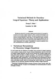
which characterizes the ratio between the distance of the fictitious boundary and real boundary to the geometry center gc of the physical domain. Example 1. First consider steady state heat conduction in nonlinear exponential heterogeneous FGM in the square Ω = (−1, 1) × (−1, 1) (see Fig. 1). In practice, the dependence of the thermal conductivity on the temperature is always chosen as linear, i.e. a( T ) = 1 + µT, where µ is a constant. Therefore, the governing equation of this problem is 2 2 ∑ 2β i xi ∂T ( x, t ) ∂ = 0, x = ( x1 , x2 ) , ∈ Ω (3.3) ∑ ∂xi (1 + µT ) K¯ ij ei=1 ∂x j i,j=1 (
where K¯ =
1 0.5 0.5 4
) ,
β 1 = 0.3,
β 2 = 0.7,
µ=
1 . 2
By Kirchhoff transformation, we obtain µ ΦT = T + T2 , 2
T=ϕ
−1
(ΦT ) =
−1 +
√
1 + 2µΦ T . µ
Then the following transformed governing equation is calculated by the proposed methods as ) 2 ( ∂2 Φ T (x, t) ∂Φ T (x, t) ¯ ¯ K + 2β = 0, x = ( x1 , x2 ) ∈ Ω. (3.4) K i ij ∑ ij ∂xi ∂x j ∂x j i,j=1 The corresponding analytical solution in this example is √ −1 + 1 + 2µΦT (x) , x = ( x1 , x2 ) ∈ Ω, T (x) = µ where Φ T (x) = exp
2 ( λ ( Tx + Ty) ) − ∑ β i xi , τ i =1
(3.5)
(3.6)
528
Z. J. Fu, W. Chen and Q. H. Qin / Adv. Appl. Math. Mech., 4 (2012), pp. 519-542
x2 T T T
K
x1
T Figure 1: Geometry of Example 1 and its boundary conditions.
in which
v (√ )2 ) u (√ u ¯ 12 ¯ 12 ∆ ∆ ¯ −K ¯ −K K K t τ = K¯ 11 + 2K¯ 12 + K¯ 22 , K¯ 11 K¯ 11 √ x1 ∆K¯ x1 K¯ 12 , Ty = − + x2 . Tx = K¯ 11 K¯ 11
It should be mentioned that the corresponding Dirichlet boundary condition is imposed based on the analytical solution. Fig. 2 presents the effect of fictitious boundary parameter d on numerical accuracy in the MFS. It is observed from Fig. 2 that the MFS improves numerical accuracy at the beginning of increasing fictitious boundary parameter d, then rapidly exacerbate numerical accuracy after achieving the optimal parameter d. Moreover, the optimal
Figure 2: Effect of fictitious boundary parameter d on numerical accuracy in the MFS.
Z. J. Fu, W. Chen and Q. H. Qin / Adv. Appl. Math. Mech., 4 (2012), pp. 519-542
529
Figure 3: (a) The condition number of the interpolation matrices and (b) the convergent rates of Example 1 by the present CTM, BKM and MFS with different fictitious boundary parameters (d = 2, 8, 14).
parameter d may decrease with the increasing boundary knot number. Therefore, the fictitious boundary parameter d in the MFS is problem-dependent and significantly affects its numerical accuracy. Fig. 3(a) shows the condition numbers of the corresponding interpolation matrices by the present CTM, BKM and MFS with different fictitious boundary parameter (d = 2, 8, 14). The condition number Cond in Fig. 3(a) is defined as the ratio of the largest and smallest singular value. It is observed from Fig. 3(a) that with increasing boundary points, all the condition numbers grow rapidly and the CTM in particular. This property downplays these boundary collocation methods. There are several ways to handle this ill-conditioning problem, including the domain decomposition method, preconditioning technique based on approximate cardinal basis function, the fast multiple method and regularization methods [25] such as the truncated singular value decomposition (TSVD). This study will use the TSVD to mitigate the effect of bad conditioning in the CTM, MFS and BKM solutions, and the generalized cross-validation (GCV) function choice criterion is employed to estimate an appropriate regularization parameter of the TSVD. Our computations use the MATLAB Regularization tools developed by Hansen [25]. Fig. 3(b) displays the convergent rate of Example 1 by the present CTM, MFS and BKM coupled with the TSVD. It can be seen that the CTM provides the most excellent results among these methods; the BKM has better performance with few interpolation knots than MFS. It is noted that the numerical accuracy of BKM solution improves evidently with modestly increasing boundary knots, but enhances slowly with a relatively large number of nodes. Furthermore, it is observed that the MFS converges more slowly than that of the other two methods, however, when choosing an appropriate parameter d (d = 2) it obtains much better performance than the BKM. Example 2. A functionally graded finite strip with a unidirectional variation of ther-
530
Z. J. Fu, W. Chen and Q. H. Qin / Adv. Appl. Math. Mech., 4 (2012), pp. 519-542
Figure 4: Geometry of Example 2 and its boundary conditions.
mal conductivity, as shown in Fig. 4, is considered [8]. The governing equation is ( ) 2 ( 2 ) ∂T (x, t) ∂ ∑ ∂xi K¯ ij exp ∑ 2βi xi ∂x j i =1 i,j=1
=106 exp
(
2
∑ 2βi xi
i =1
) ∂T (x, t) , ∂t
x = ( x1 , x2 ) ∈ Ω.
(3.7)
The corresponding parameters of thermal conductivity and specific heat are ( ) 17 0 ¯ a( T ) = 1, K = , β 2 = 0. 0
17
Since the thermal conductivity is independent of temperature, i.e. a( T ) = 1, there is no need to use the Kirchhoff transformation in this example. By applying the Laplace transform to Eq. (3.7), we obtain ) 2 ( 2Φ ˜ T (x, p) ˜ T (x, p) ∂ Φ ∂ ˜ T (x, p) = 0, − 106 pΦ ∑ K¯ ij ∂xi ∂x j + 2βi K¯ ij ∂x j i,j=1 x = ( x1 , x2 ) ∈ Ω.
(3.8)
Four different material property constants β 1 = 0, 10, 25, 50 are assumed in numerical computation of a 0.04 × 0.04 square. On the sides parallel to the x2 -axis two different temperatures (Dirichlet condition) are prescribed. One side is kept at T (0, x2 , t) = 0 and the other one has the Heaviside step time function, i.e., T (0.04, x2 , t) = H (t). On the lateral sides of the strip the heat flux (Neumann condition) vanishes. The special case with material property constant β 1 = 0 degenerates to a homogeneous material. The corresponding analytical solution [8] is ( ) ( ) x1 2 ∞ cos (iπ ) iπx1 K¯ 11 i2 π 2 t T (x, t) = + sin exp − 6 , 0.04 π i∑ i 0.04 10 0.042 =1 x = ( x1 , x2 ) ∈ Ω
(3.9)
Z. J. Fu, W. Chen and Q. H. Qin / Adv. Appl. Math. Mech., 4 (2012), pp. 519-542
531
Figure 5: Temperature variation in a finite strip with respect to time (t) at three different locations of Example 2 with β 1 = 0 by the present (a) BKM, (c) CTM and (e) MFS (d = 8); The corresponding error variation by the present (b) BKM, (d) CTM and (f) MFS (d = 8).
which is applied to assess the numerical accuracy of the present three schemes. For the sake of convenience, numerical results are obtained by using the same boundary knots (N = 36) and selecting the appropriate parameter d in the MFS. Fig. 5 presents the temperature and the corresponding error variations at three different points (x1 = 0.01, 0.02, 0.03) along the line x2 = 0.02 by the CTM, BKM and MFS
532
Z. J. Fu, W. Chen and Q. H. Qin / Adv. Appl. Math. Mech., 4 (2012), pp. 519-542
Figure 6: Temperature variation of functionally graded finite strip against time at point (0.01, 0.02) by the present CTM, BKM and MFS (d = 3).
(d = 8), respectively. It can be found from Fig. 5 that all the numerical results of these three methods are in good agreement with the analytical solution, and the CTM and the MFS (d = 8) performs a little bit better than the BKM. Moreover, it is observed from Figs. 5(d) and (f) that the error variations of CTM and MFS (d = 8) are almost the same, which reveals that the error is generated mainly by the Stehfest numerical inversion technique, rather than the CTM and MFS computation. To illustrate the application of the present schemes to the FGM with β 1 = 0, 10, 25, 50. The variation of temperature with time for different material property constant β 1 at point (0.01, 0.02) is present in Fig. 6. It can be found from Fig. 6 that numerical results obtained by the MFS with an appropriate parameter d (d = 3) agree well with both the CTM and BKM results. As expected, it is observed that the temperature at the specific location increases with the increasing of the thermal conductivity, which dues to increasing in the value of β 1 , and the temperature tends to a steady state at long time (t > 60). The corresponding analytical solution for steady state situation (tS ) is taken as T (x, tS ) =
e−2β1 x1 − 1 , e−2β1 ×0.04 − 1
x = ( x1 , x2 ) ∈ Ω.
Fig. 7 displays numerical results obtained by these three methods under stationary or static loading conditions compared with the analytical solution. All the numerical results perform well with the analytical solution at the steady state situation (tS ). Among these three methods, the CTM achieves the best numerical accuracy; the MFS (d = 8) yields similar accuracy with that of the CTM when β 1 is small (β 1 = 0, 10), whereas it becomes worse near the boundary x1 = 0 and 0.04 when β 1 is large (β 1 = 25, 50). It is observed from Figs. 5-7 that the appropriate parameter d in the MFS changes in different examples, which may depend on time levels and material property.
Z. J. Fu, W. Chen and Q. H. Qin / Adv. Appl. Math. Mech., 4 (2012), pp. 519-542
533
Figure 7: Temperature variation along with x1 -axis for functionally graded finite strip under steady state loading conditions in Example 2 by the present (a) BKM, (c) CTM and (e) MFS (d = 8); The corresponding error variation by the present (b) BKM, (d) CTM and (f) MFS (d = 8).
In comparison with LBIEM, Table 1 lists numerical results at different time levels obtained by the present methods and LBIEM [8]. From Table 1, all the numerical results agree well with each other, and they are similar and slight larger than the LBIEM results, except at steady state situation. It should be mentioned that the numerical solutions displayed from Figs. 4 and 5 in the literature [8] probably have certain error to
534
Z. J. Fu, W. Chen and Q. H. Qin / Adv. Appl. Math. Mech., 4 (2012), pp. 519-542 Table 1: Comparison of LBIEM* and the proposed methods at β 1 = 25, x1 = 0.01.
t LBIEM BKM CTM MFS (d = 8) Exact
10 0.1871 0.1915 0.1914 0.1914 /
20 0.3281 0.3694 0.3686 0.3686 /
30 0.3800 0.4286 0.4277 0.4277 /
40 0.3986 0.4471 0.4468 0.4468 /
50 0.4019 0.4523 0.4529 0.4529 /
60 0.4053 0.4553 0.4547 0.4547 /
Infinite 0.4581 0.4553 0.4552 0.4552 0.4551
(* the LBIEM results were obtained from Figs. 4 and 5 in reference [8].)
practical computing results produced by LBIEM. Different treatments of time domain may be the main reason causing the discrepancy. Example 3. A functionally graded finite strip with nonlinear thermal conductivity and specific heat is considered in this example (see Fig. 8). The governing equation is ( ) 2 ( 2 ) ∂T (x, t) ∂ ∑ ∂xi (1 + µT ) K¯ ij exp ∑ 2βi xi ∂x j i,j=1 i =1
= (1 + µT ) exp
(
2
∑ 2βi xi
i =1
(
where K¯ =
) ∂T (x, t) , ∂t
x = ( x1 , x2 ) ∈ Ω,
)
5 0 , 0 5
β 1 = 0,
β 2 = 1.5,
µ=
(3.10)
1 . 4
A unit square is considered in numerical calculation. Two different temperatures (Dirichlet condition) are prescribed on the physical boundaries paralleling to the x1 axis. √ One side is kept at T ( x1 , 0, t) = 0 and the other is maintained at T ( x1 , 1, t) = 4 51 − 4. The remaining two boundaries are insulated (zero normal flux). Making use of Kirchhoff transformation, we obtain √ −1 + 1 + 2µΦT µ 2 −1 . ΦT = T + T , T = ϕ (Φ T ) = 2 µ Then the following Kirchhoff-transformed governing equation can be obtained 2
∑
i,j=1
(
∂2 Φ T (x, t) ∂Φ (x, t) K¯ ij + 2β i K¯ ij T ∂xi ∂x j ∂x j
)
=
∂Φ T (x, t) , ∂t
x = ( x1 , x2 ) ∈ Ω.
(3.11)
Furthermore, applying the Laplace transform to Eq. (3.11), we have 2
∑
i,j=1
(
˜ T (x, p) ˜ (x, p) ∂2 Φ ∂Φ K¯ ij + 2β i K¯ ij T ∂xi ∂x j ∂x j
x = ( x1 , x2 ) ∈ Ω.
) ˜ T (x, p) = 0, − pΦ (3.12)
Z. J. Fu, W. Chen and Q. H. Qin / Adv. Appl. Math. Mech., 4 (2012), pp. 519-542
535
Figure 8: Geometry of Example 3 and its boundary conditions.
The analytical solution of this example [7] is √ −1 + 1 + 2µΦT (x, t) T (x, t) = , µ
x = ( x1 , x2 ) ∈ Ω,
(3.13)
where Φ T (x, t) = 100 in which
∞ 1 − e−2β2 x2 − β 2 x2 −(i2 π 2 + β22 )K¯ 11 t + A sin iπx e , ( ) n 2 ∑ 1 − e−2β2 i =1
] [ 200e β2 1 + e−2β2 − iπ cos (iπ ) . An = − 2 β 2 sin (iπ ) 1 − e−2β2 β 2 + i2 π 2
(3.14)
(3.15)
For the sake of convenience, numerical results are obtained by using the same boundary knots (N = 36) and selecting the appropriate parameter d(d = 2) in the MFS. The temperature profiles and the corresponding error variations of Example 3 along with x2 -axis are plotted on Fig. 9 for various times t = 0.002, 0.01, 0.02, 0.05, 0.1. Numerical results of these three methods agree very well with the analytical solutions, except the BKM results at x2 = 0, t = 0.1. Table 2 shows numerical accuracy of Example 3 with different time levels by the present CTM, BKM and MFS (d = 2). It can be seen from Table 2 that all these three Table 2: Numerical accuracy (Rerr) of the present CTM and BKM with various times.
t BKM CTM MFS (d = 2)
0.01 2.635 e-3 2.915 e-3 2.923 e-3
0.02 7.903 e-4 7.589 e-4 7.583 e-4
0.1 4.092 e-4 4.812 e-4 4.810 e-4
1 3.020 e-5 6.743 e-6 6.688 e-6
536
Z. J. Fu, W. Chen and Q. H. Qin / Adv. Appl. Math. Mech., 4 (2012), pp. 519-542
Figure 9: Temperature profile of Example 3 along with x2 -axis at different time levels by the present (a) BKM, (c) CTM and (e) MFS (d = 2); The corresponding error variation by the present (b) BKM, (d) CTM and (f) MFS (d = 2).
methods yield good accuracy, and with increasing time the higher accuracy is obtained. It should be mentioned that, for the sake of convenience, this study chooses the same boundary knots (N = 36) and selects the appropriate parameter d in the MFS. Therefore, the MFS results may be improved via increasing boundary knot number and selecting the optimal parameter d. Despite great efforts for decades, determining
Z. J. Fu, W. Chen and Q. H. Qin / Adv. Appl. Math. Mech., 4 (2012), pp. 519-542
537
the optimal parameter d is still an open issue, one may find some related techniques in the literatures [15, 17, 26–28].
4 Conclusions This paper presents the T-complete functions, singular fundamental solutions and nonsingular RBF general solutions for two-dimensional heat conduction problems in exponential FGMs by employing the Kirchhoff transformation and coordinate transformations. Laplace transform technique is applied to handle the time variable and the Stehfest numerical Laplace inversion is applied to retrieve time-dependent solutions. The collocation Trefftz method, method of fundamental solution and boundary knot method in conjunction with the truncated singular value decomposition is used for heat conduction analysis in nonlinear FGMs. In comparison with LBIEM and analytical solutions, numerical results demonstrate that the proposed CTM, MFS and BKM are competitive boundary collocation numerical method for the solution of steady state and transient heat conduction in nonlinear FGMs, which is mathematically simple, easy-to-program, meshless, highly accurate and integration-free. From the present numerical experiments, some conclusions are achieved as follows: 1. The CTM performs best among these three methods. However, its condition number is exceedingly huge and the terms of T-complete functions should be carefully chosen to obtain desired results [29]. Moreover, it is difficult to derive and implement high-dimension T-complete functions. This issue is still under study. 2. The BKM converges much faster than the MFS with few boundary knots (e.g., N < 50), but the accuracy cannot be improved with further increasing the number of boundary nodes. Moreover, it requires deriving the corresponding RBF general solution of the governing equation under consideration. 3. The MFS converges more slowly than the CTM and the BKM. However, when choosing an appropriate parameter d, it does far better than the BKM. The fictitious boundary parameter d is problem-dependent and affects the numerical accuracy remarkably. Therefore, determining this optimal parameter d is a crucial task and remains an open issue, and some related techniques can be found in the literatures [15, 17, 26–28].
Acknowledgments We thank the anonymous reviewers of this paper for their very helpful comments and suggestions to significantly improve the academic quality of this paper. The work described in this paper was supported by National Basic Research Program of China (973 Project No. 2010CB832702), and the R&D Special Fund for Public Welfare Industry (Hydrodynamics, Grant No. 201101014), National Science Funds for
538
Z. J. Fu, W. Chen and Q. H. Qin / Adv. Appl. Math. Mech., 4 (2012), pp. 519-542
Distinguished Young Scholars (Grant No. 11125208). The first author would like to thank Hohai University Training Program for Excellent Doctoral Dissertation (Grant No. 2011B14814), Jiangsu Province Graduate Students Research and Innovation Plan (Grant No. CX10B 203Z) for financial support.
A
The derivation of T-complete functions
Step 1: To simplify the expression of Eq. (2.8) (transient) or Eq. (2.13) (steady state), 2 set Φ T = Ψe− ∑i=1 βi xi . Then Eq. (2.8) or Eq. (2.13) can be rewritten as follows: ) ( 2 ( 2 ) ∂Ψ ( x ) x = ( x1 , x2 ) ∈ Ω, (A.1) ∑ K¯ ij ∂xi ∂x j − λ2 Ψ(x) exp − ∑ βi xi = 0, i,j=1 i =1 in which
v u 2 u λ = t∑
¯ ∑ βi K¯ ij β j + ρ¯ cp
v u 2 u λ = t∑
∑ βi K¯ ij β j
2
(transient case) ,
i =1 j =1
or
2
(steady state case).
i =1 j =1
Since
( 2 ) exp − ∑ β i xi > 0, i =1
the T-complete functions of Eq. (A.1) are equal to those of anisotropic modified Helmholtz equation. Step 2: To find the solution of Eq. (A.1), we set 1 √ 0 ( ) ( ) K¯ 11 y1 x1 √ = , (A.2) K¯ 11 x2 y2 −K¯ 12 √ √ ∆K¯ K¯ 11 ∆K¯ where
2 > 0. ∆K¯ = det (K¯ ) = K¯ 11 K¯ 22 − K¯ 12
It follows from Eq. (A.1) that ) ( 2 ∂2 Ψ ( y ) 2 ∑ ∂yi ∂yi −λ Ψ (y) = 0, i =1
y = (y1 , y2 ) ∈ Ω.
(A.3)
Hence we have the T-complete solutions for Eq. (A.1) in the form [18, 23] I0 (λr ) , Im (λr ) cos (mθ ) , Im (λr ) sin (mθ ) ,
m = 1, 2, · · · , (r, θ ) ∈ Ω,
(A.4)
Z. J. Fu, W. Chen and Q. H. Qin / Adv. Appl. Math. Mech., 4 (2012), pp. 519-542
539
√ where r = y21 + y22 , θ = arctan(y2 /y1 ), and Im denotes the m-order modified Bessel function of first kind. Therefore, the T-complete functions of Eqs. (2.8) or (2.13) is represented as ( 2 ) I0 (λr ) exp − ∑ β i xi ,
( 2 ) Im (λr ) cos (mθ ) exp − ∑ β i xi ,
i =1
i =1
( ) Im (λr ) sin (mθ ) exp − ∑ β i xi , 2
m = 1, 2, · · · .
(A.5)
i =1
B The derivation of singular fundamental solution and nonsingular RBF general solution Step 1: To simplify the expression of Eq. (2.8) (transient) or Eq. (2.13) (steady state), let ( 2 ) Φ T = Ψexp − ∑ β i ( xi + si ) . i =1
Eq. (2.8) or Eq. (2.13) can then be rewritten as follows: ) ( 2 ( 2 ) ∂Ψ ( x ) 2 ¯ − λ Ψ ( x ) exp − ∑ β i ( xi + si ) = 0, K ∑ ij ∂xi ∂x j i,j=1 i =1 where
v u 2 u λ = t∑
x = ( x1 , x2 ) ∈ Ω,
(B.1)
2
¯ ∑ βi K¯ ij β j + ρ¯ cp
(transient case) ,
i =1 j =1
or
v u 2 u λ = t∑
2
∑ βi K¯ ij β j
(steady state case).
i =1 j =1
Since
( 2 ) exp − ∑ β i ( xi + si ) > 0, i =1
the singular fundamental solution and nonsingular RBF general solutions of Eq. (B.1) are equal to those of anisotropic modified Helmholtz equation. Step 2: To transform the anisotropic equation (B.1) into isotropic one, we set 1 √ 0 ( ) ( ) K¯ 11 y1 x1 √ = , (B.2) K¯ 11 x2 y2 −K¯ 12 √ √ ∆K¯ K¯ 11 ∆K¯
540
Z. J. Fu, W. Chen and Q. H. Qin / Adv. Appl. Math. Mech., 4 (2012), pp. 519-542
2 > 0. It follows from Eq. (B.1) that where ∆K¯ = det(K¯ ) = K¯ 11 K¯ 22 − K¯ 12
(
∂2 Ψ ( y ) ∑ ∂yi ∂yi −λ2 Ψ (y) i =1 2
)
= 0,
y = (y1 , y2 ) ∈ Ω.
(B.3)
Therefore, Eq. (B.3) is the isotropic modified Helmholtz equation, the corresponding singular fundamental solution and nonsingular RBF general solutions can be found in [19, 24]. Then the singular fundamental solutions and nonsingular RBF general solutions of Eq. (B.1) are obtained by inverse transformation (B.2), respectively, u F (x, s) = − uG (x, s) = −
2π
1 √
2π
∆K¯
1 √
∆K¯
K0 (λR) ,
(B.4)
I0 (λR) ,
(B.5)
in which x = ( x1 , x2 ), s = (s1 , s2 ) are collocation points and source points, respectively, and v u 2 2 u R = t ∑ ∑ ri K¯ −1 r j , r1 = x1 − s1 , r2 = x2 − s2 , i =1 j =1
ij
I0 , K0 denotes the zero-order modified Bessel function of first and second kind. Finally, by implementing the variable transformation ( 2 ) Φ T = Ψexp − ∑ β i ( xi + si ) , i =1
singular fundamental solutions and nonsingular RBF general solutions of Eq. (2.8) or Eq. (2.13) are in the following form, respectively, u F (x, s) = −
( 2 ) K0 (λR) √ exp − ∑ β i ( xi + si ) , 2π ∆K¯ i =1
(B.6)
uG (x, s) = −
( 2 ) I0 (λR) √ exp − ∑ β i ( xi + si ) . 2π ∆K¯ i =1
(B.7)
References [1] F. E RDOGAN, Fracture mechanics of functionally graded materials, Compos. Eng., 5 (1995), pp. 753–770. [2] Y. K OIKE , High-bandwidth graded-index polymer optical fibre, Polym., 32 (1991), pp. 1737– 1745. [3] J. TANI AND G. R. L IU , SH surface waves in functionally gradient piezoelectric plates, JSME Int. J., Ser. A, 36 (1993), pp. 152–155.
Z. J. Fu, W. Chen and Q. H. Qin / Adv. Appl. Math. Mech., 4 (2012), pp. 519-542
541
[4] W. P OMPE , H. W ORCH , M. E PPLE , W. F RIESS , M. G ELINSKY, P. G REIL , U. H EMPEL , D. S CHARNWEBER AND K. S CHULTE, Functionally graded materials for biomedical applications, Mater. Sci. Eng. A, 362 (2003), pp. 40–60. [5] J.H. K IM AND G. H. PAULINO , Isoparametric graded finite elements for nonhomogeneous isotropic and orthotropic materials, J. Appl. Mech., 69 (2002), pp. 502–514. [6] A. S UTRADHAR AND G. H. PAULINO, The simple boundary element method for transient heat conduction in functionally graded materials, Comput. Meth. Appl. Mech. Eng., 193 (2004), pp. 4511–4539. [7] A. S UTRADHAR , G. H. PAULINO AND L. J. G RAY, Transient heat conduction in homogeneous and non-homogeneous materials by the Laplace transform Galerkin boundary element method, Eng. Anal. Bound. Elem., 26 (2002), pp. 119–132. [8] J. S LADEK , V. S LADEK AND C. Z HANG, Transient heat conduction analysis in functionally graded materials by the meshless local boundary integral equation method, Comput. Mater. Sci., 28 (2003), pp. 494–504. [9] V. S LADEK , J. S LADEK , M. TANAKA AND C. Z HANG, Transient heat conduction in anisotropic and functionally graded media by local integral equations, Eng. Anal. Bound. Elem., 29 (2005), pp. 1047–1065. [10] J. S LADEK , V. S LADEK , C. L. TAN AND S. N. ATLURI, Analysis of transient heat conduction in 3D anisotropic functionally graded solids by the MLPG, CMES-Comput. Model. Eng. Sci., 32 (2008), pp. 161–174. [11] H. WANG , Q. H. Q IN AND Y. L. K ANG, A meshless model for transient heat conduction in functionally graded materials, Comput. Mech., 38 (2006), pp. 51–60. [12] L. M ARIN AND D. L ESNIC , The method of fundamental solutions for nonlinear functionally graded materials, Int. J. Solids Struct., 44 (2007), pp. 6878–6890. [13] J. H. Z HENG , M. M. S OE , C. Z HANG AND T. W. H SU, Numerical wave flume with improved smoothed particle hydrodynamics, J. Hydro. B., 22 (2010), pp. 773–781. [14] T. B ELYTSCHKO , Y. K RONGAUZ , D. O RGAN , M. F LEMING AND P. K RYSL, Meshless methods: An overview and recent developments, Comput. Meth. Appl. Mech. Eng., 139 (1996), pp. 3–47. [15] G. FAIRWEATHER AND A. K ARAGEORGHIS, The method of fundamental solutions for elliptic boundary value problems, Adv. Comput. Math., 9 (1998), pp. 69–95. [16] C. S. C HEN , A. K ARAGEORGHIS AND Y. S. S MYRLIS, The Method of Fundamental Solutions - A Meshless Method, Dynamic Publishers, (2008). [17] G. FAIRWEATHER , A. K ARAGEORGHIS AND P. A. M ARTIN, The method of fundamental solutions for scattering and radiation problems, Eng. Anal. Bound. Elem., 27 (2003), pp. 759– 769. [18] Z. C. L I , T. T. L U , H. T. H UANG AND A. H. D. C HENG, Trefftz, collocation, and other boundary methods - a comparison, Numer. Meth. Part. D. E., 23 (2007), pp. 93–144. [19] W. C HEN AND M. TANAKA, A meshless, integration-free, and boundary-only RBF technique, Comput. Math. Appl., 43 (2002), pp. 379–391. [20] D. L. Y OUNG , C. C. T SAI , K. M URUGESAN , C. M. FAN AND C. W. C HEN , Time-dependent fundamental solutions for homogeneous diffusion problems, Eng. Anal. Bound. Elem., 28 (2004), pp. 1463–1473. [21] L. C AO , Q. H. Q IN AND N. Z HAO, An RBF-MFS model for analysing thermal behaviour of skin tissues, Int. J. Heat Mass Tran., 53 (2010), pp. 1298–1307. [22] D. P. G AVER, Observing stochastic processes and approximate transform inversion, Oper. Res., 14 (1966), pp. 444–459. [23] Z. J. F U , Q. H. Q IN AND W. C HEN , Hybrid-Trefftz finite element method for heat conduction
542
Z. J. Fu, W. Chen and Q. H. Qin / Adv. Appl. Math. Mech., 4 (2012), pp. 519-542
in nonlinear functionally graded materials, Eng. Comput., 28 (2011), pp. 578–599. [24] Z. J. F U , W. C HEN AND Q. H. Q IN , Boundary Knot method for heat conduction in nonlinear functionally graded material, Eng. Anal. Bound. Elem., 35 (2011), pp. 729–734. [25] P. H ANSEN, Regulazation tools: a Matlab package for analysis and solution of discrete ill-posed problems, Numer. Algorithms, 6 (1994), pp. 1–35. [26] A. K ARAGEORGHIS, A practical algorithm for determining the optimal pseudo-boundary in the method of fundamental solutions, Adv. Appl. Math. Mech., 1 (2009), pp. 510–528. [27] A. P. C ISILINO AND B. S ENSALE, Application of a simulated annealing algorithm in the optimal placement of the source points in the method of the fundamental solutions, Comput. Mech., 28 (2002), pp. 129–136. [28] R. N ISHIMURA , K. N ISHIMORI AND N. I SHIHARA, Determining the arrangement of fictitious charges in charge simulation method using genetic algorithms, J. Electrostat., 49 (2000), pp. 95–105. [29] Q. H. Q IN, The Trefftz Finite and Boundary Element Method, WIT Press, Southampton (2000).