JLMN-Journal of Laser Micro/Nanoengineering Vol. 9, No. 2, 2014
Three Phase Boundary Enhancement in SOFC Anodes by Applying Laser Drilling Technique Mindaugas MACIULEVIČIUS*1, Brigita ABAKEVIČIENĖ*2,3, Edvinas NAVICKAS*2, Mindaugas GEDVILAS*1, Sigitas TAMULEVIČIUS*2 and Gediminas RAČIUKAITIS*1 *1
Department of Laser Technologies, Center for Physical Science and Technology, Savanoriu Ave. 231, LT – 02300 Vilnius, Lithuania E-mail:
[email protected] *2 Institute of Materials Science of Kaunas University of Technology, Savanoriu Ave. 271, LT – 50131 Kaunas, Lithuania *3 Department of Physics, Kaunas University of Technology, Studentu str. 50, LT - 51368 Kaunas, Lithuania Laser drilling is one of the promising techniques to modify layers, but the interaction of composite materials with the laser radiation is non-trivial and hardly predictable. In this work, the experimental study of laser processing, that was applied to enhance porosity and thereby the length of three-phase boundary of plasma-sprayed YSZ-NiO-Ni cermet layer, is presented. For a better understanding of radiation interaction with composite materials the drilling was accomplished with different laser irradiation doses (1.57–4.2×10⁵ J/cm2) with two different laser systems. The diameter and shape of the laser drilled holes were analyzed with a scanning electron microscope (SEM) while changes of the elemental composition of the spatter versus conditions of irradiation were defined by energy dispersive X-ray analysis (EDX). It has been found that geometrical dimensions of the drilled holes as well as composition of the spatter vary non-monotonously with the laser irradiation dose. The threshold values of the laser irradiation dose for the optimal diameter of holes are reported.
DOI: 10.2961/jlmn.2014.02.0016
Keywords: SOFC, YSZ-NiO-Ni cermets, plasma spray, laser drilling Laser micro-structuring techniques can be used to improve the porosity and length of the three-phase boundary of anode. Laser ablation is a non-contact, precise and efficient technique [11] applicable to form the holes in various ceramics and metal coatings [12-15]. Laser drilling technique has been already used for drilling of green ceramics and ceramic coatings [3, 16-19]. One of the ways to improve ceramics drilling efficiency is to use additional laser radiation absorbing pigments. In ref. [18] the absorbance of laser irradiation was improved by including organic matter (acrylic polymers). It was reported that the laser drilling procedure was much faster when organic matter was used, since samples after sintering were less absorbing. The aim of this research was to synthesize YSZ-NiO-Ni coatings by the plasma-spray method, accomplish laser drilling of the formed coatings to produce micron size channels in YSZ-NiO-Ni coatings, which will increase the porosity of coatings and the length of the three-phase boundary of coating. The plasma sprayed coatings were treated using different parameters with two industrial laser Nd:YVO4 and Nd:YAG systems working at the wavelength of 532 nm. The nanosecond lasers were chosen due to their excellent beam focus ability, precision in machining large areas and accuracy in the iteration of the process. Similar nanosecond laser working at the repetition rate of tens of kilohertz has shown successful results of ablation of ceramics in the previous work of J. Gurauskis et al. [18]. The irradiation at wavelength of 532 nm instead of 1064 nm was chosen for better material absorption of laser radiation. Shape and linear dimensions of the drilled holes as well as changes in the elemental composition of the spatter were
1. Introduction 2. Solid oxide fuel cells (SOFC) are one of the most promising energy generation alternatives because of their high efficiency. Composite coatings of yttria-stabilized zirconia (YSZ) with nickel have high potential for application as electrodes for SOFC and for solid oxide electrolysis cells (SOEC) [1], and due to the highest Ni activity in comparison with other metals (e.g. Co Pt, Pd), they are potentially suitable for the anode. In both cases, i.e. SOFC and SOEC, the electrochemical reaction in the electrode takes place at the three-phase boundary (TPB), which is defined as the collection of sites where electrolyte, the electron conducting metal phase and the gas phase all come together. The efficiency of anode mainly depends on the length of TPB in the formed coating. The composite YSZ-NiO-Ni coatings can be prepared by various methods such as gel-casting [2], magnetron sputtering [3], electro-deposition [4] or electron beam evaporation [5]. In the present research, the high deposition rate plasma-spray technique was applied to deposit YSZNiO-Ni coatings. Coatings prepared by the plasma-spray method, contrary to many others, do not require any additional calcination and show microstructure stability during annealing [6]. Finally, the plasma-spray method is also promising for SOFC anode application due to the ability to synthesize coatings with the high porosity [7, 8, 9], which is a necessary attribute for good gas permeability. Porosity of the composite coatings can be controlled by including various additives, e.g. carbon black [10], but in this case the third insulating phase is inserted, which can worsen mechanical and electrical properties of the coating.
169
JLMN-Journal of Laser Micro/Nanoengineering Vol. 9, No. 2, 2014
Table 1 Specifications of the used lasers. Laser NL220 Active medium Nd:YAG Wavelength, nm 532 Pulse duration, ns 25 Max pulse energy, mJ 1.6 Repetition rate, kHz 0.5 Mode structure TEM00 Spot size on sample, μm 28
analyzed to define a threshold of laser irradiation energy for effective drilling. For a better understanding of radiation interaction with the composite material the drilling was accomplished with different laser irradiation doses using two different laser systems. The diameter and shape of the drilled holes were analyzed by SEM while changes of the elemental composition of the spatter versus conditions of irradiation were defined by EDX.
NL15100 Nd:YVO4 532 10 0.26 10 TEM00
28
The effect of laser parameters on the hole shape and diameter was determined from the laser drilling experiments using different laser irradiation doses (1.57–4.2×10⁵ J/cm2) and different count of pulses (1–104). The microstructure of the synthesized coating was examined by the X-ray diffraction method (XRD). The XRD analysis was done with a DRON 3.0 diffractometer using θ–2θ Bragg-Brentano geometry and Cu Kα radiation (λ = 0.15 nm). Elemental composition of the coating (before and after laser drilling) was determined by EDX. Surface morphology and EDX analysis of the samples were done with a SEM Quanta 200 (FEI). The area and shape of the drilled holes were evaluated by image-analysis software ImageJ using pictures recorded by both the SEM and the optical microscope. The shape of holes was evaluated with a confocal microscope Zeiss Confocal LSM510. The surface roughness of plasma sprayed YSZ-NiO-Ni coatings was measured with a surface roughness tester TR200.
3. Experimental procedure Mixture of yttria-stabilized zirconia (YSZ) and nickel oxide (NiO) powders was plasma sprayed on alumina substrates. YSZ powder (H. C. Starck) with a diameter less than 40 μm and NiO powder (MERCK) with a diameter of approximately 6 μm were used. The mixture of YSZ and NiO was prepared by stirring a mixture of powders (60 wt.% YSZ and 40 wt.% of NiO). The equipment used for the arc plasma generation and deposition of YSZ-NiONi coatings consisted of a plasma gun SG-100 (Miller Thermal Inc.) mounted in a water-cooled vacuum chamber, a cooling substrate holder and a powder feeder. Argon gas was used for plasma forming and as a carrier gas. The argon gas flow rate was 25 l/min, current of the plasma torch was 500 A at voltage of 35 V. The powder feed rate was 10 g/min. The stand-off distance of the sample from a plasma gun was 30 cm. Pressure in the chamber during arc plasma spray was 1300 Pa. The thickness of synthesized coating was evaluated with an optical microscope from cross-section photos and it led to a thickness of 20 μm. The open porosity of coatings on the alumina substrate was 7.9 %. More experimental details on the synthesis of coatings can be found elsewhere [8, 20]. The experimental setup for laser treatment of deposited coating is given in Fig. 1.
4. Experimental results Fig. 2 presents XRD analysis results of the substrate and arc plasma sprayed coatings. The typical peaks for the alumina substrate and for the YSZ-NiO-Ni coating are marked. The crystalline cubic phase YSZ and NiO as well as Ni, which originates from decomposition of NiO, can be identified in the XRD patterns. This type of coatings can be described as YSZ-NiO-Ni cermets coating with metallic conductivity – the necessary attribute for the SOFC anode [1].
Fig. 1 Experimental setup for laser processing.
The beam delivery path included: the attenuator, the beam expander with a variable magnification factor and collimation option and focusing objective mounted on the z axis. The sample was placed on the xy positioning stage. The two different diode-pumped lasers NL220 and NL15100 (Ekspla Ltd.) were used in the experiments within the same experimental setup. The parameters of the lasers are given in Table 1.
Fig. 2 XRD patterns of the substrate and synthesized coating, 1 – alumina substrate, 2 – YSZ-NiO-Ni cermets coating.
According to the EDX measurements, the coatings mainly consist of Ni or NiO (nickel – 49.51 norm. wt. %, oxygen – 37.14 norm. wt. %, zirconium – 6.8 norm. wt. %, yttrium – 0.9 norm. wt. %). The initial mixture of powder consists of YSZ with much larger diameter particles than the NiO par170
JLMN-Journal of Laser Micro/Nanoengineering Vol. 9, No. 2, 2014
ticles, which may lead to non-uniform distribution of the elements. The laser drilling was performed on the same sample by varying the number of pulses and applied power and the period between the drilled holes was 100 μm.
Diameter squared, D2 [µm2]
1400
4.1 Processing by using the NL220 laser According to the experimental results, the area of the drilled holes evaluated by the ImageJ analysis software after the initial increase further decreased with the number of pulses (Fig. 3).
1200 1000 800
N=10000
N=1000
600 400 200 0
1
10
100
1000
Peak laser fluence, F0 [J/cm2]
Fig. 5 Variation of the holes diameter as a function of the peak laser fluence processed by using the NL220 laser at the high number of laser pulses.
After the experiments with the high pulse energy and low repetition rate laser NL220 it was switched to the high repetition rate low pulse energy laser NL15100 (Table 1) because using low pulse energy and thousands of laser pulses showed a better ablation quality. The high repetition was chosen in order to shorten the overall processing time. 4.2 Processing by using the NL15100 laser The typical cross-sections, representing the shape of drilled holes, are shown in Fig. 6.
Fig. 3 SEM images of holes drilled with the varied number of pulses and peak laser fluence by using nanosecond laser NL220.
a)
The diameter of the hole as one can see in the SEM picture varies non-linearly. Lower irradiation doses (D = N∙Φ, where N – number of pulses, Φ – laser fluence) lead to initial formation of the hole, while at higher D re-sputtering process takes place and the spatter starts to close the hole. The hole diameter versus peak laser fluence in the pulse are given in Fig. 4 and Fig. 5.
b)
c)
Fig. 6 Confocal microscopy cross-sections profiles of the holes drilled by using the NL15100 laser. Irradiation doses: a) – 9.3 J/cm2; b) – 82 J/cm2; c) – 641 J/cm2. The surface roughness (RMS) of the plasma sprayed YSZ-NiO-Ni coatings was 1.3 µm
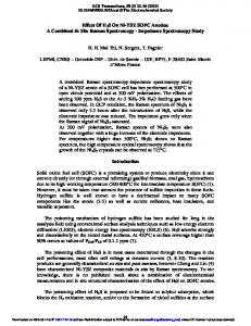
Composition changes of the spatter versus conditions of irradiation (different laser fluence and number of pulses) defined by the EDX analysis is presented in Fig. 7.
Diameter squared, D2 [µm2]
2000 1500
N = 10
1000
N = 100
500 0
1
10
100
Laser fluence, Φ0 [J/cm2]
Fig. 4 Variation of the holes diameter as a function of the peak laser fluence processed by using the NL220 laser at the low number of laser pulses.
Fig. 7 Elemental composition of the spatter as a function of the laser power density.
171
JLMN-Journal of Laser Micro/Nanoengineering Vol. 9, No. 2, 2014
material are expected to be deposited at the edges of the holes. This is represented in the model sketch (Fig. 9).
Fig. 9 Model of laser drilling of holes.
This model is confirmed by the EDX analysis of composition of the spatter. One can see (Fig. 7) that the nickel content obviously decreases with the increase of fluence, meanwhile the concentration of alumina (substrate material) increases – irradiation step by step produced a hole in the coating and material of the substrate appeared on the top of the coating. Even for a low irradiation dose (4 J/cm2) alumina was registered on the surface. The alumina concentration increased onto the coating surface, because the coating was completely drilled through and further irradiation of the samples led to the drilling of the alumina substrate. The deposition of alumina onto the surface of coating resulted in the increase of the oxygen concentration onto the surface (Fig. 7) with the irradiation dose. Thus, the presence of alumina onto the surface can be treated as indirect evidence of the effective via drilling. As can be seen in Fig. 7 nickel, oxygen and aluminum concentrations on the surface reach the equilibrium values at 50 J/cm2 (and higher) irradiation dose. This fact demonstrates that the effective drilling of 20 μm thick YSZ-NiO-Ni coatings stops with the 50 J/cm2 irradiation dose. Further irradiation affects the substrate and at the irradiation dose over 50 J/cm2 only slight changes of elemental composition can be observed. Nevertheless from the EDX mapping (Fig. 8) it is obviously seen that in the melted coating area YSZ and Ni/NiO elements are uniformly distributed and may compose a two-phase boundary (ionic/electronic conductor) [1]. Almost all the drilled holes independently of the applied laser fluence and the number of pulses were irregular in shape (Fig. 3). The irregular shape of the drilled holes (as it was observed in [22] as well) basically can be explained by the different light absorption by elements of the cermet coating. The absorbance of Ni is higher and the melting temperature is lower than that for the rest of the components. This can also be reason that the rate of energy deposition was found to be an important factor in shape control of the drilled holes. These hole-shape variations can be related to the compositional changes of the irradiated regions located near the edges of the holes (or craters produced by the laser beam) as well as surface roughness.
Fig. 8 Mapping of elemental composition was accomplished of the melted area in a marked square in SEM photo. Mapping photos of elemental composition represent Ni/NiO and ZrO elemental distribution. Processing was done by using the NL15100 laser.
The increase in fluence during laser irradiation led to the decrease of the nickel amount in the spatter layer. One can note that applying the irradiation dose higher than 8 J/cm2 resulted in the evaporation and ejection of the melted material from the bottom part of the coating. At the higher irradiation doses one can note an increase of alumina (substrate material) at the edges of the holes. The EDX mapping results are presented in Fig. 8. The EDX mapping analysis was done on the marked area of the SEM image. The elemental distribution on the surface of Ni/NiO (upwards) and ZrO (hereunder) is presented. The elemental concentration in the EDX mapping photos is correlated with a grey scale – the lighter areas in the photos represent higher concentration of the element. 5. Results and discussion As it was presented in the experimental part, the holes in the YSZ-NiO-Ni coatings were produced applying different laser parameters (the same laser fluence, but different amount of pulses and the same count of pulses, but different laser fluence). In both cases the same dose of irradiation was collected, but with a different impact duration. In both cases it was observed that after the initial increase, the hole diameter further decreased with the increase of the irradiation dose (Fig. 3). The values of the hole area, produced with the irradiation dose lower than 50 J/cm2, are widely dispersed. Due to the low absorbance low irradiation fluencies (6 J/cm2) were measured and analyzed by means of SEM and “ImageJ”. One should note that the area of the holes drilled with the higher irradiation dose demonstrates a clear tendency to decrease. The dispersion of the hole area at lower irradiation doses can be explained by the surface roughness effect. At lower intensities of laser irradiation (and corresponding longer time of exposure) due to the thermal mechanism [18, 19] a larger surface of coating is affected. While at the higher irradiation doses, deeper layers of the coatings are affected and resputtering effects come into play, the ejected material is deposited on the edges of the holes [21] resulting in the decrease of the area of the drilled hole. The holes in the experiment were produced at ambient atmosphere pressure; therefore sputtered droplets of the
6. Conclusions In conclusion, YSZ-NiO-Ni porous coatings (20 μm thickness) were synthesized onto alumina substrates by the plasma spray method. It has been shown that laser drilling can be applied for structuring of the YSZ-NiO-Ni cermets coating. The critical laser irradiation dose (8 J/cm2) was found to be necessary for production vias in the coating. A further increase of the laser irradiation energy leads to the decrease of the effective hole area due to re-sputtering effect and ejection of the material from the deep to the top 172
JLMN-Journal of Laser Micro/Nanoengineering Vol. 9, No. 2, 2014
layer of the coating. The laser micro-structuring technique enables enhancement of the porosity of coating which determines the increment of the three-phase boundary. Acknowledgements This research was funded by a grant (No. ATE-09/2012) from the Research Council of Lithuania. References [1] M. Liang, B. Yu, M. Wen, J. Chen, J. Xu and Y. Zhai: J. Power Sources, 190, (2009) 341-345. [2] M. Rieu, P. Lenormand, P.J. Panteix and F. Ansart: Surf. Coat. Techol., 203, (2008) 893-896. [3] D. Guo, K. Cai, J. Yang and Y. Huang: J. Eur. Ceram. Soc., 23, (2003) 1263-1267. [4] E. Tondo, M. Boniardi, D. Cannoletta and M. D’Elia: Electrodeposition of NiO/YSZ from hydroalcoholic solutions containing Chitosan, Surf. Coat. Techol., 203, (2009) 3427-3434. [5] B. Meng, Y. Sun, X.D. He and J.H. Peng: Thin Solid Films, 517, (2009) 4975-4978. [6] K. Brinkienė, R. Kėželis, A. Baltušnikas and V. Mėčius: Materials Science (Medžiagotyra), 9, (2003) 387-390. [7] Kucuk, C. C. Berndt, U. Senturk and R. S. Lima: Materials Science and Engeenering, A284, (2000) 41-50. [8] T. Grinys, S. Tamulevičius, I. Prosyčevas and Š. Meškinis: Polym., 4, (2007) S181-S184. [9] F. Rousseau, S. Awamat, M. Nikravech, D. Morvan and J. Amouroux: Surf. Coat. Technol., 202, (2007) 1226-1230. [10] J.H. Yu, G.W. Park, S. Lee and S.K. Woo: J. Power Sources, 163, (2007) 926-932. [11] G. Račiukaitis, M. Brikas, P. Gečys, B. Voisiat and M. Gedvilas: J. Laser Micro/Nanoeng., 4, (2009) 186-191. [12] X.D. Wang, A. Michalowski, D. Walter, S. Sommer, M. Kraus, J.S. Liu and F. Dausinger: Opt. Laser Technol., 41, (2009) 148-153. [13] M. Maciulevičius, M. Gedvilas, B. Abakevičienė, S. Tamulevičius and G. Račiukaitis: Phys. Procedia, 12, (2011) 317-322. [14] M.J. Jackson and W. O’Neill: J. Mater. Process. Technol., 142, (2003) 517-525. [15] D.K.Y. Low, L. Li and P.J. Byrd: Opt. Laser Technol., 32, (2000) 347-354. [16] E. Kacar, M. Mutlu, E. Akman, A. Demir, L. Candan, T. Canel, V. Gunay and T. Sınmazcelik: J. Mater. Process. Technol., 209, (2009) 2008-2014. [17] M.M. Hanon, E. Akman, B. Genc Oztoprak, M. Gunes, Z.A. Taha, K.I. Hajim, E. Kacar, O. Gundogdu and A. Demir: Opt. Laser Technol., 44, (2012) 913-922. [18] J. Gurauskis, D. Sola, J.I. Pena and V.M. Orera: J. Eur. Ceram. Soc., 28 (2008) 2673-2680. [19] D. Sola, J. Gurauskis, J.I. Pena and V.M. Orera: Mater. Res. Bull., 44, (2009) 1910-1915. [20] T. Grinys, S. Tamulevicius and M. Silinskas: Vacuum, 86, (2011) 34-38. [21] J.H. Yu, G.W. Park, S. Lee and S.K. Woo: J. Power Sources, 163, (2007) 926-932. [22] K. Vestentoft and P. Balling: Appl. Phys. A, 84, (2006) 207-213. 173
(Received: September 12, 2013, Accepted: May 13, 2014)