Throughput Performance of a Wireless VoIP Model with Packet Aggregation in IEEE 802.11. Mustafa Ergen, Sinem Coleri Ergen, Pravin Varaiya. {ergen,csinem ...
Throughput Performance of a Wireless VoIP Model with Packet Aggregation in IEEE 802.11 Mustafa Ergen, Sinem Coleri Ergen, Pravin Varaiya {ergen,csinem,varaiya}@eecs.berkeley.edu
Abstract— In recent years, there has been a lot of interest in using Wireless Local Area Networks (WLAN) for voice communications with the expanded coverage of hot spots. This paper describes packet aggregation method that increases the throughput of WLAN for voice communication by decreasing the overhead of backoff at the beginning of each packet transmission. Aggregation allows AP to acquire the channel and send its packets inside a multicast packet or back-to-back. Implementation and analysis of frame aggregation show that it improves the performance of voice over IP (VoIP) operating on IEEE 802.11 considerably.
I. I NTRODUCTION VoIP is an alternative to the telephony network and could be seen as a replacement technology. A computer network may replace the telephony network by installing a VoIP system and the only connection to the telephony network might be a gateway that does address translation from IP to phone number or vice versa. The real benefit arises in the capacity. The capacity of a computer network could be utilized better and bandwidth is cheaper as compared to the telephony network. Long distance calls could be possible along with certain applications like whiteboarding, application sharing, file transfer, and video imaging [2]. What makes VoIP challenging is that the IP network is not designed for real-time applications. Real-time aspects of conversation must be respected; the overall delay between both ends of the conversation should be low to avoid irritably long gaps of silence. This must be addressed differently from broadcast programs which are not interactive and have less stringent requirements [2], [3], [4], [5], [6], [7]. Conversation within the LAN is possible without effort. Unfortunately delay issues arise when going across the LAN is involved. End to end delay is important and when it gets too large, the conversation experiences distortion. This could happen due to the heavily loaded roads and packets may be lost during routing inside the WAN. Also, a high percentage of packet loss will decrease the quality of the conversation. Moreover, there is a difference in the delay of packet arrivals to receivers due to variations in the congestion level of the network over time. Section II describes problems arising from the current standards in terms of supporting the requirements of VoIP applications. Section III proposes a frame aggregation algorithm that tries to increase performance for downlink communication. Sections IV and V give implementation results of voIP and the analysis of the performance of the frame aggregation. Section VI concludes the paper.
II. VOICE C OMMUNICATION The components of VoIP include grabbing/reconstruction, compression/decompression, transmission/ reception over IP in sender/receiver parts, respectively. The analog speech signal is first encoded into a digital representation to be able to be transferred over IP network. At regular small intervals, blocks of digitized speech information is sent over the network from the transmitter to the receiver. On the receiver side, this digitized block is transformed back to an audio signal, which is then output to speakers. Digitization of voice data includes sampling and quantization. The sampling rate and the number of bits used in quantization determines the rate of data transmission before data compression. The speech signals of humans can contain frequencies of beyond 12kHz. However, high quality communication is attained in the telephone system by transmitting only frequencies below 4kHz. Nyquist theorem then suggests that a sampling rate of 8kHz is enough for the digitization of speech. The range of amplitudes of the voice signal is covered by at least 12 bits when a uniform quantization is used. A uniform quantization with 8-bit quantization also gives telephone quality. The required bandwidth for telephone quality conversation is 64kbps, which is 8kHz times 8 bits per sample. To avoid the delay jitter, which is the difference in packet arrivals, a buffer is used at the receiver. Instead of playing the voice data immediately after the reception of the packet, the packets are buffered. Although the buffer slightly increases the delay, it increases the probability of playing the packets consecutively without interruption. The number of bits that each packet contains is very important in terms of delay and packet loss. To reduce the amount of lost information, a packet should contain only a small amount of the voice signal. If a packet is lost, this will only be a small fraction of the conversation. However, as the length of data in each packet decreases, the overhead in the network increases due to the low ratio of the data length to the length of the header fields. A. Delay Components The total delay falls into one of two categories: fixed delay or variable delay. Fixed delay is the total delay introduced by sampling, compression/decompression, transmission and jitter buffering. The variable is caused by packet queueing at the routers.
2235 1-4244-0270-0/06/$20.00 (c)2006 IEEE This full text paper was peer reviewed at the direction of IEEE Communications Society subject matter experts for publication in the WCNC 2006 proceedings.
Compression delay can be divided into two categories. The first part is introduced by the calculations. This amount of delay depends largely on the capabilities of the system performing the compression. The second part is the delay resulting from waiting for the entire information to arrive which will be included in the speech data. For instance, if the vocoder operates on a 20ms segment of speech, additional 20 ms is included. Then, 160 bits (20bytes) is required as a payload, and additionally, RTP header (16 bytes), UDP header (8 bytes), IP header (20 bytes) are needed. The total number of bytes sent to MAC layer as MSDU is then 64 [2]. Network delay is the delay to transport this data over the network. It is not possible to make a general claim about that delay in IP networks although one-way transmission delays rarely tend to exceed 100ms. However, it is possible that this delay exceeds 200ms, which is the minimum tolerable value [1]. Jitter buffering is typically set to 10-20ms. B. VoIP Problems in IEEE 802.11 The main problems of VoIP over WLAN are low VoIP capacity and increasing delay over WLAN. The number of VoIP sessions that can be supported in WLAN is much lower as compared to when the protocol overhead is excluded. Each VoIP typically requires a bandwidth of around 10Kbps. In principle, WLAN operated at 11 Mbps should be able to support more than 500 VoIP sessions. However, in reality, this is expected to be much lower due to the overhead of MAC protocol, which includes packet overhead and backoff before the transmission for successful delivery of the packets. Waiting for random backoff time also increases the delay in the network. As the number of users in the network increases, the backoff time increases severely. C. Design Requirements The main design requirement for the algorithm is compatibility with current implementations of IEEE 802.11 and 802.11e. Our goal is to provide a system that leverages the nodes supporting the algorithms over those that do not support the algorithm while working concurrently in the network. Since PCF is not supported in most 802.11 products while DCF is mostly used as an IEEE 802.11 protocol, we focus on DCF and EDCF in IEEE 802.11 and 802.11e respectively. III. PACKET AGGREGATION The problem in DCF and EDCF modes is that the AP has the same access to the channel as any other node in the network although it is expected to have as many packets as the total number of packets of all the nodes in the network based on the assumption that the communication between the nodes and the network is symmetric. Packet aggregation aims at decreasing the overhead of backoff at the beginning of each packet transmission by allowing AP to acquire the channel and send the packets back-to-back to the other nodes. It can also decrease the overhead of headers in small VoIP packets by joining them in multicast packets. As a result, it increases the throughput and decreases delay by decreasing contention attempts [5], [7], [8], [9]
The average wait time during backoff for a successful transmission increases considerably as the number of nodes increases. The packet overhead is also considerable as shown in Section II-A. There is a 44 byte header overhead for the data of 20 bytes, which corresponds to a 20ms segment at 8kbps. Packet aggregation can be done with multicast transmission. Station whoever subscribes to be in multicast could get an identifier which decreases both the packet and backoff overhead. However, it requires extra functionality in the network. An alternative to this is to send the packets back-to-back. It can be realized very easily with slight changes in IEEE 802.11e MAC although it eliminates only the effect of backoff overhead not packet overhead. A. Implementation in IEEE 802.11b Multicasting VoIP packets requires an additional layer, called “VoIP Multicast Support Layer (VMSL)”, on top of Medium Access Control (MAC) layer. The nodes that have this functionality subscribe to a multicast address where the AP is the transmitter. Upon reception of packets of these nodes, the AP stores the payload and length of the packets in order to send them in one packet. It decides to send the packets upon reception of a certain number of packets or after a certain time, whichever occurs first. If a mobile has VMSL, it informs the AP of this functionality by using the reserved bits in the association request frame. Upon reception of this request, if the AP also has VMSL, it informs the user that it also has this functionality by using the reserved bits inside the association response frame. Then it sends another packet to this user, that includes the multicast address associated with this node. At the end of this registration process, the user is subscribed to the multicast address such that it will transfer the packets with destination address containing this multicast address to the VMSL layer. The AP also includes the address of the user inside the list of the nodes that subscribed to the multicast address. When the AP receives a packet for a node which is included inside the list of the nodes in the multicast group, it first checks whether it is a VoIP packet based on the length of the packet. VoIP packets usually contain 20-40ms duration of voice data, which corresponds to 44 byte IP+RTP+UDP header plus 20-40 byte data payload, 64-84 byte. The data packets are expected to be much larger than these packets. If the node is in the multicast group and the packet is voice packet, then the complete IP packet is stored in an array. If this is the first packet to be included in the multicast packet, the AP also starts a timer. Then after a certain time or when the maximum number of node data that can be included inside a packet have been received, the AP includes the packet with source address as its own address and destination as multicast address and including all the IP packets in the data payload. Multicast packets also do not require to be acknowledged in IEEE 802.11. B. Implementation in IEEE 802.11e Packet Aggregation can be implemented in a simpler way in IEEE 802.11e. In IEEE 802.11e, TXOP is an interval of
2236 This full text paper was peer reviewed at the direction of IEEE Communications Society subject matter experts for publication in the WCNC 2006 proceedings.
0.035
0.12
0.03
0.1
interarrival time (sec)
interarrival time (sec)
0.025
0.08
0.06
0.02
0.015
0.04 0.01
0.02
0
0.005
0
0
50
100
150
200
250
0
50
100
150
Fig. 1.
200
250
300
350
400
packet
packet
Fig. 3.
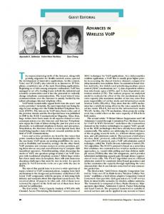
Inter-arrival time of a node in reception
Inter-arrival time of two nodes
140
180
160
120
140
probability distribution
probability distribution
100
120
100
80
80
60
60 40
40 20
20
0
0
0
0.02
0.04
0.06
0.08
0.1
0.12
Fig. 2.
0
0.005
0.01
0.015
0.02
0.025
0.03
0.035
interarrival time (sec)
interarrival time (sec)
Fig. 4.
Distribution of interarrival time for a node
time when a station has the right to initiate transmissions, defined by a starting time and a maximum duration. Therefore, once the node acquires the channel, it can send the packets to different nodes during the TXOP duration. The implementation of the functionality in IEEE 802.11e is similar to the implementation of VMSL. In IEEE 802.11e, the association request and response frames do not need to use any of the reserved bits. When the AP receives a packet destined to one of the users associated with itself, it first checks whether it is a voice packet based on the length of the packet, as described in VMSL. Then it stores the packets in the same way. If this is the first packet to be included in one frame, AP also starts a timer. Then after a certain time or the maximum number of node data that can be included inside the TXOP limit have been received, the AP acquires the channel and send the packets back-to-back during the TXOP duration. IV. I MPLEMENTATION We experimented VoIP in the current IEEE 802.11b system. The VoIP delay analysis consists of delay in a wired domain and in a wireless domain. We focus on the wireless domain since the tuning parameters are limited in the wired domain. In order to get a good estimate for the wireless domain we
Distribution of interarrival time for a node
located the source and destination to the same subnet. They are all attached to the same access point. As a result, in this setting, the inter-arrival delay is the delay budget for the wireless domain. We look at a station and take the difference of receiving times of the ACK. Figure 1 and 2 shows the plot for the instantaneous values; as it can be seen the jitter is around 30ms. This experiment was performed using the department network in Berkeley which also includes other regular traffic. Another test was carried out using Skype VoIP software. This software use Peer-to-Peer methodology. Therefore, in our setting calls are confined within a subnet which means that the wired domain part of the call is very limited and negligible. Figures 3 and 4 show the case when a pair of laptops are connected with Skype software for a voice communication. Now we see that we get jitter less than 30ms but the 30ms is still relevant in the majority of the interarrival times. The calls traverse through the wireless domain to the access point and then from access point to wireless domain. As a result, for each session there are two accesses. For (n) stations, they access the wireless domain (2n − 2) times in this setting since (n − 1) stations perform one session and the access point accesses the channel n−1 times in order to deliver the packets for (n − 1) stations. Packet aggregation removes one wireless
2237 This full text paper was peer reviewed at the direction of IEEE Communications Society subject matter experts for publication in the WCNC 2006 proceedings.
0.7 Optimized w/o Optimization
1.2 Optimized w/o Optimization
0.6
Access Point Throughput (Mbps)
1.1
Throughput (Mbps)
1
0.9
0.8
0.5
0.4
0.3
0.2
0.7 0.1 0.6 0 0.5
0
5
10
15
20
25
30
35
40
45
0
5
10
15
20
25
30
35
40
45
50
Number of Stations
50
Number of Stations
Fig. 6. Fig. 5.
Access point throughput (w/o RTS/CTS)
Total throughput (w/o RTS/CTS) 0.35 Optimized w/o Optimization
domain access per session and reduces the access to (n−1)+1 by aggregation in order to decrease the jitter significantly. Stations Throughput (Mbps)
0.3
V. P ERFORMANCE A NALYSIS We can formulate and analyze the VoIP system as follows. Assume that there are (n − 1) stations and an access point in a network. Each station performs a voice session with a node outside the network. Let’s mark station 1 as the access point. We can infer that in the legacy system packet sizes are equal and are given as follows: P (1) = P (i) f or i ∈ [2, n] E[P ] = P (1)
0.25
0.2
0.15
0.1
0.05
0
0
5
10
15
20
25
30
35
40
45
50
Number of Stations
Fig. 7.
Station throughput (w/o RTS/CTS)
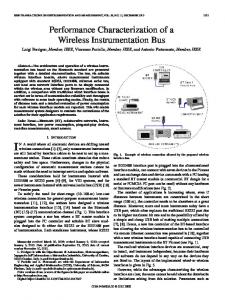
The packet sizes with packet aggregation are: P (1) = min((n − 1)(P (2) + I), 2024) P (2) = P (i) �nf or i ∈ [2, n] E[P ] = n1 i P (i) where I is the number of identifier bytes and 2024 bytes is the maximum allowed payload. We considered 20ms segment at 8kbps which corresponds to 64 bytes MSDU (P (2)) for a single voice session and each station has a packet to transmit all the time with 11 Mbps data rate. In addition, the access point does not expect an ACK packet since it transmits in multicast. Figure 5 shows the total throughput ST of the system found with the formula explained in [10], [11]: ST =
Ps E[P ] (1 − Ptr )σ + T¯s + T¯c
(1)
where E[P ] is the average packet size, T¯s and T¯c are the average duration values for successful transmission and collision respectively, Ps is the probability of successful transmission and Ptr is the probability of transmission in medium. One can see the substantial throughput increase from the figure. As can be inferred, the packet size of the access point increases with the number of stations, which increases the throughput. On the other hand, increase in the number of stations decreases the throughput because of the increased
probability of collision. This comes to a balance for a while and when the maximum allowed packet size is reached, the throughput starts to decrease. Figure 6 shows the access point throughput SA which is found with the following formula: SA =
Ps P (1) 1 n (1 − Ptr )σ + T¯s + T¯c
(2)
Sending the packets in burst increases the throughput of the access point. This throughput calculation considers the successfully transmitted bits but not the received bits. As a result, stations receive packets with higher rates and the station’s transmitted throughput SS is found with the formula below: Ps P (2) 1 (3) SS = n (1 − Ptr )σ + T¯s + T¯c Figure 7 depicts the comparison. As expected, a station’s throughput SS with VoIP algorithm should be lower than that without the algorithm. This is because higher packet size of the access point increases the average duration values. One can easily see that the following equation should hold: ST = SA + (n − 1)SS
2238 This full text paper was peer reviewed at the direction of IEEE Communications Society subject matter experts for publication in the WCNC 2006 proceedings.
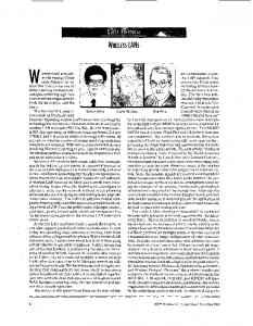
For the frame aggregation, if we look at a scenario when only the access point aggregates the packets into packets of size 2024 bytes (P (1)) we obtain a performance increase that gradually decreases as a new station pops up.Figure 8 shows the total throughput and Figures 9 and 10 show the access point throughput and stations throughput, respectively. In frame aggregation traffic direction could be one destination or multiple destinations. If it is sent with multicast, then there is no need for an ACK packet. Otherwise, for one destination only, one ACK is needed and for multiple destination each station may send an ACK packet one by one with respect to their order in the received packet. This topic is currently being considered in IEEE 802.11n working group.
12 Optimized w/o Optimization
10
Throughput (Mbps)
8
6
4
2
0
0
5
10
15
20
25
30
35
40
45
50
VI. C ONCLUSION
Number of Stations
Fig. 8.
Voice over IP over WLAN is a challenging problem because the IP network is not designed for real-time applications. WLAN protocol should be updated carefully in order to have a voice conversation at an acceptable quality: Real-time aspects of conversation must be respected; the overall delay between both ends of the conversation should be low to avoid irritably long gaps of silence. Based on the fact that the voice packets are very short compared to the data packets and the AP is expected to have more packets that other nodes in the network, we propose a packet aggregation scheme that allows AP to send its packets inside a multicast packet or back-to-back once it acquires the channel. This is shown to increase the throughput considerably.
Total throughput for frame aggregation (w/o RTS/CTS)
6 Optimized w/o Optimization
Access Point Throughput (Mbps)
5
4
3
2
R EFERENCES [1] M. Ergen, S. Coleri, B. Dundar, A. Puri, J. Walrand, P. Varaiya. Position Leverage Smooth Handover Algorithm For Mobile IP. Proceedings of IEEE ICN, August, 2002. [2] J. Liesenborgs. Voice over IP in networked virtual elements. Ph.D dissertation, University of Maastricht, 2000. [3] S. Garp, M. Kappes. Can I add a VoIP call? Proceedings of IEEE ICC 2003, May 2003. [4] D. Awoniyi, F. A. Tobagi. Effect of fading on the performance of VoIP in IEEE 802.11a WLANs. Proceedings of IEEE ICC, June 2004. [5] W. Wang, S. C. Liew, and V. O. K. Li. Solutions to Performance Problems in VoIP over 802.11 Wireless LAN. to appear in IEEE Trans. On Vehicular Technology. [6] P. C. Ng, S. C. Liew, and W. Wang. Voice over WLAN via Wireless Distribution System. Proceedings of IEEE VTC, September 2004. [7] H. Tounsi, L. Toutain, F.Kamaoun. Small packets aggregation in an IP domain. Proceedings of Sixth IEEE Symposium on Computers and Commuincations, July 2001. [8] W. Wang, S. C. Liew, Q. X. Pang, and V. O.K. Li. A Multiplex-Multicast Scheme that Improves System Capacity of Voice-over-IP on Wireless LAN by 100%. Proceedings of The Ninth IEEE Symposium on Computers and Communications, June 2004. [9] W. Wang, S. C. Liew, and J. Y. B. Lee. ABRC: An End-to-End Rate Adaptation Scheme for Multimedia Streaming over Wireless LAN. Proceedings of IEEE WCNC, March 2004. [10] G. Bianchi. Performance Analysis of the IEEE 802.11 Distributed Coordination Function. IEEE Journal on Selected Areas in Communications, vol.18, March 2000. [11] M. Ergen. IWLAN: Intelligent Local Area Networking Ph. D. Thesis, University of California, Berkeley, Fall 2004.
1
0
0
5
10
15
20
25
30
35
40
45
50
Number of Stations
Fig. 9.
Access point throughput for frame aggregation (w/o RTS/CTS)
6 Optimized w/o Optimization
Stations Throughput (Mbps)
5
4
3
2
1
0
0
5
10
15
20
25
30
35
40
45
50
Number of Stations
Fig. 10.
Station throughput for frame aggregation (w/o RTS/CTS)
2239 This full text paper was peer reviewed at the direction of IEEE Communications Society subject matter experts for publication in the WCNC 2006 proceedings.