THz surface plasmon modes on planar Goubau lines D. Gacemi,1 J. Mangeney,1,* T. Laurtent,1 J.-F. Lampin,2 T. Akalin,2 K. Blary,2 A. Degiron,1 P. Crozat,1 and F. Meng1 2
1 Institut d’Electronique Fondamentale, UMR8622 CNRS, Univ. Paris Sud, 91405 Orsay, France Institut d’Electronique de Microélectronique et de Nanotechnologie, UMR8520 CNRS, Univ. Lille I, 59652 Villeneuve d’Ascq, France. *
[email protected]
Abstract: The dispersion relation and confinement of terahertz surface plasmon modes propagating along planar Goubau lines are studied using guided-wave time domain spectroscopy. We demonstrate the radial nature of the surface plasmon mode known as the Goubau mode and the transverse confinement of the electric field over a few tenths of microns (~l/10). We experimentally and computationally observed a transition of the shape of the THz pulses from unipolar to bipolar as the propagation distance increases, indicating that the Goubau line acts as a high-pass filter. The deviation of the dispersion relation curve from a linear law above 600 GHz is discussed. ©2012 Optical Society of America OCIS codes: (240.6680) Surface plasmons; (230.7370) Waveguides; (320.5390) Picosecond phenomena.
References and links 1. 2. 3. 4. 5. 6. 7. 8. 9. 10. 11. 12. 13. 14. 15. 16.
G. Günter, A. A. Anappara, J. Hees, A. Sell, G. Biasiol, L. Sorba, S. De Liberato, C. Ciuti, A. Tredicucci, A. Leitenstorfer, and R. Huber, “Sub-cycle switch-on of ultrastrong light-matter interaction,” Nature 458(7235), 178–181 (2009). Ch. Fattinger and D. Grischkowsky, “Terahertz beams,” Appl. Phys. Lett. 54(6), 490–492 (1989). D. H. Auston, K. P. Cheung, and P. R. Smith, “Picosecond photoconducting Hertzian dipoles,” Appl. Phys. Lett. 45(3), 284–286 (1984). Y. Kawano and K. Ishibashi, “An on-chip near-field terahertz probe and detector,” Nat. Photonics 2(10), 618– 621 (2008). J. Liu, R. Mendis, D. M. Mittleman, and N. Sakoda, “A tapered parallel-plate-waveguide probe for THz nearfield reflection imaging,” Appl. Phys. Lett. 100(3), 031101 (2012). M. Schnell, P. Alonso-González, L. Arzubiaga, F. Casanova, L. E. Hueso, A. Chuvilin, and R. Hillenbrand, “Nanofocusing of mid-infrared energy with tapered transmission lines,” Nat. Photonics 5(5), 283–287 (2011). M. Nagel, P. Haring-Bolivar, M. Brucherseifer, H. Kurz, A. Bosserhoff, and R. Büttner, “Integrated THz technology for label-free genetic diagnostics,” Appl. Phys. Lett. 80(1), 154–156 (2002). J.-Y. Lu, L.-J. Chen, T.-F. Kao, H.-H. Chang, H.-W. Chen, A.-S. Liu, Y.-C. Chen, R.-B. Wu, W.-S. Liu, J.-I. Chyi, and C.-K. Sun, “Terahertz microchip for illicit drug detection,” IEEE Photon. Technol. Lett. 18(21), 2254– 2256 (2006). K. Wang and D. M. Mittleman, “Metal wires for terahertz wave guiding,” Nature 432(7015), 376–379 (2004). H. Zhan, R. Mendis, and D. M. Mittleman, “Superfocusing terahertz waves below λ/250 using plasmonic parallel-plate waveguides,” Opt. Express 18(9), 9643–9650 (2010). S. Laurette, A. Treizebre, F. Affouard, and B. Bocquet, “Subterahertz characterization of ethanol hydration layers by microfluidic system,” Appl. Phys. Lett. 97(11), 111904 (2010). W. C. Chen, J. J. Mock, D. R. Smith, T. Akalin, and W. J. Padilla, “Controlling gigahertz and terahertz surface electromagnetic waves with metamaterial resonators,” Phys. Rev. X 1(2), 021016 (2011). G. Goubau, “Surface waves and their application to transmission lines,” J. Appl. Phys. 21(11), 1119–1128 (1950). T. Akalin, A. Treizebré, and B. Bocquet, “Single-wire transmission lines at terahertz frequencies,” IEEE Trans. Microw. Theory Tech. 54(6), 2762–2767 (2006). M. B. Byrne, J. Cunningham, K. Tych, A. D. Burnett, M. R. Stringer, C. D. Wood, L. Dazhang, M. Lachab, E. H. Linfield, and A. G. Davies, “Terahertz vibrational absorption spectroscopy using microstrip-line waveguides,” Appl. Phys. Lett. 93(18), 182904 (2008). H. M. Heiliger, M. Nagel, H. G. Roskos, H. Kurz, F. Schnieder, W. Heinrich, R. Hey, and K. Ploog, “Lowdispersion thin-film microstrip lines with cyclotene (benzocyclobutene) as dielectric medium,” Appl. Phys. Lett. 70(17), 2233–2235 (1997).
#162136 - $15.00 USD Received 30 Jan 2012; revised 22 Mar 2012; accepted 22 Mar 2012; published 27 Mar 2012
(C) 2012 OSA
9 April 2012 / Vol. 20, No. 8 / OPTICS EXPRESS 8466
17. L. Dazhang, J. Cunningham, M. B. Byrne, S. Khanna, C. D. Wood, A. D. Burnett, S. M. Ershad, E. H. Linfield, and A. G. Davies, “On-chip terahertz Goubau-line waveguides with integrated photoconductive emitters and mode-discriminating detectors,” Appl. Phys. Lett. 95(9), 092903–092905 (2009). 18. A. Treizebre and B. Bocquet, “Nanometric metal wire as a guide for THz investigation of living cells,” Int. J. Nanotechnol. 5(6/7/8), 784–795 (2008). 19. H. Raether, Surface Plasmons on Smooth and Rough Surfaces and on Gratings (Springer-Verlag, Berlin, 1988). 20. J. Mangeney, N. Chimot, L. Meignien, N. Zerounian, P. Crozat, K. Blary, J. F. Lampin, and P. Mounaix, “Emission characteristics of ion-irradiated In0.53Ga0.47As based photoconductive antennas excited at 1.55 microm,” Opt. Express 15(14), 8943–8950 (2007). 21. L. Meignien, J. Mangeney, P. Crozat, L. Duvillaret, and M. Hanna, “Two-port vectorial terahertz electro-optic sampling system,” Appl. Phys. Lett. 92(13), 131103 (2008). 22. C. A. Pfeiffer, E. N. Economou, and K. L. Ngai, “Surface polaritons in a circularly cylindrical interface: Surface plasmons,” Phys. Rev. B 10(8), 3038–3051 (1974). 23. L. Desplanque, E. Peytavit, J. F. Lampin, D. Lippens, and F. Mollot, “Shock wave coupling between terahertz transmission lines on GaAs,” Appl. Phys. Lett. 83(12), 2483–2485 (2003).
1. Introduction Recent advanced research and technological innovation have enabled the emergence of powerful emitters and detectors of free-space terahertz (THz) radiation, with a frequency range of 0.1–10 THz. Today, metrology systems based of free-space radiation are commonly used in fundamental sciences and in many applications [1]. In return, guided-wave THz technology is still an emerging THz field [2,3] motivated by widespread potential applications in near field imaging [4–6], transport THz pulses [7,8] and ultra-wide bandwidth circuits. The current challenge is to guide broadband THz waves with a sub-wavelength transverse confinement, low propagation loss and a weak dispersion. Waveguides that capture and confine THz radiation generated in free-space such as metal wires [9] and parallel-platewaveguides [10] are very promising THz waveguides since they show low attenuation, a weak dispersion and no bandwidth limitation. In addition, two-dimensional confinement of THz energy below l/250 was experimentally demonstrated in parallel-plate-waveguides. Alternative THz waveguides are one-chip waveguides, in which the THz radiation is confined near a surface. On-chip waveguides are defined by lithography techniques and are thus extremely compact. Such waveguides are particularly suited for spectroscopy investigations using microfluidic systems [11], near-field sensing and imaging and ultrafast on-chip signal processing [12]. One very attractive THz on-chip waveguide is the planar Goubau line (G-line), formed by a single rectangular-shaped conducting wire lying on a flat dielectric substrate [13,14]. Indeed, computational investigations of planar Goubau lines have predicted subwavelength transverse electric field confinement around the single conductor [15,16]. Moreover, their designs are extremely simple [17,18]. The electromagnetic Goubau mode is a collective oscillation of electrons on the planar interface between the metallic wire and the dielectric substrate, so-called surface plasmon wave [19]. In this letter, we provide an in-depth experimental analysis of the surface plasmon mode propagating along G-lines using an experiment enabling measurements of the THz electric field directly close to and around the G-line. We experimentally demonstrate 2-D transverse confinement of THz electric field over a few tenths of microns (~l/10) and measure the dispersion relation of the surface plasmon mode. 2. Sample and experimental set-up The investigated G-line is 3-mm-long with a 5-µm width rectangular cross-section signal conductor made from Ti/Au (20/250 nm) and fabricated on a 250 µm-thick quartz substrate. In order to excite the Goubau mode, the G-line is embedded inside a coplanar waveguide with central strip width of 13 µm, ground planes widths of 400 µm, and slots size of 2.2 µm. Tapered sections are inserted at either end of the G-line to provide smooth impedance transformation between the coplanar waveguides and the G-line. This impedance transformation is achieved thanks to a smooth shape of the two ground-planes and a narrowing of the central strip to imitate a planar segment of parabolic horn antenna. The generation of single cycle THz pulses is achieved by the illumination of an ultrafast #162136 - $15.00 USD Received 30 Jan 2012; revised 22 Mar 2012; accepted 22 Mar 2012; published 27 Mar 2012
(C) 2012 OSA
9 April 2012 / Vol. 20, No. 8 / OPTICS EXPRESS 8467
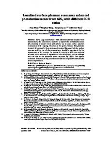
photoconductive switch made by a bonding lifted-off film of 1 µm-thick ion-irradiated In0.53Ga0.47As material [20] deposited onto the coplanar waveguide section. The guided-wave time domain spectroscopy set-up is shown schematically in Fig. 1. The photoconductive switch is dc biased with a voltage of 2.4 V and illuminated by 80 fs optical pulses at ~1550 nm wavelength delivered by an erbium doped fiber laser. The detection of the THz pulses propagating along the G-line is achieved using the nonlinear interaction of optical pulses with the THz pulses in a fiber-coupled electro-optic probe, which consists of a 230-µm-thick ZnTe crystal with a 0.5x0.5 mm2 area sandwiched between two right-angle prisms [21]. The ZnTe crystal can be oriented to detect either the horizontally polarized component or the vertically polarized component of the THz electric field. The spatial resolution of our experiment is limited by the spot size of the optical beam in the ZnTe crystal to 15 µm.
Fig. 1. Optical set-up for characterizing the propagating electromagnetic modes on the planar Goubau line.
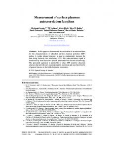
3. Results and discussions The spatial profile of the mode is measured by scanning the electro-optic detector in a plane perpendicular to the G-line axis, with a time delay fixed at the peak of the THz pulse. Figure 2(a) shows the spatial distribution in a (xz) plane of the horizontal (x) and vertical (z) transverse components of the electric field, measured using electro-optic probes with distinct orientations of the ZnTe crystal. The polarity reversal of the horizontal component of the electric field as the electro-optic probe scans across the G-line clearly shows the radial nature of the Goubau mode. These experimental data are consistent with the simulated results of the electric field distribution of the Goubau mode around the center conductor of the G-line previously reported [14,17]. The amplitude of the vertical component of the electric field above the Goubau line versus the z position to the wire is plotted in Fig. 2(b). The amplitude falls to 1/e of its maxima value at 64.5 µm. This value L = 64.5 µm represents the broadband surface plasmon decay length weighted over the broad spectrum of the THz pulse used.
#162136 - $15.00 USD Received 30 Jan 2012; revised 22 Mar 2012; accepted 22 Mar 2012; published 27 Mar 2012
(C) 2012 OSA
9 April 2012 / Vol. 20, No. 8 / OPTICS EXPRESS 8468
120
100
100
z position (µm)
z position ( µm)
(a) 120
80 60 40
60 40 20
20 -120
80
-80
-40
0
40
80
120
0 -120
-80
-40
0
40
80
120
x position (µm)
x position (µm)
Amplitude (a.u.)
(b)
0
20
40
60
80 100 120 140 160 180 200
z position (µm) Fig. 2. (a) Spatial profile of the horizontal (left panel) and vertical (right panel) transverse components of the electric field obtained by using electro-optic probes with distinct orientations of the ZnTe crystal. Red represents positive values and green represents negative values. (b) The amplitude of the vertical component of the electric field above the G-line versus distance to the wire in the z direction. The dashed line indicates the amplitude of the vertical component of the electric field at 1/e of its maxima value.
The propagation characteristics of the radial mode are investigated by moving the electrooptic detector along the G-line axis. Figure 3(a) shows typical time-domain electric field waveforms measured by the electro-optic detector, sensitive to the vertical component of the electric field, located at different positions along the G-line axis (y axis) and just above the center of the wire. As the propagation distance increases, the amplitude of the time-domain waveforms is decreased and the shape is distorted. The full width at half maximum of the pulse is increased by a factor x1.4 after 1.6-mm of propagation resulting in a dispersion coefficient of 0.44 ps/mm. Beyond 1-mm propagation distance, the amplitude is nearly constant (within 10% variation), and a negative peak appears after the main positive peak. The amplitude of this negative peak becomes more intense as the distance increases up to 2 mm. We simulate this effect by computing the electric field of the Goubau mode in the time domain and then projecting it onto vertical axis using the CST’s simulation software. The temporal waveform at the reference is chosen to have a Gaussian profile with a full width at half maximum of 1.4 ps in agreement with the measured waveform at the reference. The simulation of the temporal waveforms at different propagation distances along the G-line confirms the experimentally observed evolution of the shape from unipolar to bipolar as the propagation distance increases (see Fig. 3(b)). This transition in the shape is explained by the fact that the G-line, which is made of a single wire, doesn’t carry the zero frequency component of the electric field. As a consequence, the Fourier transform spectrum is effectively attenuated at low frequency. This dependence of losses with the frequency leads to
#162136 - $15.00 USD Received 30 Jan 2012; revised 22 Mar 2012; accepted 22 Mar 2012; published 27 Mar 2012
(C) 2012 OSA
9 April 2012 / Vol. 20, No. 8 / OPTICS EXPRESS 8469
Ref
Amplitude (arbitrary units)
Amplitude (arbitrary units)
Gibbs phenomenon in the time domain (which is stronger if the frequency dependence of losses is stronger), giving rise to the negative part of the temporal waveform as the propagation distance increases.
(a)
400µm 800µm
1.6 mm 2 mm 1.2 mm
4
6
8
10 12 14 16 18 20 22 24
Ref
800µm 1.2 mm 1.6 mm 2 mm
4
Time (ps)
(b)
400µm
6
8
10 12 14 16 18 20 22 24
Time (ps)
Fig. 3. (a) THz waveforms measured by the electro-optic detector sensitive to the vertical component of the electric field and located at different positions along the G-line axis (y axis) (b) Simulation of the temporal waveforms at different propagation distances along the G-line.
Detailed information concerning the propagation of the surface plasmon mode as a function of frequency are extracted from the Fourier transforms of the measured time-domain waveforms. The real part of the surface plasmon wave number k is directly obtained from the phase difference of the complex Fourier transform between the pulse at the reference of the G-line and the pulse after propagating along the G-line axis. Figure 4(a) shows the dispersion relation of the surface plasmon waves which travel on the G-line together with the plane wave dispersion relation in air. The dispersion curve follows a linear law up to ~600 GHz. Above 600 GHz, a deviation from the linear law is observed, indicating a decrease of the real part of the refraction index of the Goubau mode. The simulation indicates that below 600 GHz, all the energy of the Goubau is located around the conductor line while above this frequency the spatial distribution of the Goubau mode is slightly modified and a part of the energy is located in the substrate. As a consequence, the real part of the refractive index of the Goubau mode increases to come close to the real part of the refractive index of the substrate. From the calculation of the dispersion of the non-radiative plasmon modes in cylindrical geometry [22] and by approximating that the surface plasmon mode is a transverse electromagnetic mode, the surface plasmon electric field decay length in the radial direction (perpendicular to the propagation direction) can be expressed as Eq. (1):
δL =
1 2 y
k − k02
(1)
where k0 is the free-photon wavector and ky is the wavevector in the y direction (along the Gline axis). Given a frequency of 0.5 THz, an electric field decay length dL of 54-mm is deduced. Such decay length corresponds to a confinement of the Goubau mode of approximately λ/10. The electric field decay length dL predicted by this very simple model is lower than the value L of the decay length deduced from the two-dimensional electric field distribution measurements because the real G-line has rectangular shape. In addition, dL is given at a specific frequency in contrast to the value L which is weighted over the THz frequency spectrum including the less confined low frequency components. The electric field amplitude attenuation coefficient as a function of frequency is plotted on Fig. 4(b). Below 200 GHz, the attenuation decreases with the increase of the frequency due to the suppression of the low frequencies observed in Fig. 3. At frequency higher than 200 GHz, the losses are dominated by the metal skin-effect losses, the dielectric losses in the substrate
#162136 - $15.00 USD Received 30 Jan 2012; revised 22 Mar 2012; accepted 22 Mar 2012; published 27 Mar 2012
(C) 2012 OSA
9 April 2012 / Vol. 20, No. 8 / OPTICS EXPRESS 8470
and the radiative losses. The radiative losses located at frequencies around 0.48 THz and 0.68 THz correspond to the excitation of substrate modes of the G-line [23]. At 0.63 THz, the losses are 0.7 mm−1 corresponding to 6 dB/mm, a value comparable to the typical losses measured in conventional coplanar waveguides in the THz range. 1.0
2.0
(b) -1
0.8
Attenautation mm
Frequency (THz)
(a)
0.6 0.4 0.2 0.0
0
10
20
-1
ky(mm )
30
40
1.5
1.0
0.5
0.0 0.0
0.1
0.2
0.3
0.4
0.5
0.6
0.7
Frequency (THz)
Fig. 4. (a) The dispersion relation of the surface plasmon waves which travel on the G-line, derived from a series of measurements with different propagation distances. The plane wave dispersion relation in air is indicated by the dashed line. The error bars show +−1 s.d. (b) The electric field amplitude attenuation coefficient of the propagating plasmon mode as a function of frequency, derived from the spectrum of the measured waveforms at the reference and after 2 mm of propagation distance.
7. Conclusion In conclusion, planar Goubau lines, which combine the simplicity of a single conductor with a subwavelength confinement of electric field (~l/10) are very promising plasmonic waveguides for broadband THz near-field sensing and imaging, spectroscopy of microfluidic systems and ultra-wide bandwidth circuits.
#162136 - $15.00 USD Received 30 Jan 2012; revised 22 Mar 2012; accepted 22 Mar 2012; published 27 Mar 2012
(C) 2012 OSA
9 April 2012 / Vol. 20, No. 8 / OPTICS EXPRESS 8471