Journal of
Marine Science and Engineering Article
Tidal Datum Changes Induced by Morphological Changes of North Carolina Coastal Inlets Jindong Wang 1,2, * and Edward Myers 1 1 2
*
Coast Survey Development Laboratory, National Ocean Service, National Oceanic and Atmospheric Administration, 1315 East-West Highway, Silver Spring, MD 20910, USA;
[email protected] Earth Resources Technology, Inc., 14401 Sweitzer Lane, Suite 300, Laurel, MD 20707, USA Correspondence:
[email protected]; Tel.: +1-301-713-2809
Academic Editor: Richard P. Signell Received: 18 July 2016; Accepted: 12 November 2016; Published: 18 November 2016
Abstract: In support of the National Oceanic and Atmospheric Administration’s VDatum program, a new version of a tidal datum product for the North Carolina coastal waters has been developed to replace the initial version released in 2004. Compared with the initial version, the new version used a higher resolution grid to cover more areas and incorporated up-to-date tide, bathymetry, and shoreline data. Particularly, the old bathymetry datasets that were collected from the 1930s to the 1970s and were used in the initial version have been replaced by the new bathymetry datasets collected in the 2010s in the new version around five North Carolina inlets. This study aims at evaluating and quantifying tidal datum changes induced by morphological changes over about 40 to 80 years around the inlets. A series of tidal simulations with either the old or new bathymetry datasets used around five inlets were conducted to quantify the consequent tidal datum changes. The results showed that around certain inlets, approximately 10% change in the averaged depth could result in over 30% change in the tidal datum magnitude. Further investigation also revealed that tidal datum changes behind the barrier islands are closely associated with the cross-inlet tidal flux changes. Keywords: VDatum; tidal datums; morphological changes; inlets; North Carolina
1. Introduction The software package VDatum, developed and maintained by the National Oceanic and Atmospheric Administration (NOAA), allows users to transform geospatial data among a variety of ellipsoidal, orthometric, and tidal datums [1]. For example, users can integrate the United States Geological Survey’s elevation data referenced to the North American Vertical Datum of 1988 (NAVD88) with NOAA’s sounding data referenced to Mean Lower Low Water (MLLW) to build a seamless bathymetry-topography Digital Elevation Model (DEM) dataset referenced to a common datum of Mean Sea Level (MSL) by using VDatum. The integrated DEM provides a basis for coastal inundation modeling and mapping [2]. As a critical part of VDatum, tidal datums are derived from water level time series simulated by a tide model. The tidal highs and lows from modeled water levels are used to calculate tidal datums: Mean Higher High Water (MHHW), Mean High Water (MHW), Mean Low Water (MLW), and Mean Lower Low Water (MLLW) [3]. Following the VDatum Standard Operating Procedures [4], we use the ADvanced CIRCulation (ADCIRC) model [5] to conduct tidal simulations for deriving tidal datums in VDatum. The ADCIRC model has been widely used for tidal simulations from the basin scale [6–8] to the regional scale [9–11]. The initial version of VDatum for North Carolina was released in 2004 [12]. An updated version has been developed to cover more areas and incorporate up-to-date tide, bathymetry, and shoreline J. Mar. Sci. Eng. 2016, 4, 79; doi:10.3390/jmse4040079
www.mdpi.com/journal/jmse
J. Mar. Sci. Eng. 2016, 4, 79
2 of 17
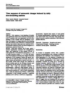
data. Around five main North Carolina inlets (Beaufort, Barden, Ocracoke, Hatteras, and Oregon Inlet), the bathymetry datasets collected from the 1930s to the 1970s were used in the initial version for tide modeling to derive tidal datums. These old bathymetry datasets have been replaced by the datasets collected in the 2010s around five inlets in the updated version. Tidal datum changes induced by morphological changes of the inlets need to be quantified to provide NOAA guidance for future updating of VDatum, installing new tide gauges, and conducting new hydrographic surveys in this region. Tidal inlets are typically dynamically active regions where tidal circulation and transport lead to continuous sediment movement and thus morphological changes. In general, the combination of tides and waves was considered to shape the inlet morphology into different types: flood-tidal delta and ebb-tidal delta [13–16]. Tidal distortion was found to affect net sediment transport [17,18]. Tidal prism and inlet cross-sectional area were also considered as important factors to affect the inlet morphology [19]. Around North Carolina’s Beaufort Inlet, a nearshore jet in tidal circulation was identified and simulated and was considered to be associated with the net transport through the inlet [20,21]. Sediment deposition and erosion around North Carolina inlets was investigated with the local dynamics by Inman and Dolan [22]. These previous studies have mainly been focused on how hydrodynamics (e.g., tides and waves) affect the morphology of the inlets. Little attention has been paid to the feedback of tides to morphological changes of the inlets. In this study, we aimed at evaluating and quantifying how morphological changes of the inlets affect tidal changes. This paper is organized as follows: following the introduction section, Section 2 describes the sources of a variety of tide, shoreline, and bathymetry data, as well as the tide model setup, numerical experiment design, and model validation. The results will be described in Section 3 followed by some discussions and conclusions in the last section. 2. Materials and Methods 2.1. Data Sources The water level data [23] and the observed tidal datums [24] provided by the Center for Operational Oceanographic Products and Services (CO-OPS) of NOAA were used for model validation. CO-OPS typically publishes one single value for a particular tidal datum (e.g., MHW) at one station. The tidal datums were typically derived from the water level time series for a certain time period (from a couple of months to years). The observed tidal datums were referenced to the current National Tidal Datum Epoch (NTDE) (1983–2001) [24]. In this paper, the observed tidal datums at 31 tide stations were compared with the modeled tidal datums to evaluate the general model performance in North Carolina coastal waters. Since the identification (ID) numbers of all North Carolina stations begin with 865, the 865 will be ignored when we describe station IDs in the following discussions. The locations of all 31 datum stations are shown in Figure 1. Among these stations, the 4 outside stations 1370, 4400, 6590, and 6937 are located on the Atlantic Ocean coast. The other 27 inside stations are located behind the barrier islands and within the sounds and estuaries. Among the 31 datum stations, tidal harmonic constituents are also provided for 16 stations [25]. In addition, the hourly water level data collected from 1967 to 2016 at Beaufort Station (ID: 6483), about 4 km behind the Beaufort Inlet and Duck Station (ID: 1370) on the Atlantic coast, were used to evaluate the temporal variation of MHW. The development of the hydrodynamic model grid requires shoreline and bathymetry data. The National Geodetic Survey provided the up-to-date North Carolina shoreline data which combined NOAA Continually Updated Shoreline Product (CUSP) and the Office of Coast Survey (OCS) chart shoreline data [26]. The bathymetry data were mainly from three sources. The OCS sounding data collected from 1851 to 2012 were used for most of the North Carolina coastal regions. The particular areas covered by the datasets collected in a certain year can be found in a Bathymetry Data Viewer [27]. A global bathymetry-topography database SRTM30_PLUS from Scripps Institution of Oceanography
J. Mar. Sci. Eng. 2016, 4, 79
3 of 17
J. Mar. Sci. Eng. 2016, 4, 79
3 of 17
was used for the far offshore region [28]. The sounding data collected since 2010 by the U.S. Army Engineers’ District were used for coastal inletsfor and intra-coastal waterways [29].4 of 17 J. Mar.Corps Sci. U.S. Eng. 2016, 4, Corps 79 Wilmington the Army Engineers’ Wilmington District were used coastal inlets and intra-coastal All the up-to-date tide, and shoreline dataand have been applied to derive updated tidal waterways [29]. All thebathymetry, up-to-date tide, bathymetry, shoreline data have been the applied to derive datums used by the currently available VDatum tool. have the theupdated same depths interpolated from the same bathymetry datasets described in Section 2.1. tidal datums used by the currently available VDatum tool.
Therefore, the only difference between the old-bathy grid and the new-bathy grid was the bathymetry around the five inlets. The same model setup and tidal forcing were applied to the models using the old-bathy grid and the new-bathy grid. In the following discussions, we will use the old-bathy model and the new-bathy model to represent the models using the old-bathy grid and the new-bathy grid, respectively. Since Beaufort Inlet and Barden Inlet are close to each other, we made another two grids new-bathy-BE and new-bathy-BA to evaluate the tidal datum changes induced by the morphological changes of each individual inlet. For the new-bathy-BE grid, the new bathymetry data were used around Beaufort Inlet and the old bathymetry data were used for the other four inlets. Similarly, for the new-bathy-BA grid, the new bathymetry data were used around Barden Inlet and the old bathymetry(a) data were used for the other four inlets.(b) We will use the new-bathy-BE model and the new-bathy-BA model to represent tidal simulations using the new-bathy-BE grid and Figure 1. Map of North Carolina coastal waters and inlets and the locations of the National Oceanic Figure 1. Map of North Carolina coastal waters and inlets and the locations of the National Oceanic and the new-bathy-BA grid, respectively, the following and Atmospheric Administration in (NOAA) water leveldiscussions. stations (black dots): (a) Northern part; (b) Atmospheric Administration (NOAA) water level stations (black dots): (a) Northern part; (b) Southern The overview of Please the common area bathymetry is shown in(a). Figure 2b. Most regions behind the Southern part. note that the scale in (b) is 4 times larger than part. Please note that the scale in (b) is 4 times larger than (a). barrier islands are shallower than 8 m. There are significant bathymetric differences between the 2.2. Model Setup old-bathy gridSetup and the new-bathy grid around the inlets, as shown in Figures 3–5. For example, 2.2. Model around Beaufort Inlet [5] (Figure 3), the meanDepth depthIntegrated has increased 44% was fromused the in old-bathy of The ADCIRC Two-Dimensional (2DDI)by version this studydepth to The ADCIRC [5] Two-Dimensional Depth Integrated (2DDI) version was used in this study to solve thenew-bathy shallow water equations andInsimulate tidal water levels. The finite became amplitude and and 5.0 msolve to the depth of 7.2 m. addition, the recent deep channel deeper the shallow water equations and simulate tidal water levels. The finite amplitude and convection convection terms and60 the wetting and drying option were activated. The lateral Beaufort viscosity was setshould as a widerterms relative years ago. These morphological changes around and to theabout wetting and drying option were activated. The lateral viscosity was set as Inlet a constant, be −2 constant, 5.0 m· s , throughout the model domain. The quadratic bottom friction scheme was used 22%, mainly with historical dredging [30]. The mean depths increased bywith 70%, 5.0associated m·s−2 , throughout the model domain. activities The quadratic bottom friction scheme was used a with a constant coefficient of 0.0025. The model was forced by a reconstructed tide at the ocean 4%, and 11% coefficient from the of old-bathy grid to the grid around tide Barden constant 0.0025. The model wasnew-bathy forced by a reconstructed at theInlet, oceanOcracoke boundary Inlet, boundary (shown as blue lines in Figure 2a) using the harmonic constants of the five most significant (shown as and blueOregon lines in Figure 2a) using the The harmonic constants of the five most Hatteras Inlet, Inlet, respectively. morphological parameters forsignificant five inletstidal are listed tidal constituents (M2, S2, N2, K1, and O1) from the EC2001 tidal database [7]. constituents 2 , S2 , N2 , K1 , and O1 ) from the EC2001 tidal database [7]. in Table 1.The time(Mstep was set to be 1 s. Under this condition, the maximum Courant number is 0.67 over the smallest elements in the grid. This ensured model stability. The model simulations covered a time period of 40 days. The first 10 days were used for the tidal field to reach an equilibrium state. The 6-min water level time series at each node from the last 30 days of each simulation were then used to derive tidal datums and harmonic constants. The 15-min velocity time series at each node from the last 15 days of each simulation were used to calculate the flood and ebb fluxes across the inlets. A triangular mesh (Figure 2a) has been developed with a spatially varying resolution from 30 km offshore to 10 m inland to resolve important geographical features such as inlets, channels, estuaries, and bays. We used this mesh as a basis to generate the model grids by interpolating the old (1930s–1970s) and the new (2010s) bathymetry datasets around five North Carolina inlets (Beaufort, Barden, Ocracoke, Hatteras, and Oregon Inlet) onto the mesh. In the following discussions, we will use the old-bathy grid to represent the model grid using the old (1930s–1970s) bathymetry data and use the new-bathy grid to represent the model grid using the new (2010s) bathymetry data around the inlets. The particular collection years for the old and new bathymetry (a) (b)datasets around each inlet have been listed in Table 1. For the old-bathy grid, we combined the patched bathymetry datasets Figure 2. (a) The triangular model grid lines delineate the open ocean boundary; theregion green Figure (a) The model grid(the (the blue blue delineate the open ocean boundary; the green collected in2.1956 andtriangular 1962 around Ocracoke Inletlines to represent the general morphology in this lines delineate the land boundary); (b)(b) Model grid bathymetry Carolina coastalcollected waters (the delineate the land Model grid bathymetry inNorth North Carolina coastal waters in thelines mid-20th century. Forboundary); the new-bathy grid, we combined in the bathymetry datasets in regions deeper than 20 m use the same blue color; the black line shows the location for longitudinal (the regions deeper than 20 m use the same blue color; the black line shows the location for longitudinal 2014, 2015, and 2016 around Hatteras Inlet and the bathymetry datasets collected in 2014 and 2016 profiles in Figures 15to and 16). profiles inOregon Figures 15 and 16). around Inlet represent the recent morphology in these two regions. The detailed coverages of the old and the new bathymetry datasets are shown for Beaufort and Barden Inlet in Table Bathymetric and Inlet morphological parameters around North Carolina Figure 3d,1.Ocracoke and data Hatteras in Figure 4d, and Oregon Inletfive in Figure 5d. Otherinlets. than the inlet regions delineated by the polygons in Figures 3–5, the old-bathy grid and the new-bathy grid Area with Mean Mean Collection Collection Width Changed Depth of Depth of Inlet Years of Old Years of New (km) Bathymetry Old-Bathy New-Bathy
J. Mar. Sci. Eng. 2016, 4, 79
4 of 17
The time step was set to be 1 s. Under this condition, the maximum Courant number is 0.67 over the smallest elements in the grid. This ensured model stability. The model simulations covered a time period of 40 days. The first 10 days were used for the tidal field to reach an equilibrium state. The 6-min water level time series at each node from the last 30 days of each simulation were then used to derive tidal datums and harmonic constants. The 15-min velocity time series at each node from the last 15 days of each simulation were used to calculate the flood and ebb fluxes across the inlets. A triangular mesh (Figure 2a) has been developed with a spatially varying resolution from 30 km offshore to 10 m inland to resolve important geographical features such as inlets, channels, estuaries, and bays. We used this mesh as a basis to generate the model grids by interpolating the old (1930s–1970s) and the new (2010s) bathymetry datasets around five North Carolina inlets (Beaufort, Barden, Ocracoke, Hatteras, and Oregon Inlet) onto the mesh. In the following discussions, we will use the old-bathy grid to represent the model grid using the old (1930s–1970s) bathymetry data and use the new-bathy grid to represent the model grid using the new (2010s) bathymetry data around the inlets. The particular collection years for the old and new bathymetry datasets around each inlet have been listed in Table 1. For the old-bathy grid, we combined the patched bathymetry datasets collected in 1956 and 1962 around Ocracoke Inlet to represent the general morphology in this region in the mid-20th century. For the new-bathy grid, we combined the bathymetry datasets collected in 2014, 2015, and 2016 around Hatteras Inlet and the bathymetry datasets collected in 2014 and 2016 around Oregon Inlet to represent the recent morphology in these two regions. The detailed coverages of the old and the new bathymetry datasets are shown for Beaufort and Barden Inlet in Figure 3d, Ocracoke and Hatteras Inlet in Figure 4d, and Oregon Inlet in Figure 5d. Other than the inlet regions delineated by the polygons in Figures 3–5, the old-bathy grid and the new-bathy grid have the same depths interpolated from the same bathymetry datasets described in Section 2.1. Therefore, the only difference between the old-bathy grid and the new-bathy grid was the bathymetry around the five inlets. Table 1. Bathymetric data and morphological parameters around five North Carolina inlets. Inlet
Width (km)
Area with Changed Bathymetry (km2 )
Beaufort 1.3 Barden 0.7 Ocracoke 2.4 Hatteras 2.2 Oregon 1.0 J. Mar. Sci. Eng. 2016, 4, 79
6.2 4.3 8.8 8.7 3.7
Collection Years of Old Bathymetry
Mean Depth of Old-Bathy (m)
Collection Years of New Bathymetry
1953 1955 1956, 1962 1935 1975
5.0 1.7 4.0 2.6 3.6
2010 2015 2013 2014, 2015, 2016 2014, 2016
(a)
(b)
Figure 3. Cont.
Mean Depth of New-Bathy (m) 7.2 2.9 4.9 2.7 4.0 5 of 17
J. Mar. Sci. Eng. 2016, 4, 79
5 of 17
(a) (a)
(b)
(c) (c)
(d) (d)
Figure 3. The morphological changes around Beaufort Inlet and Barden Inlet: (a) the old-bathy grid
The morphological changesaround aroundBeaufort Beaufort Inlet Inlet: (a) the grid grid FigureFigure 3. The3.morphological changes Inletand andBarden Barden Inlet: (a) old-bathy the old-bathy depths; (b) the new-bathy grid depths; (c) the depth difference between the new-bathy grid and the depths; (b)new-bathy the new-bathy grid depths;(c) (c)the thedepth depth difference between thethe new-bathy grid and the depths; (b) the grid depths; difference between new-bathy grid and the old-bathy grid; (d) the original bathymetry sounding data points (orange: data in 1953 around old-bathy grid; (d) the original bathymetry sounding data points (orange: data in 1953 around old-bathy grid; (d) the original data points data inBeaufort 1953 around Beaufort Beaufort Inlet and data inbathymetry 1955 around sounding Barden Inlet; blue: data (orange: in 2010 around Inlet and Beaufort Inlet and data in 1955 around Barden Inlet; blue: data in 2010 around Beaufort Inlet and Inlet and data 1955 around Barden Inlet; inpolygons 2010 around Beaufort Inlet andchanged data in 2015 data in in 2015 around Barden Inlet). The blue: black data dotted delineate the area with data in 2015 around Barden Inlet). The black dotted polygons delineate the area with changed around bathymetry. Barden Inlet). The black dotted polygons delineate the area with changed bathymetry. bathymetry.
J. Mar. Sci. Eng. 2016, 4, 79
(a) (a)
(b) (b)
(c)
(d)
6 of 17
Figure 4. The morphological changes around Ocracoke Inlet and Hatteras Inlet: (a) the old-bathy grid
Figure 4. The morphological changes around Ocracoke Inlet and Hatteras Inlet: (a) the old-bathy grid depths; (b) the new-bathy grid depths; (c) the depth difference between the new-bathy grid and the depths;old-bathy (b) the new-bathy depths; (c) the depth difference between the new-bathy grid and the grid; (d) thegrid original bathymetry sounding data points (orange: data in 1956 and 1962 old-bathy grid;Ocracoke (d) the original data points (orange: in 1956 and 1962 around around Inlet andbathymetry data in 1935sounding around Hatteras Inlet; blue: data data in 2013 around Ocracoke Ocracoke and in data in2015, 1935and around Hatteras Inlet;Inlet). blue:The data in 2013 around Ocracoke InletInlet and data 2014, 2016 around Hatteras black dotted polygons delineateInlet the and with changed bathymetry. data inarea 2014, 2015, and 2016 around Hatteras Inlet). The black dotted polygons delineate the area with changed bathymetry.
(c)
(d)
Figure 4. The morphological changes around Ocracoke Inlet and Hatteras Inlet: (a) the old-bathy grid depths; (b) the new-bathy grid depths; (c) the depth difference between the new-bathy grid and the old-bathy grid; (d) the original bathymetry sounding data points (orange: data in 1956 and 1962 around Ocracoke Inlet and data in 1935 around Hatteras Inlet; blue: data in 2013 around Ocracoke J. Mar. Sci. Eng. 2016, 4, 79 Inlet and data in 2014, 2015, and 2016 around Hatteras Inlet). The black dotted polygons delineate the area with changed bathymetry.
(a)
(b)
(c)
(d)
6 of 17
Figure 5. The morphological changes around Oregon Inlet: (a) the old-bathy grid depths; (b) the
Figure new-bathy 5. The morphological around Oregon (a) the grid old-bathy depths; grid depths; (c) changes the depth difference between Inlet: the new-bathy and the grid old-bathy grid; (b) the new-bathy grid depths; (c) the depth difference between new-bathy grid Oregon and theInlet; old-bathy (d) the original bathymetry sounding data points (orange:the data in 1975 around blue: grid; (d) the data original bathymetry sounding dataInlet). points datapolygons in 1975 delineate around Oregon Inlet; blue: in 2014 and 2016 around Oregon The(orange: black dotted the area with bathymetry. data inchanged 2014 and 2016 around Oregon Inlet). The black dotted polygons delineate the area with changed bathymetry.
The same model setup and tidal forcing were applied to the models using the old-bathy grid and the new-bathy grid. In the following discussions, we will use the old-bathy model and the new-bathy model to represent the models using the old-bathy grid and the new-bathy grid, respectively. Since Beaufort Inlet and Barden Inlet are close to each other, we made another two grids new-bathy-BE and new-bathy-BA to evaluate the tidal datum changes induced by the morphological changes of each individual inlet. For the new-bathy-BE grid, the new bathymetry data were used around Beaufort Inlet and the old bathymetry data were used for the other four inlets. Similarly, for the new-bathy-BA grid, the new bathymetry data were used around Barden Inlet and the old bathymetry data were used for the other four inlets. We will use the new-bathy-BE model and the new-bathy-BA model to represent tidal simulations using the new-bathy-BE grid and the new-bathy-BA grid, respectively, in the following discussions. The overview of the common area bathymetry is shown in Figure 2b. Most regions behind the barrier islands are shallower than 8 m. There are significant bathymetric differences between the old-bathy grid and the new-bathy grid around the inlets, as shown in Figures 3–5. For example, around Beaufort Inlet (Figure 3), the mean depth has increased by 44% from the old-bathy depth of 5.0 m to the new-bathy depth of 7.2 m. In addition, the recent deep channel became deeper and wider relative to about 60 years ago. These morphological changes around Beaufort Inlet should be mainly associated with historical dredging activities [30]. The mean depths increased by 70%, 22%, 4%, and 11% from the old-bathy grid to the new-bathy grid around Barden Inlet, Ocracoke Inlet, Hatteras Inlet, and Oregon Inlet, respectively. The morphological parameters for five inlets are listed in Table 1.
J. Mar. Sci. Eng. 2016, 4, 79 J. Mar. Sci. Eng. 2016, 4, 79
7 of 17 7 of 17
2.3. Model Validation Computed tidal datums from both the old-bathy model and the new-bathy model were 2.3. Model Validation compared with the observed tidal datums at 31 stations. The root mean squared errors (RMSEs) of Computed tidal datums from both thebeen old-bathy model thegeneral, new-bathy were both models for four tidal datums have listed in Tableand 2. In bothmodel models hadcompared decent with the observed tidal datums at 31 stations. The root mean squared errors (RMSEs) of bothoverall models performances relative to the observations. The new-bathy model had a little higher forperformance four tidal datums been listed inItTable 2. In both decent performances than thehave old-bathy model. should be general, noted that themodels RMSEs had of the new-bathy model relative to thehigher observations. The new-bathy model had aonlittle higher overall performance than the are slightly than the uncertainty values published the VDatum website [31]. This is mainly old-bathy model. It should betidal noted that the RMSEs of thefrom new-bathy model are of slightly higher than because the official VDatum datums were calculated longer time series simulated water levels. the uncertainty values published on the VDatum website [31]. This is mainly because the official VDatum tidal datums were calculated from longer time series of simulated water levels. Table 2. The root mean squared errors of the modeled tidal datums relative to the observed ones.
Table 2. The root mean squared errors of the modeled tidal datums relative to the observed ones.
Mean Higher Mean High Mean Low High Water Mean Higher High Water Water Mean(MHW) High Water Water Mean(MLW) Low Water Model Model (MHHW) (MHHW) (cm) (MHW) (cm) (MLW) (cm) (cm) (cm) (cm) Old-bathy Model 6.1 4.6 4.5 Old-bathy 6.1 4.6 3.5 4.53.3 New-bathy ModelModel 4.8 New-bathy Model 4.8 3.5 3.3
Mean Lower MeanWater Lower Low Low Water (MLLW) (MLLW) (cm) (cm) 6.0
6.0 4.5 4.5
Since the four tidal datums have similar trend and patterns, only MHW will be discussed as an Since the four tidal datums have similar trend and patterns, only MHW will be discussed as an example in the rest of the paper. The result for MHW is shown in Figure 6. The new-bathy model example in the rest of the paper. The result for MHW is shown in Figure 6. The new-bathy model outperformed the old-bathy model at particular stations. At the inside stations not too far away from outperformed the old-bathy model at particular stations. At the inside stations not too far away from the inlets (e.g., 2678, 6084, and 6483), the new-bathy model matched the observations very well while the inlets (e.g., 2678, 6084, and 6483), the new-bathy model matched the observations very well while the old-bathy model underestimated the observations by approximately 5% to 25%. This is because the old-bathy model underestimated the observations by approximately 5% to 25%. This is because tidal datums dramaticallythan thanother otherstations stationsand andthe the new-bathy tidal datumsatatthese thesestations stationshad hadchanged changed more more dramatically new-bathy model simulation Tidal Datum Datum Epoch Epoch(1983–2001) (1983–2001)conditions. conditions.AtAt model simulationisiscloser closerto tothe thecurrent current National National Tidal thethe outside stations and the inside stations far away from the inlets (e.g., 1370, 3365, and 6590), the MHW outside stations and the inside stations far away from the inlets (e.g., 1370, 3365, and 6590), the values both models very small MHWfrom values from both had models had verydifferences. small differences. 0.8
Observed Old-bathy model Errors of old-bathy model New-bathy model Errors of new-bathy model
MHW (m)
0.6 0.4 0.2
6937
6841
6612
6590
6539
6518
6502
6483
6467
6306
6201
6084
5875
5151
4792
2678
4572
2648
4467
2587
4400
2547
3951
2437
3365
2247
3215
2232
2905
1817
-0.2
1370
0
1
2
3
4
5
6
7
8
9 10 11 12 13 14 15 16 17 18 19 20 21 22 23 24 25 26 27 28 29 30 31 Station
Figure between the theobservations observations(black (blackdots), dots),thethe Figure6. 6.Comparison Comparison of of MHW MHW at at 31 31 NOAA NOAA stations stations between old-bathy model (blue (bluesolid solidsquares). squares).The Theblank blank old-bathymodel model(red (redsolid soliddiamonds), diamonds), and and the the new-bathy new-bathy model diamondsand andsquares squaresindicate indicatethe themodel model errors. errors. diamonds
The amplitudes and phases of five principal tidal constituents (M2, S2, N2, K1, and O1) from both The amplitudes and phases of five principal tidal constituents (M2 , S2 , N2 , K1 , and O1 ) from both models were also compared with the observations at 16 stations. As an example, the results for M2 models were also compared with the observations at 16 stations. As an example, the results for M2 (Figures 7 and 8) indicate that the old-bathy model and the new-bathy model had decent (Figures 7 and 8) indicate that the old-bathy model and the new-bathy model had decent performance. performance. For some stations with small amplitude (e.g., 5875), the discrepancy between the For some stations with small amplitude (e.g., 5875), the discrepancy between the modeled phase and modeled phase and the observed phase could be relatively high because the obscured tidal signals in the observed phase could be relatively high because the obscured tidal signals in the observed water the observed water level time series led to high uncertainty in the observed phase itself. level time series led to high uncertainty in the observed phase itself.
J. Mar. Sci. Eng. 2016, 4, 79 J. Mar. Sci. Eng. 2016, 4, 79
8 of 17 8 of 17
At the inside stations not too far away from the inlets (e.g., 2678 and 6483), the new-bathy not too far away from the inlets (e.g., 2678 and 6483), the new-bathy 8 of 17 model outperformed the old-bathy model. The old-bathy model had underestimated amplitudes model outperformed the old-bathy model. The old-bathy model had underestimated amplitudes and overestimated phases relative to the observations. and overestimated phases relative to the observations.
AtEng. the2016, inside J. Mar. Sci. 4, 79stations
Observed Observed Old-bathy model Old-bathy model Errors of old-bathy model Errors of old-bathy model New-bathy model New-bathy model Errors of new-bathy model Errors of new-bathy model
amplitude(m) (m) MM amplitude 2 2
0.6 0.6 0.4 0.4 0.2 0.2 0 0
1370 1370
2247 2247
2437 2437
2547 2547
2587 2587
2678 2678
3951 3951
4400 4400
4467 4467
4792 4792
5875 5875
6201 6201
6467 6467
6483 6483
6590 6590
6841 6841
-0.2 -0.2
1 1
2 2
3 3
4 4
5 5
6 6
7 7
8 9 8 9 Station Station
10 10
11 11
12 12
13 13
14 14
15 15
16 16
Figure 7. Comparison of the M2 amplitude at 16 NOAA stations between the observations (black Figure Comparison 2 amplitude at NOAA 16 NOAA stations between the observations (black Figure 7. 7. Comparison of of thethe M2M amplitude at 16 stations between the observations (black dots), dots), the old-bathy model (red solid diamonds), and the new-bathy model (blue solid squares). The the old-bathy model (reddiamonds), solid diamonds), and the new-bathy squares). The thedots), old-bathy model (red solid and the new-bathy modelmodel (blue (blue solid solid squares). The blank blank diamonds and squares indicate the model errors. blank diamonds and squares the model diamonds and squares indicateindicate the model errors.errors. 120 120
Observed Observed Old-bathy model Old-bathy model Errors of old-bathy model Errors of old-bathy model New-bathy model New-bathy model Errors of new-bathy model Errors of new-bathy model
60 60 30 30 0 0
2437 2437
2547 2547
2587 2587
2678 2678
3951 3951
4400 4400
4467 4467
4792 4792
5875 5875
6201 6201
6467 6467
6483 6483
6590 6590
6841 6841
-60 -60
2247 2247
-30 -30
1370 1370
phase(deg) (deg) MM phase 2 2
90 90
1 1
2 2
3 3
4 4
5 5
6 6
7 7
8 9 8 9 Station Station
10 10
11 11
12 12
13 13
14 14
15 15
16 16
Figure8.8.Comparison Comparison of theM M2 phase at at 16 NOAA stations (black dots), Figure stationsbetween betweenthe theobservations observations (black dots), Figure 8. Comparisonofofthe the M22 phase phase at 16 16 NOAA NOAA stations between the observations (black dots), the old-bathy model (red solid diamonds), and the new-bathy model (blue solid squares). The blank thethe old-bathy model (red solid diamonds), and the new-bathy model (blue solid squares). The blank old-bathy model (red solid diamonds), and the new-bathy model (blue solid squares). The blank diamondsand and squaresindicate indicate themodel model errors. diamonds diamonds andsquares squares indicatethe the modelerrors. errors.
Tidal datum changes induced by morphological changes of Beaufort Inlet can also be observed datum changes induced morphological changes of Beaufort Inlet can alsothe be new-bathy observed AtTidal the inside stations not too 4by far from inletsInlet (e.g., and 6483), from Beaufort Station (6483) about kmaway behind the the Beaufort as 2678 shown in Figure 9a. The value from Beaufort Station (6483) about 4 km behind the Beaufort Inlet as shown in Figure 9a. The value model outperformed thethe old-bathy The old-bathy model had underestimated amplitudes and of each black dot in figure model. came from the monthly averaged MHW. In addition to the of each black dot in the figure came from the monthly averaged MHW. In addition to the overestimated phases relative variations, to the observations. 18.6-year-cycle and seasonal there was an obvious trend increasing from ~0.44 m in 1967 18.6-year-cycle and seasonal variations, there was an obvious trend increasing from ~0.44 m in 1967 Tidal datum changes induced by morphological changes of Beaufort Inlet can alsosun be and observed to ~0.49 m in 2016. The 18.6-year-cycle variation is due to the changing locations of the the to ~0.49 m in 2016. The 18.6-year-cycle variation is due to the changing locations of the sun and the from Beaufort Station (6483) about 4 km behind the Beaufort Inlet as shown in Figure 9a. The moon relative to the earth [2]. For the model results around the same location, MHW increasedvalue from of moon relative to the earth [2]. For the model results around the same location, MHW increased from each in the figure came the averaged MHW. In addition the 18.6-year-cycle 0.41black m of dot the old-bathy model tofrom 0.47 m ofmonthly the new-bathy model, which is largelyto consistent with the 0.41 m of the old-bathy model to 0.47 m of the new-bathy model, which is largely consistent with the and seasonal variations, there was anforobvious trend increasing from ~0.44 m in 1967 to ~0.49 m in 2016. observed trend. As a comparison, Duck Station (1370) on the Atlantic coast, MHW also showed observed trend. As a comparison, for Duck Station (1370) on the Atlantic coast, MHW also showed The is due to the changing locations of the sun and based the moon relative to the the18.6-year-cycle 18.6-year-cyclevariation and seasonal variations and a slightly decreasing trend on the analyzed the 18.6-year-cycle and seasonal variations and a slightly decreasing trend based on the analyzed data[2]. in 1978–2016 (Figure 9b). around This trend not reflected in the model results because is earth For the model results the is same MHW increased from 0.41 mDuck of theStation old-bathy data in 1978–2016 (Figure 9b). This trend is not location, reflected in the model results because Duck Station is approximately 50 the km new-bathy away frommodel, the nearest Oregon Inlet and thuswith is not affected by trend. the inlet model to 0.47 m of which is largely consistent the observed As approximately 50 km away from the nearest Oregon Inlet and thus is not affected by the inlet a bathymetryfor changes. comparison, Duck Station (1370) on the Atlantic coast, MHW also showed the 18.6-year-cycle and bathymetry changes. seasonal variations and a slightly decreasing trend based on the analyzed data in 1978–2016 (Figure 9b). This trend is not reflected in the model results because Duck Station is approximately 50 km away from the nearest Oregon Inlet and thus is not affected by the inlet bathymetry changes.
J. Mar. Sci. Eng. 2016, 4, 79 J. Mar. Sci. Eng. 2016, 4, 79
9 of 17 9 of 17
(a)
(b)
Figure 9. Temporal changes for the last few decades of the monthly averaged MHW at two NOAA Figure 9. Temporal changes for the last few decades of the monthly averaged MHW at two NOAA stations: (a) Beaufort Station (ID: 6483); (b) Duck Station (ID: 1370). The red lines delineate the stations: (a) Beaufort Station (ID: 6483); (b) Duck Station (ID: 1370). The red lines delineate the linearly linearly best fit lines. best fit lines.
3. Results 3. Results 3.1. Tidal Tidal Datum Datum Changes Changes Due Due to to Morphological Morphological Changes Changes of of the the Inlets Inlets 3.1. The MHW MHW from from the the new-bathy new-bathy model model and and the the old-bathy old-bathy model model and and their their differences differences for for the the The North Carolina coastal waters are shown in Figures 10–14. In general, MHW had higher values on North Carolina coastal waters are shown in Figures 10–14. In general, MHW had higher values on the the Atlantic Ocean sidelower and lower behind islands. The MHW were also behind higher Atlantic Ocean side and valuesvalues behind barrierbarrier islands. The MHW values values were also higher behind Beaufort Inlet than those behind the other four inlets, indicating that it is much easier for the Beaufort Inlet than those behind the other four inlets, indicating that it is much easier for the tides tides to propagate from the ocean into the sounds through Beaufort Inlet. In addition, the waters to J.propagate from the ocean into the sounds through Beaufort Inlet. In addition, the waters10behind Mar. Sci. Eng. 2016, 4, 79 of 17 behind Beaufort haveareas smaller areas and deeper depths relative to Pamlico Sound behind Beaufort Inlet haveInlet smaller and deeper depths relative to Pamlico Sound behind Ocracoke Inlet, Ocracoke Inlet, Hatteras Inlet, and Oregon Inlet. Thus, tidal energy there is much less dissipated Hatteras Inlet, and Oregon Inlet. Thus, energy there is much dissipated than that new-bathy-BA model (Figure 11b). Thetidal extended part should comeless from the contribution ofwithin the than thatSound. within Pamlico Sound. Beaufort Inlet changes. Pamlico As shown in Figure 10, if the morphological changes only occurred around Beaufort Inlet (i.e., the new-bathy-BE model), MHW has increased behind Beaufort Inlet in three directions: Newport River, Bogue Sound, and Back Sound. MHW in the entire Newport River has increased by ~15% from ~0.4 m to ~0.46 m. The increased MHW becomes smaller where it is farther away from the inlet entrance in both the Bogue Sound and Back Sound directions. The percentage of the increased MHW relative to the old MHW drops to 10% about 10 km away from the inlet entrance in the Bogue Sound direction and about 5 km in the Back Sound direction. Thus, the inlet morphological changes have more influence on MHW in the Newport River direction than the other two directions. This is probably because Newport River is a more enclosed area. As shown in Figure 11, if the morphological changes only occurred around Barden Inlet (i.e., the new-bathy-BA model), the increased MHW has a maximum of 0.06 m (22% of the old MHW) around Morgan Island. The percentage of the increased MHW relative to the old MHW drops to 10% 7 km away from Morgan Island in the Back Sound direction and 3 km in the Core Sound direction. Thus, the inlet morphological changes have more influence on MHW in the Back Sound direction (a)direction. This is probably because tidal changes (b) than in the Core Sound induced by the inlet morphological changes are positively correlated with tidal range. Tidal range is larger due to less Figure 10. The MHW changes induced only by the inlet morphological changes around Beaufort Figure 10. The MHW changes induced only by the inlet morphological changes around Beaufort Inlet: damped tidal in the deeper Back Sound relative to model Core Sound depths in Figure Inlet: (a)energy the MHW difference between the new-bathy-BE and the(see old-bathy model; (b) the3a,b and (a) the MHW difference between the new-bathy-BE model and the old-bathy model; (b) the MHW MHW MHW in Figure 12a,b). change in percentage relative to the old-bathy model MHW. The black dotted polygons change percentage relative to the old-bathy model MHW. both The black dottedInlet polygons delineateInlet. the As Indelineate fact,inthe changes occurred around Beaufort and Barden themorphological area with changed bathymetry. area with changed bathymetry. shown in Figure 12c, the increased MHW is almost the sum of that induced by individual inlet morphological changes. For example, the increased MHW in North River is about 0.04 m. About 0.02 shown in Figure 10, if the morphological changes occurred around Beaufort (i.e., the m is As from the morphological changes of Beaufort Inlet only (Figure 10a). The other 0.02 mInlet is from the new-bathy-BE model), MHW has increased behind Beaufort Inlet in three directions: Newport River, morphological changes of Barden Inlet (Figure 11a). This is probably because the tides propagating Bogue Sound, and Back thetides entirepropagating Newport River has increased ~15% ~0.4 m through Beaufort InletSound. interactMHW withinthe through Barden by Inlet in from the regions to ~0.46 in m. between The increased smaller where it is farther away from entrance in located both MHW inlets. becomes In the Core Sound direction, the location of the the inlet contour of 10% increase in MHW is 10 km (Figure 12d) away from Morgan Island, compared to 3 km in the
J. Mar. Sci. Eng. 2016, 4, 79
10 of 17
(a)Back Sound directions. The percentage of the increased (b) both the Bogue Sound and MHW relative to the old MHW drops to 10% about 10 km away from the inlet entrance in the Bogue Sound direction and Figure 10. The MHW changes induced only by the inlet morphological changes around Beaufort about 5Inlet: km in Sound direction. Thus, the inlet morphological changes have more(b) influence on (a)the theBack MHW difference between the new-bathy-BE model and the old-bathy model; the MHW in the Newport direction than two model directions. This probably because Newport MHW change in River percentage relative to the the other old-bathy MHW. Theisblack dotted polygons River isdelineate a more the enclosed area. area with changed bathymetry.
(a)
(b)
Figure 11. The MHW changes induced only by the inlet morphological changes around Barden Inlet: Figure 11. The MHW changes induced only by the inlet morphological changes around Barden Inlet: (a) the MHW difference between the new-bathy-BA model and the old-bathy model; (b) the MHW (a) the MHW difference between the new-bathy-BA model and the old-bathy model; (b) the MHW change in percentage relative to the old-bathy model MHW. The black dotted polygons delineate the change in percentage relative to the old-bathy model MHW. The black dotted polygons delineate the area with changed bathymetry. area with changed bathymetry.
As shown in Figure 11, if the morphological changes only occurred around Barden Inlet (i.e., the new-bathy-BA model), the increased MHW has a maximum of 0.06 m (22% of the old MHW) around Morgan Island. The percentage of the increased MHW relative to the old MHW drops to 10% 7 km away from Morgan Island in the Back Sound direction and 3 km in the Core Sound direction. Thus, the inlet morphological changes have more influence on MHW in the Back Sound direction than in the Core Sound direction. This is probably because tidal changes induced by the inlet morphological changes are positively correlated with tidal range. Tidal range is larger due to less damped tidal energy in J.the deeper relative to Core Sound (see depths in Figure 3a,b and MHW in Figure 12a,b). Mar. Sci. Eng.Back 2016, Sound 4, 79 11 of 17
(a)
(b) Figure 12. Cont.
J. Mar. Sci. Eng. 2016, 4, 79
11 of 17
(a)
(b)
(c)
(d)
Figure 12. The MHW changes induced by the inlet morphological changes around Beaufort Inlet and Figure 12. The MHW changes induced by the inlet morphological changes around Beaufort Inlet Barden Inlet: (a) MHW from the old-bathy model; (b) MHW from the new-bathy model; (c) the and Barden Inlet: (a) MHW from the old-bathy model; (b) MHW from the new-bathy model; (c) the MHW difference between the new-bathy model and the old-bathy model; (d) the MHW change in MHW difference between the new-bathy model and the old-bathy model; (d) the MHW change in percentage relative to the old-bathy model MHW. The black dotted polygons delineate the area with percentage relative to the old-bathy model MHW. The black dotted polygons delineate the area with changed bathymetry. changed bathymetry.
The influence range of the morphological changes around Ocracoke Inlet, Hatteras Inlet, and In fact, theare morphological occurred around Inlet inlets. and Barden Inlet. Oregon Inlet shorter than changes the distances between itselfboth andBeaufort its neighbor Thus, the Asmorphological shown in Figure 12c, the increased MHW is almost the sum of that induced individual changes of these three inlets have independent effects on local tidal by datum changes.inlet For Ocracoke Inlet, depths (Figure 4)MHW have inincreased fromis about ~4 m 0.04 to ~9 in the morphological changes. For water example, the increased North River m.mAbout 0.02 northeastern part of the ocean-side area of the inlet but have decreased from ~4 m to ~2 m in most m is from the morphological changes of Beaufort Inlet (Figure 10a). The other 0.02 m is from the sound-side areas of theofinlet. As aInlet result, MHW (Figure has increased of ~20% from propagating ~0.35 m to morphological changes Barden (Figure 11a). This13) is probably because the tides ~0.42 m in the middle of the inlet increased MHWthrough is confined within the MHW has a through Beaufort Inlet interact withand the the tides propagating Barden Inlet ininlet. the regions located sudden drop by ~20% from ~0.21 m to ~0.17 m on the northeastern side behind the inlet and the in between both inlets. In the Core Sound direction, the location of the contour of 10% increase in decreased MHW extends Pamlico Sound. Thecompared percentagetoof3the MHW gradually MHW is 10 km (Figure 12d)inside awayof from Morgan Island, kmdecreased in the new-bathy-BA model drops to 10% about 6 km behind the inlet in the northeastern direction. Therefore the decreased (Figure 11b). The extended part should come from the contribution of the Beaufort Inlet changes. water depths at the inside entrance play a key role in strengthening the tides within the inlet but The influence range of the morphological changes around Ocracoke Inlet, Hatteras Inlet, weakening the tides behind the inlet. and Oregon Inlet are shorter than the distances between itself and its neighbor inlets. Thus, the morphological changes of these three inlets have independent effects on local tidal datum changes. For Ocracoke Inlet, water depths (Figure 4) have increased from ~4 m to ~9 m in the northeastern part of the ocean-side area of the inlet but have decreased from ~4 m to ~2 m in most sound-side areas of the inlet. As a result, MHW (Figure 13) has increased of ~20% from ~0.35 m to ~0.42 m in the middle of the inlet and the increased MHW is confined within the inlet. MHW has a sudden drop by ~20% from ~0.21 m to ~0.17 m on the northeastern side behind the inlet and the decreased MHW extends inside of Pamlico Sound. The percentage of the decreased MHW gradually drops to 10% about 6 km behind the inlet in the northeastern direction. Therefore the decreased water depths at the inside entrance play a key role in strengthening the tides within the inlet but weakening the tides behind the inlet. For Hatteras Inlet, water depths (Figure 4) have decreased from ~5 m to ~2 m on the eastern side of the inlet, which leads to a MHW (Figure 13) drop of ~30% from ~0.25 m to ~0.17 m. The decreased MHW also extends inside of Pamlico Sound. The percentage of the decreased MHW gradually drops to 10% about 4 km behind the inlet in the northeastern direction. Water depths have increased from ~1 m to ~4 m on the western side of the inlet, which leads to a MHW increase of ~20% from ~0.23 to ~0.28. The extension of the increased MHW is confined within a small area inside the inlet and may be due to the decreased water depths in the western part of the inside entrance.
J. Mar. Sci. Eng. 2016, 4, 79
12 of 17
J. Mar. Sci. Eng. 2016, 4, 79
12 of 17
(a)
(b)
(c)
(d)
Figure 13. The MHW changes induced by the inlet morphological changes around Ocracoke Inlet Figure 13. The MHW changes induced by the inlet morphological changes around Ocracoke Inlet and Hatteras Inlet: (a) MHW from the old-bathy model; (b) MHW from the new-bathy model; (c) the and Hatteras Inlet: (a) MHW from the old-bathy model; (b) MHW from the new-bathy model; (c) the MHW difference between the new-bathy model and the old-bathy model; (d) the MHW change in MHW difference between the new-bathy model and the old-bathy model; (d) the MHW change in percentage relative to the old-bathy model MHW. The black dotted polygons delineate the area with percentage relative to the old-bathy model MHW. The black dotted polygons delineate the area with changed bathymetry. changed bathymetry. J. Mar. Sci. Eng. 2016, 4, 79 13 of 17
For Hatteras Inlet, water depths (Figure 4) have decreased from ~5 m to ~2 m on the eastern side of the inlet, which leads to a MHW (Figure 13) drop of ~30% from ~0.25 m to ~0.17 m. The decreased MHW also extends inside of Pamlico Sound. The percentage of the decreased MHW gradually drops to 10% about 4 km behind the inlet in the northeastern direction. Water depths have increased from ~1 m to ~4 m on the western side of the inlet, which leads to a MHW increase of ~20% from ~0.23 to ~0.28. The extension of the increased MHW is confined within a small area inside the inlet and may be due to the decreased water depths in the western part of the inside entrance. For Oregon Inlet, the inlet channel with ~8 m depth has shifted from the northwestern side in the old-bathy grid to the southeastern side in the new-bathy grid (Figure 5). The average depth around Oregon Inlet has increased from ~3.6 m of the old-bathy grid to ~4.0 m of the new-bathy grid. Unlike Ocracoke Inlet and Hatteras Inlet, MHW (Figure 14) has increased by ~50% from ~0.25 m to ~0.37 m across the interior of the inlet. The increased MHW extends inside of Pamlico Sound. The percentage of the increased MHW gradually drops to 10% about 6 km behind the inlet in almost all directions. This is probably because the presence of several deeper channels (Figure 5a,b) in Pamlico Sound behind Oregon Inlet favors tidal propagation in all directions. (a) (b) Figure 14. Cont.
J. Mar. Sci. Eng. 2016, 4, 79
13 of 17
(a)
(b)
(c)
(d)
Figure TheMHW MHW changes changes induced morphological changes around Oregon Inlet: Inlet: (a) Figure 14.14.The inducedby bythe theinlet inlet morphological changes around Oregon (c)(c) the difference (a)MHW MHWfrom fromthe theold-bathy old-bathymodel; model;(b) (b)MHW MHWfrom fromthe thenew-bathy new-bathymodel; model; theMHW MHW difference between the new-bathy model and the old-bathy model; (d) the MHW change in percentage relative between the new-bathy model and the old-bathy model; (d) the MHW change in percentage relative to to the old-bathy model MHW. The black dotted polygons delineate the area with changed the old-bathy model MHW. The black dotted polygons delineate the area with changed bathymetry. bathymetry.
Oregon Inlet,Changes the inlet channel with ~8 m depth has shifted from the northwestern side in the 3.2.For Tidal Harmonic old-bathy grid to the southeastern side in the new-bathy grid (Figure 5). The average depth around The spatial pattern of the M2 amplitude in North Carolina coastal waters is similar to that of Oregon Inlet has increased from ~3.6 m of the old-bathy grid to ~4.0 m of the new-bathy grid. Unlike MHW because M2 is the dominant component of tidal constituents in this region; consequently, the Ocracoke Inlet and Hatteras Inlet, MHW (Figure 14) has increased by ~50% from ~0.25 m to ~0.37 m M2 amplitude changes induced by the inlet morphological changes are also similar to the MHW across the interior of the inlet. The increased MHW extends inside of Pamlico Sound. The percentage changes. Figures 15a,b show the M2 amplitude and phase from the old-bathy model and the of the increased MHW gradually drops toin10% about km behind the1inlet in almost directions. This new-bathy model along a line (shown Figure 2b)6approximately km behind theall barrier islands. is probably because has the presence several deeper channels 5a,b) inmodel Pamlico Sound behind The M2 amplitude increased of from the old-bathy model to (Figure the new-bathy behind Beaufort Oregon Inlet favors tidal propagation in all directions. Inlet, Barden Inlet, and Oregon Inlet and has decreased behind Ocracoke Inlet and Hatteras Inlet. The M2 phase has slightly decreased from the old-bathy model to the new-bathy model behind 3.2. Tidal Harmonic Changes Beaufort Inlet, Barden Inlet, and Oregon Inlet and has changed very little behind Ocracoke Inlet and Hatteras Inlet. pattern These suggest it becomes in easier for Carolina the M2 tide to propagate through The spatial of the that M2 amplitude North coastal waters is similarBeaufort to that of Inlet, Barden Inlet, and Oregon Inlet relative to about 40 or 60 years ago. It becomes more difficultthe forM2 MHW because M2 is the dominant component of tidal constituents in this region; consequently, the M2 tide to propagate Ocracoke Inlet and Hatteras relative to about or 80changes. years amplitude changes inducedthrough by the inlet morphological changes Inlet are also similar to the50 MHW ago. Figure 15a,b show the M2 amplitude and phase from the old-bathy model and the new-bathy model the K1 amplitude and phase changes induced inlet along aAs lineshown (shownininFigure Figure 15c,d, 2b) approximately 1 km behind the barrier islands. The by M2 the amplitude morphological changes are similar to the M2 amplitude and phase changes. However, when we has increased from the old-bathy model to the new-bathy model behind Beaufort Inlet, Barden Inlet,
and Oregon Inlet and has decreased behind Ocracoke Inlet and Hatteras Inlet. The M2 phase has slightly decreased from the old-bathy model to the new-bathy model behind Beaufort Inlet, Barden Inlet, and Oregon Inlet and has changed very little behind Ocracoke Inlet and Hatteras Inlet. These suggest that it becomes easier for the M2 tide to propagate through Beaufort Inlet, Barden Inlet, and Oregon Inlet relative to about 40 or 60 years ago. It becomes more difficult for the M2 tide to propagate through Ocracoke Inlet and Hatteras Inlet relative to about 50 or 80 years ago. As shown in Figure 15c,d, the K1 amplitude and phase changes induced by the inlet morphological changes are similar to the M2 amplitude and phase changes. However, when we compared the percentage of the amplitude change relative to the old, we found that the K1 changes are less dramatic than the M2 changes behind Beaufort Inlet and Barden Inlet (Figure 16). The K1 changes in percentage have similar magnitudes to the M2 changes behind Ocracoke Inlet, Hatteras Inlet, and Oregon Inlet.
J. Mar. Sci. Eng. 2016, 4, 79
14 of 17
J. Mar. Sci. Eng. 2016, 4, 79
14 of 17
compared the percentage of the amplitude change relative to the old, we found that the K1 changes are less dramatic than theofMthe 2 changes behind Beaufort Inlet and Barden Inlet (Figure 16). The K1 compared the percentage amplitude change relative to the old, we found that the K1 changes changes in percentage have similar magnitudes to the MInlet 2 changes behind Ocracoke Inlet, Hatteras J. Mar. Sci. Eng. 2016, 4, 79 14 ofK 171 are less dramatic than the M2 changes behind Beaufort and Barden Inlet (Figure 16). The Inlet, and Oregon Inlet. changes in percentage have similar magnitudes to the M2 changes behind Ocracoke Inlet, Hatteras
0.2 0.4 Beaufort 0 0.2 0
Barden Beaufort 50 100 Barden
0 0
50
1
K1 amplitude (m) (m) K amplitude
0.08
Oregon 250 Oregon
(a)
100
(a)
0.06 0.08 0.04 0.06 0.02 0.04 0 0.02 0
Ocracoke Hatteras 150 200 Ocracoke km Hatteras 150 200 km
Beaufort Barden Beaufort 50 100 Barden
0 0
50
Ocracoke Hatteras
Oregon
Ocracoke 150 200 Hatteras km
(c) km
100
150
180 270
250 Oregon
200
Beaufort
90 180
Hatteras
Barden Beaufort
0 90
250
Old-bathy model New-bathy model Old-bathy model New-bathy model
Old-bathy model New-bathy model Old-bathy model New-bathy model
270 360
0
50 Barden 100
0
50
250
150 kmOcracoke
(b)km
100
150
(b)
270 300 240 270 210 240 180 210 180
Hatteras Ocracoke
0
300
K1 phase (deg) (deg) K1 phase
0.4 0.6
360
M2 phase (deg) (deg) M2 phase
Old-bathy model New-bathy model Old-bathy model New-bathy model
0.6
2
M2 amplitude (m) (m) M amplitude
Inlet, and Oregon Inlet.
Ocracoke Ocracoke
Oregon 200
250 Oregon
200
250
Old-bathy model New-bathy model Old-bathy model New-bathy model
Barden Beaufort Barden 50 100 Beaufort
0 0
50
km
(d)km
100
Hatteras
Oregon
150 200 Hatteras
250 Oregon
150
200
250
(c) variations of: (a) the M2 amplitude; (b) the M2 phase; (d) Figure 15. Longitudinal (c) the K1 amplitude; (d) Figure 15. Longitudinal variations of: (a) the M2 amplitude; (b) the M2 phase; (c) the K1 amplitude; the K 1 phase along a line (shown in Figure 2b) about 1 km behind the barrier islands. The red lines Figure of: (a) M2 amplitude; the M2 phase; (c) the Kislands. 1 amplitude; (d) (d) the 15. K1 Longitudinal phase along avariations line (shown in the Figure 2b) about 1(b) km behind the barrier The red indicate the results from the old-bathy model. The blues lines indicate the results from the new-bathy the phase along a line (shown Figure 2b)model. about 1The km blues behindlines the indicate barrier islands. The red linesK1indicate the results from theinold-bathy the results fromlines the model. indicate themodel. results from the old-bathy model. The blues lines indicate the results from the new-bathy new-bathy Amplitude change (%) (%) Amplitude change
model.
40
M2
40 20
M K2 1
K
20 0
Beaufort Ocracoke
Beaufort
1
Hatteras Ocracoke
Barden
0 -20
Hatteras
Barden
Oregon Oregon
-20 -40 -40
0 0
50 50
100 100
km
150
200
250
150
200
250
km
Figure 16. Comparison between the M2 (red line) and K1 (blue line) in amplitude change between the new-bathy model and the old-bathy model relative to the old-bathy model along achange line (shown in Comparison between theMM line) and line) in amplitude between Figure 16. Comparison between the 2 (red line) and K1K (blue line) in amplitude change between the 2 (red 1 (blue Figure 2b) about 1 km behind the barrier islands. the new-bathy model old-bathy model relative theold-bathy old-bathymodel modelalong alongaaline line (shown (shown in new-bathy model andand thethe old-bathy model relative to to the Figure 2b) about 1 km behind the barrier islands.
4. Discussion and Conclusions
4. Discussion and Conclusions Discussion and Conclusions The model results validated with the observations show that tidal datums (represented by MHW) and harmonic amplitudes have increased byshow 10%–35% fromdatums the datums old-bathy model to the The model modelresults resultsvalidated validated with observations show that tidal (represented by with thethe observations that tidal (represented by MHW) new-bathy model behind Beaufort Inlet, Barden Inlet, and Oregon Inlet. Tidal datums and harmonic MHW) and harmonic amplitudes have increased by 10%–35% from the old-bathy model to the and harmonic amplitudes have increased by 10%–35% from the old-bathy model to the new-bathy amplitudes have decreased by 15%–30% from the old-bathy model to the new-bathy model behind new-bathy model behind Beaufort Inlet, Barden Inlet, and Oregon Inlet. Tidal datums andamplitudes harmonic model behind Beaufort Inlet, Barden Inlet, and Oregon Inlet. Tidal datums and harmonic Ocracoke Inlet and Hatteras Inlet. Compared with the other four inlets, tidal datums around Oregon amplitudes havebydecreased 15%–30% from the old-bathy model to the new-bathy model behind have decreased 15%–30%by from the old-bathy model to the new-bathy model behind Ocracoke Inlet Inlet experienced the most dramatic changes (35%) within a shorter time period (1975–2014). The Ocracoke Inlet andCompared Hatteras Inlet. with the other four inlets, tidalOregon datumsInlet around Oregon and Hatteras Inlet. withCompared the other four inlets, tidal datums around experienced reason needs to be further investigated. In addition, Beaufort Inlet has the largest range of influence Inlet experienced most dramatic changes (35%)time within a shorter time period (1975–2014). the most dramaticthe changes (35%) within a shorter period (1975–2014). The reason needs toThe be probably due to the deeper waters behind it. reason needs to be further investigated. In addition, Beaufort Inlet has the largest range of influence further investigated. In addition, Beaufort Inlet has the largest range of influence probably due to the It should be noted all fourbehind tidal datums (MHHW, MHW, MLW, and MLLW) are referenced probably due to the deeper it. deeper waters behind it.that waters to MSL. The MHHW, MLW, and MLLW changes induced by the inletand morphological changes are It should be noted that all four four tidal tidal datums datums (MHHW, (MHHW, MHW, MLW, andMLLW) MLLW) referenced MHW, MLW, areare referenced to very similar to the MHW changes. Tidal range is an indicator of tidal energy. The morphological to MSL. The MHHW, MLW, and MLLW changes induced by the inlet morphological changes are MSL. The MHHW, MLW, and MLLW changes induced by the inlet morphological changes are very very similar the MHW changes. Tidal is range is an indicator tidal The energy. The morphological similar to thetoMHW changes. Tidal range an indicator of tidal of energy. morphological changes of the inlets affect the energy of the tides propagating through the inlets and thus tidal range behind the inlets. MHW and MLW are almost equal to half of the mean tidal range. MHHW and MLLW are
J. Mar. Sci. Eng. 2016, 4, 79
15 of 17
almost equal to half of the diurnal tidal range. Therefore, all four tidal datums have similar changes in response to the morphological changes. To evaluate these tidal changes induced by morphological changes of the inlets, we calculated the flood and ebb volumes and durations across the inlets based on the velocity and elevation outputs from the old-bathy model and the new-bathy model. The results have been summarized in Table 3. For Beaufort Inlet, the flood volume has increased by 18 × 106 m3 (16%) while the ebb volume has increased by 8 × 10⁶ m3 (7%) from the old-bathy model to the new-bathy model, suggesting that more tidal energy and more water go into the sounds. Similarly, flood volumes have increased by 8 × 10⁶ m3 (38%) and 11 × 106 m3 (15%) for Barden Inlet and Oregon Inlet, respectively. On the other hand, flood volumes have decreased by 5 × 10⁶ m3 (4%) and 7 × 10⁶ m3 (6%) for Ocracoke Inlet and Hatteras Inlet, respectively. These suggest that the cross-inlet tidal volume changes are closely related to tidal datum changes behind the inlets. The magnitude of the volume change is also positively correlated with the influence range. Table 3. Flood and ebb volumes and durations across five North Carolina inlets from the old-bathy model and the new-bathy model. Inlet
Flood Volume (106 m3 )
Ebb Volume (106 m3 )
Tidal-Cycle Residual (106 m3 )
Flood Duration (h)
Ebb Duration (h)
Beaufort (old) Beaufort (new) Barden (old) Barden (new) Ocracoke (old) Ocracoke (new) Hatteras (old) Hatteras (new) Oregon (old) Oregon (new)
111.31 129.37 21.72 30.02 132.47 127.09 122.12 114.87 73.07 84.52
−113.60 −121.43 −18.76 −27.67 −141.34 −132.91 −122.90 −113.74 −73.63 −84.30
−2.29 7.95 2.96 2.36 −8.87 −5.81 −0.78 1.13 −0.56 0.22
5.95 5.99 5.92 5.96 5.79 5.77 5.80 5.80 5.82 5.84
6.53 6.48 6.56 6.51 6.71 6.73 6.70 6.70 6.67 6.66
As mentioned in Section 2.2, for the common regions other than the inlet regions, the old-bathy grid and the new-bathy grid used the same bathymetry sounding datasets [27]. For the shallow areas within the sounds, most sounding data were collected before the 1980s and very limited sounding data were collected after the 2010s. Tidal changes induced by morphological changes within the sounds will be evaluated in future work upon the availability of new sounding data in these regions. Based on the numerical experiments in this paper, both the magnitude and geographical extension of the tidal datum changes behind the barrier islands can be easily evaluated by monitoring the inlet morphological changes induced by erosion or accumulation, dredging, or dumping. This can be used as a guidance for NOAA to make decisions on when to update VDatum tidal datums in this region and where to install new tide gauges. Furthermore, as the sea level may rise in the future, some new inlets may appear and the existing inlets may become wider and deeper. Under this circumstance, the spatial pattern of the tides behind the barrier islands may be dramatically changed, which will be evaluated in future work. Acknowledgments: This study was supported by NOAA’s VDatum program coordinated by three NOAA offices: the Office of Coast Survey, the Center for Operational Oceanographic Products and Services, and the National Geodetic Survey. We sincerely thank the anonymous reviewers for providing insightful comments and suggestions to help substantial improvements of this manuscript. Author Contributions: J.W. and E.M. conceived and designed the experiments; J.W. performed the experiments and analyzed the data; J.W. and E.M. wrote the paper. Conflicts of Interest: The authors declare no conflict of interest.
J. Mar. Sci. Eng. 2016, 4, 79
16 of 17
References 1. 2.
3. 4.
5.
6. 7.
8.
9.
10. 11. 12.
13. 14.
15. 16. 17. 18. 19.
Parker, B.B.; Hess, K.W.; Milbert, D.G.; Gill, S. A national vertical datum transformation tool. Sea Technol. 2003, 44, 10–15. Eakins, B.W.; Taylor, L.A. Seamlessly integrating bathymetric and topographic data to support tsunami modeling and forecasting efforts. In Ocean Globe; Bremen, J., Ed.; ESRI Press Academic: Redlands, CA, USA, 2010; pp. 33–86. National Ocean Service. Tidal Datums and Their Applications; NOAA Technical Report NOS COOPS 1; Center for Operational Oceanographic Products and Services: Silver Spring, MD, USA, 2000; p. 112. National Ocean Service. VDatum Manual for Development and Support of NOAA’s Vertical Datum Transformation Tool, VDatum. 2012; p. 119. Available online: http://vdatum.noaa.gov/docs/publication. html (accessed on 20 September 2016). Luettich, R.A., Jr.; Westerink, J.J.; Scheffner, N.W. ADCIRC: An Advanced Three-Dimensional Circulation Model for Shelves Coasts and Estuaries, Report 1: Theory and Methodology of ADCIRC-2DDI and ADCIRC-3DL; Dredging Research Program Technical Report DRP-92-6; U.S. Army Engineers Waterways Experiment Station: Vicksburg, MS, USA, 1992; p. 137. Westerink, J.J.; Luettich, R.A.; Muccino, J.C. Modeling tides in the Western North Atlantic using unstructured graded grids. Tellus A 1994, 46, 178–199. [CrossRef] Mukai, A.Y.; Westerink, J.J.; Luettich, R.A.; Mark, D. Eastcoast 2001: A Tidal Constituent Database for the Western North Atlantic, Gulf of Mexico and Caribbean Sea; Technical Report, ERDC/CHL TR-02-24; US Army Engineer Research and Development Center, Coastal and Hydraulics Laboratory: Vicksburg, MS, USA, 2002; p. 201. Hench, J.L.; Luettich, R.A.; Westerink, J.J.; Scheffner, N.W. ADCIRC: An Advanced Three-Dimensional Circulation Model for Shelves, Coasts, and Estuaries, Report 6: Development of a Tidal Constituent Database for the Eastern North Pacific; Dredging Research Program Technical Report DRP-92-6; U.S. Army Engineer Waterways Experiment Station: Vicksburg, MS, USA, 1994; p. 21. Available online: http://acwc.sdp.sirsi.net/client/search/asset/ 1004166 (accessed on 20 September 2016). Blain, C.A.; Rogers, E. Coastal Tidal Prediction Using the ADCIRC-2DDI Hydrodynamic Finite Element Model; Formal Report NRL/FR/7322-98-9682; Naval Research Laboratory, Stennis Space Center: Hancock County, MS, USA, 1998; p. 92. Available online: http://www.dtic.mil/dtic/tr/fulltext/u2/a358752.pdf (accessed on 20 June 2016). Luettich, R.A., Jr.; Carr, S.D.; Reynolds-Fleming, J.V.; Fulcher, C.W.; McNinch, J.E. Semi-diurnal seiching in a shallow, micro-tidal lagoonal estuary. Cont. Shelf Res. 2001, 22, 1669–1681. [CrossRef] Burrows, R.; Walkington, I.A.; Yates, N.C.; Hedges, T.S.; Wolf, J.; Holt, J. The tidal range energy potential of the west coast of the United Kingdom. Appl. Ocean Res. 2009, 31, 229–238. [CrossRef] Hess, K.; Spargo, E.; Wong, A.; White, S.; Gill, S. VDatum for Central Coastal North Carolina: Tidal Datums, Marine Grids, and Sea Surface Topography; NOAA Technical Report NOS CS 21; the National Oceanic and Atmospheric Administration: Silver Spring, MD, USA, 2005; p. 46. Hayes, M.O. General morphology and sediment patterns in tidal inlets. Sediment. Geol. 1980, 26, 139–156. [CrossRef] Hubbard, D.K.; Oertel, G.; Nummedal, D. The role of waves and tidal currents in the development of tidal-inlet sedimentary structures and sand body geometry: Examples from North Carolina, South Carolina, and Georgia. J. Sediment. Petrol. 1979, 49, 1073–1092. Komar, P.D. Tidal-inlet processes and morphology related to the transport of sediments. J. Coast. Res. 1996, 23–45. Cayocca, F. Long-term morphological modeling of a tidal inlet: The Arcachon Basin, France. Coast. Eng. 2001, 42, 115–142. [CrossRef] Militello, A.; Zarillo, G.A. Tidal motion in a complex inlet and bay system, Ponce de Leon Inlet, Florida. J. Coast. Res. 2000, 16, 840–852. Boon, J.D.; Byrne, R.J. On basin hyposmetry and the morphodynamic response of coastal inlet systems. Mar. Geol. 1981, 40, 27–48. [CrossRef] Fitzgerald, D.M. Geomorphic variability and morphologic and sedimentologic controls of tidal inlets. J. Coast. Res. 1996, 47–71.
J. Mar. Sci. Eng. 2016, 4, 79
20.
21. 22. 23. 24. 25. 26. 27. 28.
29. 30.
31.
17 of 17
Luettich, R.A., Jr.; Hench, J.L.; Fulcher, C.W.; Werner, F.E.; Blanton, B.O.; Churchill, J.H. Barotropic tidal and wind driven larvae transport in the vicinity of a barrier island inlet. Fish. Oceanogr. 1999, 8, 190–209. [CrossRef] Churchill, J.H.; Blanton, J.O.; Hench, J.L.; Luettich, R.A., Jr.; Werner, F.E. Flood tide circulation near Beaufort Inlet, North Carolina: Implications for larval recruitment. Estuaries 1999, 22, 1057–1070. [CrossRef] Inman, D.L.; Dolan, R. The Outer Banks of North Carolina: Budget of sediment and inlet dynamics along a migrating barrier system. J. Coast. Res. 1989, 5, 193–237. NOAA Tides and Currents Website: Water Levels. Available online: http://tidesandcurrents.noaa.gov/ stations.html?type=Water+Levels (accessed on 20 September 2016). NOAA Tides and Currents Website: Datums. Available online: http://tidesandcurrents.noaa.gov/stations. html?type=Datums (accessed on 20 September 2016). NOAA Tides and Currents Website: Harmonic Constituents. Available online: https://tidesandcurrents. noaa.gov/stations.html?type=Harmonic+Constituents (accessed on 20 September 2016). NOAA Shoreline Website. Available online: https://shoreline.noaa.gov (accessed on 20 September 2016). National Centers for Environmental Information (NCEI) Bathymetry and Global Relief. Available online: https://www.ngdc.noaa.gov/mgg/bathymetry/relief.html (accessed on 20 September 2016). Becker, J.J.; Sandwell, D.T.; Smith, W.H.F.; Braud, J.; Binder, B.; Depner, J.; Fabre, D.; Factor, J.; Ingalls, S.; Kim, S.-H.; et al. Global bathymetry and elevation data at 30 arc seconds resolution: SRTM30_PLUS. Mar. Geod. 2009, 32, 355–371. [CrossRef] US Army Corps of Engineering Wilmington District Website: Hydrographic Surveys. Available online: http://www.saw.usace.army.mil/Missions/Navigation/Hydrographic-Surveys/ (accessed on 20 September 2016). Olsen Associates, Inc. Inlet Dredging and Disposal. In Regional Sand Transport Study: Morehead City Harbor Federal Navigation Project Summary Report; Olsen Associates, Inc.: Jacksonville, FL, USA, 2006. Available online: http://www.carteretcountync.gov/DocumentCenter/View/268 (accessed on 20 June 2016). NOAA VDatum Website: Estimation of Uncertainties. Available online: http://vdatum.noaa.gov/docs/est_ uncertainties.html (accessed on 20 September 2016). © 2016 by the authors; licensee MDPI, Basel, Switzerland. This article is an open access article distributed under the terms and conditions of the Creative Commons Attribution (CC-BY) license (http://creativecommons.org/licenses/by/4.0/).