trical Engineering from Turkish Air Force Academy. ... Major Veth is a graduate of the Air Force Test Pilot .... additional moments of the state distribution and, as.
Tightly-Coupled Image-Aided Inertial Navigation Using the Unscented Kalman Filter S. Ebcin, Air Force Institute of Technology M. Veth, Air Force Institute of Technology BIOGRAPHY 1st Lt. Sedat Ebcin is a student in the Department of Electrical and Computer Engineering at the Air Force Institute of Technology. His current research focus is developing nonlinear estimation techniques for image-aided navigation. He received his B.S. in Electrical Engineering from Turkish Air Force Academy. In addition, Lt. Ebcin is a pilot in Turkish Air Force. Major Mike Veth is an Assistant Professor in the Department of Electrical and Computer Engineering at the Air Force Institute of Technology. His current research focus is on the fusion of optical and inertial systems for navigation and control applications. He received his Ph.D. in Electrical Engineering from the Air Force Institute of Technology, and a B.S. in Electrical Engineering from Purdue University. In addition, Major Veth is a graduate of the Air Force Test Pilot School. ABSTRACT Accurate navigation information (position, velocity, and attitude) can be determined using optical measurements from imaging sensors combined with an inertial navigation system. This can be accomplished by tracking the locations of stationary optical features in multiple images and using the resulting geometry to estimate and remove inertial errors. In previous research efforts, we have demonstrated the effectiveness of fusing imaging and inertial sensors using an extended Kalman filter (EKF) algorithm. In this approach, the image feature correspondence search was aided using the inertial sensor measurements, resulting in more robust feature tracking. The resulting image-aided inertial algorithm was tested using both simulation and experi-
mental data. While the tightly-coupled approach stabilized the feature correspondence search, the overall problem remained prone to filter divergence due to the well-known consequences of image scale ambiguity and the nonlinear measurement model. These effects are evidenced by the consistency divergence in the EKF implementation seen during our longduration Monte-Carlo simulations. In other words, the measurement model is highly sensitive to the current parameter estimate, which invalidates the linearized measurement model assumed by the EKF. The unscented (sigma-point) Kalman filter (UKF) has been proposed in the literature in order to address the large class of recursive estimation problems which are not well-modeled using linearized dynamics and Gaussian noise models assumed in the EKF. The UKF leverages the unscented transformation in order to represent the state uncertainty using a set of carefully chosen sample points. This approach maintains mean and covariance estimates accurate to at least second order, by using the true nonlinear dynamics and measurement models. In this paper, a variation of the UKF is applied to the image-aided inertial navigation problem, with the goal of improving upon the established limitations of our previous EKF implementation. A tightly-coupled image-aided inertial UKF is rigorously designed from first principles. The UKF is evaluated using a combination of simulated and experimental data. The performance of the image-aided navigation system is analyzed and compared to the baseline EKF from our previous work.
Report Documentation Page
Form Approved OMB No. 0704-0188
Public reporting burden for the collection of information is estimated to average 1 hour per response, including the time for reviewing instructions, searching existing data sources, gathering and maintaining the data needed, and completing and reviewing the collection of information. Send comments regarding this burden estimate or any other aspect of this collection of information, including suggestions for reducing this burden, to Washington Headquarters Services, Directorate for Information Operations and Reports, 1215 Jefferson Davis Highway, Suite 1204, Arlington VA 22202-4302. Respondents should be aware that notwithstanding any other provision of law, no person shall be subject to a penalty for failing to comply with a collection of information if it does not display a currently valid OMB control number.
1. REPORT DATE
2007
3. DATES COVERED 2. REPORT TYPE
00-00-2007 to 00-00-2007
4. TITLE AND SUBTITLE
5a. CONTRACT NUMBER
Tightly-Coupled Image-Aided Inertial Navigation Using the Unscented Kalman Filter
5b. GRANT NUMBER 5c. PROGRAM ELEMENT NUMBER
6. AUTHOR(S)
5d. PROJECT NUMBER 5e. TASK NUMBER 5f. WORK UNIT NUMBER
7. PERFORMING ORGANIZATION NAME(S) AND ADDRESS(ES)
Air Force Institute of Technology,Department of Electrical and Computer Engieering,Wright Patterson AFB,OH,45433 9. SPONSORING/MONITORING AGENCY NAME(S) AND ADDRESS(ES)
8. PERFORMING ORGANIZATION REPORT NUMBER
10. SPONSOR/MONITOR’S ACRONYM(S) 11. SPONSOR/MONITOR’S REPORT NUMBER(S)
12. DISTRIBUTION/AVAILABILITY STATEMENT
Approved for public release; distribution unlimited 13. SUPPLEMENTARY NOTES 14. ABSTRACT
Accurate navigation information (position, velocity, and attitude) can be determined using optical measurements from imaging sensors combined with an inertial navigation system. This can be accomplished by tracking the locations of stationary optical features in multiple images and using the resulting geometry to estimate and remove inertial errors. In previous research efforts, we have demonstrated the effectiveness of fusing imaging and inertial sensors using an extended Kalman filter (EKF) algorithm. In this approach, the image feature correspondence search was aided using the inertial sensor measurements, resulting in more robust feature tracking. The resulting image-aided inertial algorithm was tested using both simulation and experimental data. While the tightly-coupled approach stabilized the feature correspondence search, the overall problem remained prone to filter divergence due to the well-known consequences of image scale ambiguity and the nonlinear measurement model. These effects are evidenced by the consistency divergence in the EKF implementation seen during our longdurationMonte-Carlo simulations. In other words, the measurement model is highly sensitive to the current parameter estimate, which invalidates the linearized measurement model assumed by the EKF. The unscented (sigma-point) Kalman filter (UKF) has been proposed in the literature in order to address the large class of recursive estimation problems which are not well-modeled using linearized dynamics and Gaussian noise models assumed in the EKF. The UKF leverages the unscented transformation in order to represent the state uncertainty using a set of carefully chosen sample points. This approach maintains mean and covariance estimates accurate to at least second order, by using the true nonlinear dynamics and measurement models. In this paper, a variation of the UKF is applied to the image-aided inertial navigation problem, with the goal of improving upon the established limitations of our previous EKF implementation. A tightly-coupled image-aided inertial UKF is rigorously designed from first principles. The UKF is evaluated using a combination of simulated and experimental data. The performance of the image-aided navigation system is analyzed and compared to the baseline EKF from our previous work.
15. SUBJECT TERMS 16. SECURITY CLASSIFICATION OF: a. REPORT
b. ABSTRACT
c. THIS PAGE
unclassified
unclassified
unclassified
17. LIMITATION OF ABSTRACT
18. NUMBER OF PAGES
Same as Report (SAR)
10
19a. NAME OF RESPONSIBLE PERSON
Standard Form 298 (Rev. 8-98) Prescribed by ANSI Std Z39-18
INTRODUCTION Motivation The fact that GPS signals are not available in all locations is a significant issue for many users and requires the development of a non-GPS based navigation reference that can provide long-term accuracy with reasonable cost. In previous research, the benefits of tightly-coupling navigation sensors has been welldocumented and can be seen when integrating inertial measurement units (IMU) and Global Positioning System (GPS) measurements. The complimentary characteristics of the two sensors allow the integrated system to perform at levels which are much better than the levels attained by using either sensor alone (see [2]). Consequently, integrated systems have become very popular, especially in military-grade navigation systems. The availability issues with GPS-based navigation can be addressed by a non-GPS navigation approach which, in a similar manner, seeks to couple the imaging and inertial sensors at a deep level [1, 11, 13]. This technique has some important advantages. The sensors can operate in a broad range of environments (e.g., indoors, under trees, underwater, etc.), where GPS might not be available. Secondly, passive signals are used, so they do not require the transmission (or reception) of radio signals. As a result, optical and inertial sensors are immune to disruptions in the radio spectrum. In previous work, a method using an extended Kalman filter is developed to tightly integrate optical and inertial sensors. While the filter performed much better than the inertial-only solution, the overall performance suffered from periodic filter divergence due to linearization errors of the extended Kalman filter. These effects were especially prevalent at the presence of large attitude errors [17]. This paper seeks to address these issues by employing the unscented Kalman filter (UKF) [5, 6], which has been shown to address these concerns with minimal increase in computation time and algorithm complexity. In the next section, an overview of visual navigation techniques is presented. Current Methods The advent of the Global Positioning System fundamentally changed the concept of precision navigation for navigators who have traditionally utilized mechanical instruments such as astrolabes, sextants and driftmeters to determine their position, velocity and
orientation. The fact that GPS can not be used in all environments forces people to find new methods. Obviously, it can be seen that there is a synergy between imaging and inertial sensors which are already being used by human or other animals. This synergy is a motivation for using optical measurements to provide high-quality navigation information. Using optical measurements for autonomous precision navigation is dependent upon some level of computer-image interpretation. This is also a difficulty shared with Automatic Target Recognition (ATR). Indeed, the ATR problem in this structured environment is tractable using celestial observations, and automatic star trackers are widely used for space navigation and ICBM guidance [7, 9, 10]. When surface images are to be used, the difficulties associated with image interpretation are paramount, however at the same time, the problems associated with the use of optical measurements for navigation are somewhat simpler than ATR. These deadreckoning image-based navigation techniques require automated methods to detect and track optical features of opportunity. Moreover, there are improvements motivating the use of inertial measurements to aid the image interpretation such as recent developments in feature tracking algorithms, miniaturization, and reduction in cost of inertial sensors and optical imagers aided by the continuing improvement in microprocessor technology. For detailed examples of image-aiding methods see [16]. A rigorous, stochastic projection algorithm is presented in [18], which incorporates inertial measurements into a predictive feature transformation, effectively constraining the resulting correspondence search space. The algorithm was incorporated into an extended Kalman filter and tested experimentally in [17] using both tactical and consumer grade inertial sensors. The integrated system demonstrated at least two orders of magnitude improvement over the inertial-only navigation solution. One nonlinear filtering approach is investigated in this paper. In order to improve the sub-optimal performance of the extended Kalman filter, the unscented Kalman filter will be used. In the EKF, the state distribution is approximated by a jointly Gaussian random vector and propagated through a linearized approximation of the nonlinear dynamics and measurement model. Our analysis indicated this is the reason for sub-optimal performance and divergence of previous work. The UKF addresses this issue by representing the state distribution as a collection of sigma points, which are directly transformed using the nonlinear dynamics and measurement mod-
els. This has been shown in the literature to preserve additional moments of the state distribution and, as such, is more resilient to the deleterious effects of linearization errors. In the following section, the integration architecture is presented in detail. DEVELOPMENT The unscented Kalman filter algorithm is used in this research to recursively estimate the navigation state and associated errors. As in previous work, this method is based upon automatically tracking the pixel location of stationary landmarks in an imageaided inertial system. The system is designed to perform under a number of assumptions which are listed below. Assumptions • A strapdown inertial measurement unit (IMU) is rigidly attached to one or more cameras. Synchronized raw measurements are available from both sensors.
Table 1: System Navigation State Definition Parameter pn vn Cnb ab bb tnm
Description Vehicle position in navigation frame (northing, easting, and down) Vehicle velocity in navigation frame (north, east, down) Vehicle body to navigation frame DCM Acclerometer bias vector Gyroscope bias vector Location of landmark m in the navigation frame (one for each landmark currently tracked)
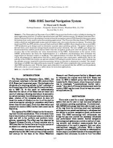
carefully chosen sigma points around the mean. The main idea is to approximate a Gaussian distribution using sample points instead of the mean and covariance. As seen in the block diagram of the system in Figure 1, an unscented Kalman filter is designed to estimate the errors in the calculated system parameters (see Table 1). The system parameters are periodically corrected in order to maintain the best possible alignment for the INS reference trajectory.
• The camera(s) images areas in the environment which contain some stationary objects. • Binocular measurements are available which provide an indication of range to objects in the environment. • The inertial and optical sensors’ relative position and orientation is known. See [15] for a discussion of boresight calibration procedures. The navigation state consists of the following variables, shown in Table 1. The position and velocity components are three-dimensional vectors expressed relative to an Earth-fixed navigation frame. The orientation is expressed using a body-to-navigation frame direction cosine matrix (DCM). Because of the relatively low-quality of the MEMS inertial sensors, both accelerometer and gyroscopic biases are estimated using a first-order Gauss-Markov model. Finally, the three-dimensional position of each landmark is estimated in the navigation frame. In the next section, the implementation of our image-aided inertial navigation system using the UKF is presented. Algorithm Description As mentioned previously, the unscented Kalman filter uses a deterministic sampling approach, specifically the unscented transform (UT) in which the state distribution is represented using a minimal set of
Figure 1: Image-aided inertial navigation filter block diagram. In this filter, the location of stationary objects are tracked and used to estimate and update the errors in an inertial navigation system. The inertial navigation system is, in turn, used to support the feature tracking loop. For the algorithm, the navigation state structure is created to define current system parameters. Since the INS mechanization equations and measurement equations are nonlinear, the unscented transformation is used to compute a collection of sigma points to represent the statistics of the navigation state through nonlinear transformations. Before using a nonlinear function (in the propagation and update cycles), the current navigation state errors (dimension L) and covariance matrix are used to generate a matrix χ of
2L + 1 sigma points. χ0 χi
= =
χi
=
x ˆ (1) p x ˆ + ( (L + λ)Px )i , i ∈ [1, L] (2) p x ˆ − ( (L + λ)Px )i−L , i ∈ [L + 1, 2L] (3)
where x ˆ is the mean vector of navigation state errors, Px is the covariance of the navigation state mean p error vector, ( (L + λ)Px )i is the ith column of the matrix square root and λ is the scaling parameter. The scaling parameter is defined by λ = α2 (L + κ) − L
(4)
where α is a constant value used to determine the spread of sigma points (usually set to 1 ≤ α ≤ 10−4 ). Finally κ is the secondary scaling parameter (usually set to κ = 3 − L) [4]. While the spread of the sigma points is a function of the error distribution, the strapdown mechanization function propagates the whole-valued navigation state, not the errors (see [12]). Hence, once the collection of sigma points χi is computed about the nominal, each sigma point is transformed to and from whole-valued navigation state sigma points, Ni , using a generalized addition/subtraction operation defined as: Ni χi
= N0 + χi = Ni − N0
(5) (6)
For parameters in Euclidian space (e.g., position, velocity, etc.), the addition and subtraction operators are simply standard vector addition and subtraction. Differencing orientation states, namely the Cnb direction cosine matrix, is based on the notion that small angular changes can be appropriately represented by a simple rotation error vector (ψ in the above equations), whereas this is not true for general orientations. This property is exploited in many navigation state error models such as the well-known Pinson error model, which represents angular errors as a threedimensional error vector about some nominal orientation DCM or quaternion. This method is both elegant and efficient. The relative navigation state to error model equations are δpni δvin
= =
pni − pn0 vin − v0n
(7) (8)
Cnb i
=
(I − ψ i )Cnb 0
(9)
δabi
=
abi − ab0
(10)
= =
bbi − bb0 tnij − tn0j
(11) (12)
δbbi δtnij
where ψ i is the angular error ψn ψ i = ψe ψd i
(13)
which corresponds to the i-th sigma point. Thus, given a collection of angular difference sigma points, the whole-valued body-to-navigation frame DCMs can be calculated using the following steps: • Convert the angular errors to the equivalent direction cosine matrix [14]. This represents the orientation error from the estimated navigation frame to the nominal navigation frame. • Multiply this DCM with the nominal body-tonavigation frame DCM. This results in the whole-valued body-to-navigation frame DCM sigma points, represented by Cnb i . After the equivalent whole-valued sigma-points are calculated, they are propagated through the dynamics model, which is in this case the strapdown mechanization equation [12, 14]. ˜ k , wk ] Ni (tk ) = f [Ni (tk−1 ) , u
(14)
˜ k are the inertial measurements and wk is the where u dynamics noise vector. This results in a collection of predicted whole-valued states at the time of the next image (see Figure 2).
Figure 2: Whole-valued navigation state structures are generated using sigma points. These whole-valued states are then propagated through the strapdown mechanization algorithm. Finally, the differences between each predicted navigation state are found by comparing to the nominal, whole-valued navigation state. Given this collection of whole-valued navigation state sigma points, the representative statistics (i.e., mean and covariance) can be calculated. First, the difference between each predicted whole-valued navigation state sigma point is calculated about the nominal navigation state sigma point using the approach
outlined in equations (6) and (7-12). Once the representative error sigma points are determined, the error state mean and covariance are approximated using the weighted average and weighted outer product δˆ x− k
=
2L X
(m)
Wi
χi,k|k−1
(15)
i=0
P− k
=
2L X
(c)
Wi (χi,k|k−1 − δˆ x− k)
based upon the predicted feature locations. This is accomplished by filtering the collection of measured feature locations. Measured features that exceed a statistical Mahalanobis distance are excluded from the correspondence search. In this paper, a 2-σ threshold was applied. If a statistically-unique correspondence set can be determined, the collection of measured fea˜(tk ), is then used to complete the UKF ture locations, z update as follows:
i=0 T δˆ x− k)
·(χi,k|k−1 −
+ Qd
(16)
Pxk ,zk
=
2L X
(c)
Wi (χi,k|k−1 − δˆ x− k)
i=0
where Qd is the process noise. The weights are given by (m) W0
=
W0
(c)
=
(m) Wi
=
λ (17) L+λ λ + 1 − α2 + β (18) L+λ 1 (c) Wi = , i ∈ [1, 2L] (19) 2(L + λ)
where β is a weighting parameter used to incorporate any prior knowledge of the distribution of x. For a Gaussian distribution, β = 2 has been shown to be optimal [4]. The propagated whole-valued navigation state sigma points can now be used to predict the measurement sigma points using the measurement equation zi (tk ) = h [Ni (tk ) , vk ]
(20)
where zi (tk ) is the collection of predicted feature space locations corresponding to the currently tracked landmarks. An illustration of this prediction is shown in Figure 3. Calculating the statistics of the prediction is accomplished in a similar manner as with the navigation errors. The relevant statistics are calculated using the following weighted sum ˆk z
=
2L X
(m)
Wi
zi (tk )
=
2L X
(c)
Wi
= =
δˆ x− z(tk ) − ˆ zk ] k + Kk [˜ − T Pk − Kk Pzk ,zk Kk
(25) (26)
Finally, the estimated error is removed from the nominal navigation state and the update is completed. A conceptual summary of the propagation and measurement cycles for the unscented Kalman filter is as follows: • Based on the current nominal navigation state estimate, calculate a collection of whole-valued navigation states corresponding to the calculated sigma points. • Propagate the set of whole-valued navigation state sigma points through the nonlinear strapdown mechanization function. • Calculate the pre-measurement statistics using the weighted sum of the differences between whole-valued navigation states. • Predict the feature locations of the current landmark tracks. • Determine a statistical correspondence between the predicted and measured feature locations.
(22)
• Repeat as necessary.
ˆk ] [zi (tk ) − z T
=
δˆ x+ k P+ k
• Calculate the statistics of the predicted feature location errors. Use the measurement residual and Kalman gain to correct the nominal navigation state.
i=0
ˆi ] + Rk · [zi (tk ) − z
Kk
(23) (24)
(21)
i=0
Pzk ,zk
T
ˆk ] · [zi (tk ) − z −1 Pxk ,zk Pzk ,zk
where zi (tk ) is the matrix of predicted feature locations at time tk .
SYSTEM TESTS
An important characteristic of the tightly-coupled stochastic feature tracking algorithm is the ability to restrict the feature correspondence search space
As in the previous paper, the UKF-based imaging and inertial fusion navigation algorithm is evaluated using both simulated and experimental ground profiles.
The profiles are designed to provide a range of image types in order to exercise the feature tracking algorithm. The simulation and results are presented in the next section. The data collection system consisted of a consumergrade MEMS IMU and two digital cameras (see Figure 4). The IMU was a Crista consumer-grade MEMS unit (see [3]) which measured acceleration and angular rate at 100 Hz. The digital cameras were both Pixelink A-741 machine vision cameras which incorporated a global shutter feature and a Firewire interface. The lenses were wide-angle Pentax lenses with approximately 90 degrees field of view. The sensors were mounted on an aluminum plate and calibrated using procedures similar to those described in [15]. Images were captured at approximately 2.5 Hz. Although this sensor was not used for this paper, a Honeywell HG1700 tactical-grade inertial measurement unit was co-mounted on the platform in order to provide a one-to-one performance comparison between different grades of inertial sensors.
Figure 3: Stochastic feature projection. Optical features of interest are projected into future images using inertial measurements and stochastic projections.
Simulation The algorithm was tested using a Monte Carlo simulation of a standard indoor profile. The profile consisted of a straight corridor, designed to be similar to the indoor experimental data collection. An accurate simulation of the navigation environment requires simulating the performance of the sensors in response to a true motion trajectory. The trajectory was generated using ProfGen version 8.19 software package [8]. For each Monte Carlo navigation simulation run, the inertial sensor measurements are regenerated using the true trajectory and an inertial sensor error model. Because of the inherent complexity of the optical environment, it is beyond the scope of this paper to generate simulated images. Instead, a simulated feature set was created by randomly distributing features along a corridor surrounding the true trajectory. The features are each given random descriptor vectors in order to exercise the feature tracking algorithm. While this optical simulation method is appropriate for testing the image and inertial fusion algorithm, the results are not directly comparable to the real system performance, because imaging issues such as lighting conditions, motion blur, and affine changes in the feature descriptor due to pose changes are not modeled. In other words, these results are optimistic with respect to position error, however the error divergence trends should still be observable.
Figure 4: Data collection system. The data collection system consisted of a consumer-grade MEMS IMU and monochrome digital cameras. Although not used in this paper, a tactical-grade IMU was co-mounted on the platform in order to provide a performance comparison between different grades of inertial sensors.
Alongtrack Err (m)
1 0.5 0 −0.5 −1
In order to investigate this issue further, the velocity and attitude error plots are shown in Figures 7 and 8, respectively. The velocity errors appear to be very consistent and stable. The attitude errors show a different story, especially in heading error. The obvious heading error bias explains the resulting position error bias. Unfortunately, the cause for this heading error bias is unknown and will require further investigation. As mentioned previously, the apparent stability of the UKF-based algorithm should outweigh the effects of small heading bias for real data seta. In the next section, the experimental data collection
200
300
400
500
600
0
100
200
300
400
500
600
0
100
200
300 Time (s)
400
500
600
Crosstrack Err (m)
0 −0.5 −1 2 1 0 −1
Figure 5: Simulated 60-run Monte Carlo position error results for indoor profile with a consumer-grade inertial sensor using an EKF-based image aiding algorithm. The extended Kalman filter algorithm displays a tendency toward divergence due to the cumulative effects of linearization errors.
North Err (m)
0.4 0.2 0 −0.2 −0.4
0
100
200
300
400
500
600
0
100
200
300
400
500
600
0
100
200
300 Time (s)
400
500
600
East Err (m)
0.2 0 −0.2 −0.4 −0.6 0.2 Vertical Err (m)
The simulated position errors for the EKF and UKF are shown in Figures 5 and 6, respectively. Significant excursions in position are noted in the EKF-based algorithm, which evidence the effects of increased attitude errors resulting in destabilizing linearization errors. In contrast, the UKF-based estimator appears to eliminate the departures and is reasonably consistent with the estimated uncertainty. The UKF estimate does, however, appear to be biased. This is not completely unexpected as the unscented transformation can be shown to produce a biased estimate under non-symmetric nonlinearities. In either case, the effects are relatively small and should be “in-the-noise” when processing real data sets.
100
0.5
−2
A Monte Carlo simulation was conducted using an inertial sensor model representing the Crista consumer-grade IMU. Each simulation consisted of 60 runs, each with randomly generated inertial measurement errors due to random walks, sensor bias, and sensor scale-factor errors. In order to mitigate any potential effects due to the location of the features in the simulated environment, the feature locations and descriptors were randomly generated every 20 runs.
0
1
Vertical Err (m)
The simulated corridor was 3 meters wide, 3 meters high, and approximately 300 meters long. Features were randomly generated on the walls, floor and ceiling of the corridor with an average spacing of 0.25 features per square meter. Each feature was given a random primary length and orientation, which, combined with the true pose of the sensor, resulted in accurately simulated scale and orientation parameters in feature space. After a 60-second stationary alignment, the sensor platform accelerated to 0.5 meters per second, maintained this velocity until the end of the corridor, then accelerated to a stop at the end. The platform remained stationary for 60 seconds after coming to a stop. This resulted in a 660-second image and inertial navigation profile. Simulated images are collected at 2 Hz.
0.1 0 −0.1 −0.2
Figure 6: Simulated 60-run Monte Carlo position error results for indoor profile with a consumer-grade inertial sensor using a UKF-based image aiding algorithm. The UKFbased algorithm shows no indication of rapid divergence, although the estimate appears to contain a bias.
profile and results are presented and compared between the EKF and UKF algorithms. North Err (m/s)
0.05
Experiment
0
−0.05
0
100
200
300
400
500
600
0
100
200
300
400
500
600
0
100
200
300 Time (s)
400
500
600
East Err (m/s)
0.05
0
−0.05
Vertical Err (m/s)
0.05
0
−0.05
Figure 7: Simulated 60-run Monte Carlo velocity error results for indoor profile with a consumer-grade inertial sensor using a UKF-based image aiding algorithm. As expected, the velocity estimates appear consistent and stable.
The algorithm was tested experimentally using a closed-loop ground navigation profile designed to examine the operation of the feature tracking system in a real-world environment and compare the performance between the EKF and UKF implementations. The profile consisted of a closed path in an indoor environment. The path began and ended at the same location and orientation in the Advanced Navigation Technology (ANT) Center laboratory, at the Air Force Institute of Technology. The data collection began with a 10-minute stationary alignment period. After the alignment period, the sensor was moved in a 10minute loop around the hallways of the building. No prior knowledge was provided to the algorithm regarding the location of features or structure of the environment. A sample image from the indoor profile is shown in Figure 9.
Roll Err (mrad)
20 10 0 −10
Yaw Err (mrad)
Pitch Err (mrad)
−20
0
100
200
300
400
500
600
0
100
200
300
400
500
600
0
100
200
300 Time (s)
400
500
600
2 0 −2
2 0 −2
Figure 8: Simulated 60-run Monte Carlo attitude error results for indoor profile with a consumer-grade inertial sensor using a UKF-based image aiding algorithm. The UKF-based attitude estimates appear to be relatively stable and consistent. The source of the heading bias is unknown, however this is most likely the root cause of the position error bias.
Figure 9: Sample image from indoor data collection. The indoor data collection presents the filter with man-made features in an office environment. The crosses and ellipses indicate the locations and uncertainty of currently tracked landmarks. The indoor profile presents the algorithm with different challenges from a feature tracking perspective. The indoor environment consists of repetitive, visually identical features (e.g., floor tiles, lights, etc.), which can easily cause confusion for the feature tracking algorithm. In addition, reflections from windows and other shiny surfaces might not be interpreted properly by the filter and could potentially result in navigation errors. Finally, the lower light intensity levels and large areas with poor contrast (e.g., smooth, featureless walls) presents a relatively stark
feature space. The filters’ estimates of the trajectories are overlayed on a floor plan of the building in Figure 10 for the EKF and UKF algorithms. For both EKF and UKF algorithms, the estimated trajectory generally corresponds to the building’s hallways, with excursions of less than 3 meters. While additional testing is required to fully characterize the performance of the algorithms, the navigation accuracy achieved in a realworld environment indicates promise for the UKFbased image-aided inertial navigation system.
tended Kalman filter. In addition, the unscented Kalman filter maintained an accurate, and consistent position error estimate. One potential drawback of the UKF for this application was the presence of a systematic bias in the position and attitude estimates. While this could be an issue for some applications, we believe the greatly improved stability performance greatly outweighs the small bias effects for a large majority of applications. DISCLAIMER The views expressed in this article are those of the author and do not reflect the official policy or position of the United States Air Force, Department of Defense, or the U.S Government. References [1] A. Brown and Y. Lu. Performance Test Results of an Integrated GPS/MEMS Inertial Navigation Package. In Proceedings of ION GNSS 2004, pp. 825–832, September 2004.
EKF UKF
Figure 10: Estimated trajectory for the extended Kalman filter (blue) and unscented Kalman filter (red) image-aided inertial algorithm. Both algorithms demonstrate similar performance, within the expected uncertainty of the position state estimate.
CONCLUSIONS Previous research presented a statistically rigorous method to tightly couple imaging and inertial sensors using an extended Kalman filter. Unfortunately, the estimator demonstrated divergent characteristics during longer-term navigation profiled which was attributed to the cumulative destabilizing effects of linearization errors. To address this known weakness of the extended Kalman filter, an image-aided navigation algorithm based on the unscented Kalman filter was designed. The filter was evaluated and compared using a combination of simulated and experimental data. During the evaluations, the stability of the unscented Kalman filter was shown to significantly outperform the ex-
[2] R. G. Brown and P. Y. Hwang. Introduction to Random Signals and Applied Kalman Filtering. John Wiley and Sons, Inc., New York, NY, 1992. [3] Cloud Cap Technology. Crista Inertial Measurement Unit (IMU) Interface / Operation Document. Specification, May 2004. URL: http://www.coudcaptech.com/. [4] S. Haykin. Kalman Filtering and Neural Networks. John Wiley and Sons, Inc., New York, NY, 2001. [5] S. J. Julier and J. K. Uhlmann. A New Extension of the Kalman Filter to Nonlinear Systems. In Proc. of AeroSense: The 11th Symp. on Aerospace/Defence Sensingm Simulation, and Controls, 1997. [6] S. J. Julier and J. K. Uhlmann. Unscented Filtering and Nonlinear Estimation. Proceedings of the IEEE, 92(3):401–422, March 2004. [7] C. Liebe. Star trackers for attitude determination. Aerospace and Electronic Systems Magazine, IEEE, 10(6):10–16, June 1995. [8] S. Musick. Profgen: PC Software for Trajectory Generation. Software Package v8.19, Air Force Research Laboratory, Wright-Patterson Air Force Base, Ohio, January 2004. [9] P. Pissavin, J. Krebs, P. LeLong, P. Vidal, and R. Navoni. Improved Star Tracker for ODIN
Satellite. In Proceedings of ESA International Conference on Spacecraft Guidance, Navigation and Control Systems, pp. 611–616, November 1997. [10] D. Purll, N. Gradmann, and M. Bollner. The ROSAT Star Tracker: Flight Experience. ESA, Spacecraft Guidance, Navigation and Control Systems, N92-2443215-18:551–556, 1991. [11] J. F. Raquet and M. Giebner. Navigation Using Optical Measurements of Objects at Unknown Locations. In Proceedings of the 59th Annual Meeting of the Institute of Navigation, pp. 282–290, June 2003. [12] E. Shin and N. El-Sheimy. Unscented Kalman Filter and Attitude Errors of Low-Cost Inertial Navigation Systems. Journal of the Institute of Navigation, pp. 1–9, 2007. [13] D. Strelow and S. Singh. Optimal Motion Estimation from Visual and Inertial Measurements. In Proceedings of the Workshop on Applications of Computer Vision, December 2002. [14] D. Titterton and J. Weston. Strapdown Inertial Navigation Technology. Peter Peregrinus Ltd., Lavenham, United Kingdom, 1997. [15] M. J. Veth and J. F. Raquet. Alignment and Calibration of Optical and Inertial Sensors Using Stellar Observations. In Proceedings of ION GNSS 2005, pp. 2494–2503, September 2005. [16] M. J. Veth and J. F. Raquet. Fusion of LowCost Imaging and Inertial Sensors for Navigation. In Proceedings of the Institute of Navigation GNSS 2006, pp. 1093–1103, September 2006. [17] M. J. Veth and J. F. Raquet. Two-Dimensional Stochastic Projections for Tight Integration of Optical and Inertial Sensors for Navigation. In Proceedings of the Institute of Navigation National Technical Meeting, pp. 587–596, 2006. [18] M. J. Veth, J. F. Raquet, and M. Pachter. Stochastic Constraints for Efficient Image Correspondence Search. IEEE Transactions on Aerospace Electronic Systems, 42(3):973–982, July 2006.