poro-elastic medium at t = 0.025 s. (b) The CGFEM using the Newmark method. Fig.8 The shear stress distributions in the square panel of a saturated poro-.
ACTA MECHANICA SINICA, Vol.20, No.l, February 2004 The Chinese Society of Theoretical and Applied Mechanics Chinese Journal of Mechanics Press, Beijing, China Allerton Press, INC., New York, U.S.A.
TIME
DISCONTINUOUS FOR
ISSN 0567-7718
GALERKIN
FINITE
DYNAMIC ANALYSES PORO-ELASTO-PLASTIC LI Xikui ( ~ N ~ ) t
IN
ELEMENT
METHOD
SATURATED MEDIUM*
YAO Dongmei ( ~ . ~ )
(The State Key Laboratory for Structural Analysis of Industrial Equipment, Dalian University of Technology, Dalian 116024, China) A time-discontinuous Galerkin finite element method for dynamic analyses in saturated poro-elasto-plastic medium is proposed. As compared with the existing discontinuous Galerkin finite element methods, the distinct feature of the proposed method is that the continuity of the displacement vector at each discrete time instant is automatically ensured, whereas the discontinuity of the velocity vector at the discrete time levels still remains. The computational cost is then obviously reduced, particularly, for material non-linear problems. Both the implicit and explicit algorithms to solve the derived formulations for material non-linear problems are developed. Nmnerical results show a good performance of the present method in eliminating spurious numerical oscillations and providing with much more accurate solutions over the traditional Galerkin finite element method using the Newmark algorithm in the time domain. ABSTRACT:
K E Y W O R D S : time discontinuous Galerkin FEM, saturated porous medium, seepage-dynamics coupling, wave propagation, elasto-plasticity
i
INTRODUCTION
The discontinuous Galerkin finite element method (DGFEM) has attracted much attention and many studies in solving time-dependent problems such as structural dynamics and wave propagation problems[ 1~9]. The essential features of the method can be summarized in the following three aspects. The finite element discretizations are used in both space and time simultaneously. The assumed nodal primary unknown vectors and its derivatives with respect to time for the semi-discrete field equation are independentIy interpolated by piecewise polynomial functions in the time domain. In addition, both of them may be discontinuous at t h e discrete time levels. The traditional (continuous) Galerkin finite element method (CGFEM) used for time-dependent problems is mainly characterized by its semi-discrete
procedure. The field equation is discretized using finite elements in the spatial domain and the semidiscrete field equation in turn is discretized using finite difference methods in the time domain such as the Newmark method. C G F E M can usually obtain sarisfactory results for time dependent problems in which the low frequency response dominates. However, it generally fails to properly reproduce sharp gradients of the solution in space, particularly, fails to capture the discontinuity across the traveling wave front, to filter out the effects of spurious high frequency modes and to control spurious numerical oscillations as impulsive waves propagate in a medium where the stress normM to the surface of the wave front is discontinuous across it. In contrast with CGFEM, D G F E M possesses the possibility to filter the spurious oscillations and provides much more accurate solutions than does C G F E M using the Newmark method for the simulation of the wave propagation with such a
Received 28 May 2002, revised 17 April 2003 * The project supported by the National Natural Science Foundation of China (19832010, 50278012, 10272027) and the National Key Basic Research and Development Program (973 Program, 2002CB412709) t E-maih xikuiliQdlut.edu.cn
Vol.20, No.l
Li XK & Yao DM: Time Discontinuous FEM for Dynamics in Porous Medium Subgrade
wave front and with the same time step size. Though, on the other hand, the existing D G F E M formulations typically lead to a system of coupled equations with number of total equations four times larger than that generated by C G F E M using the Newmark method, it is indicated that [5] as D G F E M is third-order accurate, a larger time step may be used in its implicit algorithm. In addition, we may use its explicit algorithm to avoid directly solving the system of coupled simultaneous equations. Hence, the total computational cost of D G F E M may be still comparable with that of CGFEM. It is remarked that for C G F E M it is only required to determine the nodal primary unknown vectors at the end of each incremental time step whereas for D G F E M the nodal primary unknown vectors have to be determined at both the beginning and the end of each incremental time step. For the material nonlinear dynamic problems in a poro-elasto-plastic medium this disadvantage of D G F E M will result in dramatic increase of computational efforts to enforce the yield criterion at each local integration point and satisfy the non-linear global system of semi-discrete governing equations at the two time instants simultaneously. In the present work a new version of D G F E M formulations is developed on the basis of the proposed weak form of semi-discrete dynamic equations in the time domain for a saturated porous medium. The primary unknown vector (displacement vector) and its derivative with respect to time (velocity vector) are taken as independent variables and both of them may be discontinuous at the discrete time levels. In contrast with the existing D G F E M formulations in which a piecewise linear interpolation approximation is used for the discretization of displacements and velocities in the time domain the proposed D G F E M formulations are characterized by the specific P3-P1 interpolation scheme with piecewise cubic (Hermite's polynomial) and linear interpolations for displacements and velocities, respectively. As a consequence, the continuity of the displacement vector is automatically ensured at each discrete time level and discontinuity of the velocity vector at discrete time levels still remains. This is the main advantageous feature of the proposed D G F E M over the existing D G F E M formulations, in which both displacements and velocities are discontinuous at discrete time levels. Consequently, the iterations to enforce nonlinear constitutive relations at local integration points, the reformation of elasto-plastic tangent stiffness matrices and the recalculation for the internal force vectors in the present
65
D G F E M formulations are only required at the end of each incremental time step. This feature makes the new proposed DG formulations have the advantage over the existing DG time-space elements in reducing computational cost, particularly for material nonlinear dynamic problems. Following the developed new version of DG formulations, both the implicit and explicit algorithms to solve the proposed DG formulations are presented. The algorithms are applied to the dynamic analyses in an elastoplastic saturated porous medium subjected to impulse loads. For high speed motion phenomena, typical of wave propagation in soils, all acceleration terms in the equations of motion of the saturated porous medium can not be neglected. As the porous fluid is compressible, the linearized form of the semi-discretized systems (discretized in the spatial domain) of the equations governing the motion can be written as
M~l(t)+C~t(t)+Kd(t) = re(t)
t E I = (0, T) (1)
where M is the mass matrix, C the viscous damping matrix, K the stiffness matrix, f e the vector of applied forces, and d, ~/, d are the displacement, velocity and acceleration vectors, respectively. I is the time domain. Equation (1) can be expanded and particularly expressed as [1~
[0
M~
I-ClW2 On
K11
--C12 K12
]
(2)
K5 where
Ms
=/~ N~(1 -
n)p, SN~dn
M / = /ca N~:np/SNULdO - 1 N~d u f2 Cu =/~ N~n 2 5k~,
Cn = fo N~'n25kj'lN~da2
K n = K t + K~I
Ktij =/a NK'kDikflN~'*df2
(3)
ACTA MECHANICA
66
"
Kllij
=
L
respectively. For clarity, Eq.(6a) is rewritten with omission of the superscripts of the vectors d +, d~+l, v +, v ~ + l a n d the time variable t in the equation as
N~,~(a - n)2QN~,jd~2
K12ij - = / ~ N~z,in(a
-
n)QN~,jd~?
d = dnN1 + dn+lN2 + ruM1 + Vn+lM2
K22ij = f 9 N~,in2QN~,,jd~? 1
n
o~ - - n
Q
Kf
K~
2004
SINICA
u, ~, ~ and U, b, ~ are the nodal displacements, velocities and accelerations of the solid skeleton and the nodal intrinsic displacements, velocities and accelerations of the pore fluid, respectively, P8 and pf are the densities of the solid and fluid phases, K f and Ks are the bulk moduli of the fluid and the solid materials, n is the porosity, kw is the Darcy permeability coefficient, a is the Biot parameter, Dijkl is a fourth order tensor defining a constitutive law for the solid skeleton, N~,j, Nu,j are the spatial derivatives of the shape functions of the K - t h node with respect to the j-coordinate axis for the spatial finite element discretization.
2 A N E W V E R S I O N OF F O R M U L A T I O N S FOR TIME DISCONTINUOUS FINITE ELEMENT METHOD Let I = (0, T) be a partition of the time domain, having the form: 0 < tl < " " < t n ~ t n + l ~ "'" tN = T. D G F E M permits discontinuities of functions at discretized time levels. For a typical time instant tn, the temporal j u m p of the function w(tn) = wn can be expressed as [[w~]] = w( t +) - w( t S )
(4)
w(t~) = lim w(t~ + e)
(5)
(6b)
It is assumed for the current time step t h a t the global nodal displacement and velocity vectors d ~ , v ~ at time t~ have been determined at the end of the previous time step. The Hermite interpolation functions used in Eq.(6b) are N1 ----N l ( t ) ----A2(A1 + 3A2) (7)
N: = N:(t) = ~ ( ~
+ 3~)
M1 = M l ( t ) = A2A2At
(s)
M2 = M2 (t) = - A1A~ At in which A1-- tn+l -- t At
A2 -- t -- tn At
(9)
T h e temporal derivative of the p r i m a r y unknown
voodoo,
volocityvoc o
{ V u } , at ar-
bitrary time t E [tn, tn+l] is interpolated as an independent variable by linear time shape functions as
v(t) = Vn+Al(t) + V~+IA2(t )
(10a)
or simply expressed as V = V n A 1 "~- V n + I A 2
(10b)
As the vectors of the nodal displacements d and velocities v vary independently in the following variational equation in the time domain I,~ = (t~,t~+l) , Eq.(1) is re-expressed as
where
MiJ + C v + K d = fr
(11)
e--+O•
Denote I~ -- ( t ~ , t ~ + l ) as a typical incremental time step with the step size At = tn+l - - t n 9 The p r i m a r y unknown vector (the global nodal displacement vector) of the semi-discretized Eq.(1) at time t E [t~,tn+l] in the current time step In is interpolated by third order (Hermite) time shape functions as
d(t) = d+Nl(t) + d~+lN2(t)+
+Ml(t) + S+lM (t)
with the constraint condition
~/-v=0
(i.e./t-v~=0
0-Vu=0)
The weak forms of the semi-discretized E q . ( l l ) and the constraint condition (12), along with the discontinuity conditions of d and v on a typical time s u b - d o m a i n / i , can be expressed as
~n
5vT(MiJ + C v -F K d - f f ) d t +
(6a)
- 1 stand for the global nodal where d ,+, d,+l, v +, vn+ displacement and velocity vectors at times t n, + t~+l,
(12)
fz,~ 5dT K(cl - v)dt + 5dT K[[d~]]+
Vol.20, No.1
Li XK & Yao DM: Time Discontinuous FEM for Dynamics in Porous Medium Subgrade
5vTM[[v,~]] = 0
(13)
6Vn+l the following matrix equation for solving dn, dn+l, Vn, Vn+l (i.e. d +, d-~+l,v+,v~+l) by means of d~, v~ and F~, F~ representing the incremental external loads within [t+, t~+i]
Substituting Eqs.(6) and (10) into Eq.(13), we obtain from independent variations of 5d~, 5dn+i, 5v,~,
1_K 2
1_K 2
At K 4
At K
1_ K 2
1_K 2
_At K 4
At K 4
At g 4
At g 4
1M At C 2 +3
At K 4
At K 4-
1M At At2 K 2 + ~ - C + 12
in which
_1M
2
i-T
Atc
=
0
v~
F~I + M v n
v,,+i
F~
+3
(14) = f ne A1 ~-
(15)
P
F~ = / .
d~+i At2 K
At
+yc1M
f F~ = [ . ~if~(t)dt d/ n
67
A2fe(t)dt
e A2 fn+l
(16)
where fe(tn), fe(t~+i ) are the nodal external force vectors at times t~,G~+i. Substitution of expression (16) into expression (15) gives
dl
At e
It is assumed that the nodal external force vector of the system varies within the incremental time step/:~ E (tn,t~+i) in the linear form, i.e.
fe(t)
K
--
ff(t~)Ai + ff(t~+i)),2
0
0
0
0
0
0
-
AtK 2 A t C _ At2 K 6 12
12
At M+~-C+
A2 t c + A3t 2 K
M
(i.e. d + = d~)
zxt + -r
/kt2 K
At C
-2-
zxt2 12 K
+
3
d~+i
A6t 2 K IJ
Kd~
=
v~
F~I - F~ + M v ~
V~+l
F~I + F~ + M v ~ - A t K d S
(is)
This is the basic matrix equation of the time discontinuous Galerkin finite element method derived in the present paper. The solutions for nodal displacement vectors dn,d~+l are uncoupled from those for nodal velocity vectors v~, v~+i. Equation (18) can be further written as
d,~ = d~
F~ = y f ~
(i7)
At + yf~+~
0
--AtK 2 At At2 K M + ~-C
r
Equation (14) can be recast as follows
0
K
At
At
(19a)
ixt C _ zxe K 6 12 Z~t C
M+~-
At2 K
+~-
] | [ J
{ vn } { = v~+i
F~-F~+Mv~ F~ + F~ + M v ~ - A t K d ~
} (19b)
d~+l = d~ + ~At(v~ + v~+i)
(19c)
It is remarked that, thanks to the piecewise P3-P1 interpolation approximations for displacements and velocities used in the present DGFEM formulations, the continuity of the nodal displacement vector dn at any time level t~ in the time domain I = (0, T) is automatically ensured. It is only the nodal velocity vectors at discretized time levels that remain dis-
68
ACTA MECHANICA SINICA
continuous. Obviously, this is a significant advantage, particularly for material non-linear problems, over the existing D G F E M formulations, in which both nodal displacements and velocities at both ends of a typical time step, i.e. at times t~ and tn+l, are discontinuous. We will stress this advantage later when we apply the present DGFEM formulation to elasto-plastic problems in a porous medium. 3
SOLUTION TO-PLASTIC
PROCEDURES DYNAMIC
FOR ELASPROBLEMS
where
j f i --_K(t~)6d
=
f~(t)
t E I = (0, T)
f
F~ = [_ Alfi(t)dt dl n
F~ = f
A2fi(t)dt
and assuming that the nodal internal forces vary within the incremental time step Is E (tn,tn+l) in the third order (Hermite) form as i t =) f~(
i li(t,~)N~ +/~(tn+~)N2+ .i )iu(t )M + f.(tn+
(20)
)M2
i N 2+ = I~,~N~ + $~,~+~ 9i
M
9f~,n
Cv(t) + Kd(t)
(27)
,]1 n
For the linear case, the nodal internal force vector is degenerated into its linear form fi(t) =
(26)
Defining
To deal with non-linear dynamic problems, Eq.(11) is re-written as
Mio(t) + fi(t)
2004
.i
M
l+fu,n+l
(28)
2
(21) in which fi(tn) , fi(t,~+l ) are the nodal internal force
in which the nodal internal force vector is composed of two parts, i.e. the viscous damping forces and the stiffness resisting forces. For the elasto-plastic case, in consideration of the definitions of both the stiffness matrix and the nodal displacement vector given in Eq.(3), the nonlinear internal force f(t) resisting the elasto-plastic deformation of the solid skeleton can be separated from the linear parts of f ( t )
$i(t) = cv(t) + K e d ( t ) +
9i
.i
vectors at times tn, t~+l, and f (t~), f (t,~+l) are their derivatives with respect to time, we obtain by substituting Eqs.(22), (24), (28) into Eq.(27) that F~ = -~C(2vn
+ v~+l)+
KQ(7Atd~+3Atdn+l+ vn
20
(22)
-- "-'~ -vn+l)
~-
u
(29)
0
=
in which
Kq(3Atd~+7Atd~+l+
(23) K Q = L KT2
+ 2vn+l)+
K22
/,t 2
f i~,j(t)
i t j=l
BWa"(t)d~?j
= "=
30
(24)
J
{EL}
0
(30)
where
Ne is the total number of elements, fu,j (t) is the nodal internal force vector of the j - t h element, B and (r'(t) are the strain-displacement matrix and the generalized effective stress vector for the solid skeleton, respectively. The weak form of DGFEM within a typical time step In for the elastoplastic dynamic problem can be written as
Flu =
gfiT(d--v)dt+
Fi2~ = f
= 0
(25)
A2fi(t) dt
,,]1 n
can be expanded to the detailed forms
N~
3
J
f
--At20 JYz~BW~
jdT K(t~)f[d~]] + JvT M[[vnl]
i Axfu(t)dt (31)
j=l
~ 5vT(Mv+fi-f~)dt+~
/,t
vn - ~-v~+l) +
At 2 j . + ~--kep'nVu'j(tn)-
Li XK & Yao DM: Time Discontinuous FEM for Dynamics in Porous Medium Subgrade
Vol.20, No.l
At2 J (tn+l)] 30 kep'n+lVu'J
(32)
No
= 0
7At [
Ja5
J~
BZo.,, +~d~. + A? 5
~-kep'nVu'j(tn)-
At 2 j (tn+l) ] 20 kep'n+lVu'j
(33)
where k jep,n, kep,n+l J are the tangent elasto-plastic stiffness matrix of the j - t h element at tn, t~+l. Substituting Eqs.(6), (10), (22), (27) and (28) into Eq.(25), we obtain the following equations from independent variations of 5dn, 5d~+1, 5v~, 5Vn+ l
+ < + i ) - At
For a typical time step In, the linearization assumption is used for the elastoplastic dynamic problems to obtain the initial predictors d~ = d-~ - 0 v on+l,an+l ao n l,'On, in the initial iteration (j = 0) with the use of Eq.(19). In general, Eqs.(35c) and (35d) will not be satisfied within an error tolerance with the initial predictors. The residual vectors R{ and R j for Eqs.(35c) and (35d) in the j - t h iteration can be expressed as 9
At
9
R~ = MVJn + - ~ C ( v ~ - Vn+I)-}j
KQ[-~-(d n -- dn+l) J -}- -At2 . "k-./jjn_l_1) ] 2t_ ~ - (VJn
+ v +l) - d~] = o
{F~ j - p i ' j
(34a)
}
--2~
K[l(-dn
At -]- dn+l)--'-~-(Vn -]-Vn+l)] ~---0
(34b)
K (34c)
rat d
Q[~-(
J At2 J n -4- dn+l) -~ --~-(v j - Vn+l)]-4-
(F~ + Y~) - M v ~ ( r
0
At2 " v,~+l)] = 0 K [ ~ o (dn - d n + l ) + ~ - ( , v n +
0) (37)
With the use of the Newton-Raphson process, we have (34d)
It is noted that the subscript of the matrix K
in
Eq.(34) is omitted for clarity, i.e. K = K ( t ~ ) = K ~ . The DG finite element formulations for the elastoplastic dynamics can be obtained by using Eq.(34) as follows d~ = d n
(35a)
dn+ 1 : dn -]- ~ ~t(v n Jr-Vn+l)
(355)
/I//
At
+-K
C
At 2
- 12
At C
Kt
At C _ At 2 K t 2 3 Q
- Vn+l) -}- K Q L5|--v(d~ - d n + l ) +
]
9 At C At2 K t | M-e~- 7 QJ
(38) AVn+ 1
-R~
where
= [
F~
At2 K t
Q
[ K ~ I + Ktep
A
O)
J 2C(vJn -~ Vn+l)-~-
{ ~I'J 1~I1'3} _ -1. + -2.
+ ~n+l) + F~ - F ~ +
At. Mvn + 6C(v~
Mv~(r
(36)
= M V nJ+ 1 +
9
At2 ] 20 (v~ + v~+x) - M v ~ = 0
_ (Y~ - Y~) -
0
R~
~-M(-~.
(35d)
3.1 I m p l i c i t A l g o r i t h m
j=l L20
20
(F~ + F~) - Mv~
69
K12 ]
K5
N~
(39)
te' = E k'e, /=1 60 (v~ + V,~+I ) -]-
0
--
(F~ - F~) - M v ~ = 0 MV~+l
At
(35c) At
-] - ~ C ( v n -]- Vn+l) -[- K Q [ ~ - ( d ~ + dn+l)-]-
12 ('~ - ,,~+1) +
Fil~ +o Fi~
-
K S is the global tangent stiffness matrix at the current time step, klep is the tangent elasto-plastic stiffness matrix of t h e / - t h element. An iterative computation algorithm for a typical time step In can be given as follows: (1) dn -~- d n 9 O (2) j = 0, compute predictors _0 v~, V0~+1, Ja~+l by using Eq.(19).
ACTA MECHANICA SINICA
7O
(3) Loop for j - t h iteration: (a) Computations for elastoplastic constitutive relations and nodal internal forces. Loop for each integration point in each spatial finite element Compute ( r " ( d J + t ) according to the elastoplastic constitutive model and the nodal internal force vector ~i,j ., u.n+ l -- ~ BW~,,(dj+l)df2" Compute F~ 'J,F ; '3 by using Eqs.(29)~(33).
Endloop (b) Compute the residual vectors R~, R~ according to formulae (36) and (37). (c) Check for convergence of the j-th iteration if IIR~]I < R TOL and IIR~II < ~TOL, terminate the iteration loop. (d) Proceed the next iteration in the loop and j Avn+J 1 by using Eq.(38). calculate Avn, (e) Update the predictors and compute the j-th correctors, j ~ j d- 1
=
+
j--1 j J Vn§ = v,~+l + Avn+l 1
(40)
j
j
d{+~ = d ; + ~ZXt(v~ + Vn+l) go to (a). It is worth noticing that in contrast with the existing DG finite element formulations, in which d~ r d~, the feature of the present DG finite element formulation d~ - d~ enables to save half of the computational cost in the most time-consuming P
computation sub-step (a) as f i , ~ = / ~
BTG"(d~)d/2
has been determined in the last time step. This is the prominent advantage of the proposed version of D G F E M over the existing DG formulations.
2004
KQ[~-(dn
At2 v vn+l)] +dn+l)+--~( n--
+0 dn = d n
+
-(fn +/e+l)
(42)
1 dn+l = d~ + ~ A t ( v ~ + v,~+l) (43)
As an explicit solution algorithm, the mass matrix M in Eqs.(41) and (42) is lumped. As it is noted i in Eqs.(32), (33) depend on the unthat F liu , F~u known vectors vn, Vn+l, d,~+l , the iterative process for the explicit algorithm described by Eqs.(41)~(43) is required. 4
NUMERICAL
RESULTS
In this section two examples are presented to demonstrate the performance of the proposed discontinuous Galerkin finite element formulations in dynamic problems in a linear/non-linear saturated porous medium subjected to impulse loads. The problems are characterized with the dominating high frequency response and the propagation of discontinuities or sharp gradients of the solution. Since there are no analytical solutions available of this type of 2D problems, we first consider a one dimensional stress wave propagation problem in a saturated porous medium, for which the analytical solution in elasticity exists. We consider a column of a saturated porous medium with cross section A = 1.0m 2 and length L = 50m. At the fixed end of the column ux = Ux = u u -- Uy = 0 is specified, which implies the enforced undrained boundary condition. The column loaded at its free end by the axial force impulse P with the force history given in Eq.(44) is analyzed as a plane strain problem, as shown in Fig.1. 4.0 x 10³ kN
t C [0, 0.04 s]
0
t > 0.04 s
P(t) =
(44)
3.2 E x p l i c i t A l g o r i t h m An explicit solution algorithm can be derived from Eqs.(35c), (35d), (17), (29)~(31) and given by
[ 0
Mvn = Mv~
At - -~C(vn
- vn+l)--
FAt d At2 K Q i--g-( ~ - d,~+l) + ~ - ( v n
0
MVn+l = Mv~
+
~- y ( f n
-- f e d - s )
- ~A t c - ( v ~ +
v,~+l)-
I(
L
Vn§ ]J
Ic (41)
--
)
P
X
,I
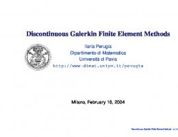
(a) The structure diagram Fig.1 An uniform elastic or elasto-plastic saturated column with one end fixed subjected to a rectangular impulse load applied to the another end
Li XK & Yao DM: Time Discontinuous FEM for Dynamics in Porous Medium Subgrade
Vol.20, No.1 P
71
at two t i m e levels of t l = 0.06s a n d t2 = 0.14s. T h e t i m e s t e p size A t = 1 x 1 0 - 3 s is used. C o m p a r i s o n s of t h e n u m e r i c a l results w i t h t h e a n M y t i c M s o l u t i o n s are also given in Fig.2.
4 000kN
2000 1 000 t=O.O4s
0
t
--I 0 0 0
(b) The load history
--DO - - - DO ..... DG ..... D G
-2ooo
Fig.1 An uniform elastic or elasto-plastic saturated column with one end fixed subjected to a rectangular impulse load applied to the another end (continued)
- 3 000
DCVD, DCVD, DDVD, DDVD,
stress pr 9169 stress ptess~r
....... ~alytical, pr~s~
- 4 000 0
10
20
30
40
50
60
x/m
T h e m a t e r i a l p r o p e r t y d a t a are as follows: E = 1.0 • 105 k P a , p~ = 2 500 k g / m 3, K s = 1.385 x 10⁵ k P a , v = 0.3 for t h e solid p h a s e a n d k~ = 1 x 10 - 6 m / s , pf = 1 0 0 0 k g / m 3, K I = 2.0 x 1 0 4 k P a for t h e fluid phase. T h e p o r o s i t y is n = 0.2. F o r t h e e l a s t o - p l a s t i c r e s p o n s e of t h e s a t u r a t e d c o l u m n , t h e p l a s t i c y i e l d beh a v i o r of t h e m a t e r i a l is a s s u m e d to o b e y t h e D r u c k e r P r a g e r criterion. T h e linear s t r a i n h a r d e n i n g rule c = co + hp~ p for t h e cohesion is used for t h e e v o l u t i o n of t h e e l a s t o - p l a s t i c b e h a v i o r . Here co, h~, Cp are t h e i n i t i a l cohesion, t h e strMn h a r d e n i n g p a r a m e t e r a n d t h e equivalent p l a s t i c s t r a i n [n] defined for t h e pres-
(a) Comparisons among DG_DCVD, DG_DDVD and AM at t = 0.06 s
2000 i000
o --I 0 0 0
-2000.
--3 0 0 0
20
N
9
CG
N
9
~al~r
000 0
sure d e p e n d e n t e l a s t o - p l a s t i c m a t e r i M s , respectively. I n t h e p r e s e n t e x a m p l e Co = 10 k P a , hpC = 1 k P a , t h e i n t e r n a l frictional angle r = 15 ~ a n d t h e p l a s t i c pot e n t i M angle r = 5 ~ F i r s t we consider t h e elastic case. The s p e e d of t h e c o m p r e s s i o n wave is given b y c = V / ( A + 2 G + Q ) / p ~ 3.0 x 1 0 2 m / s , in which )~ is
10
CO
- - -
....
-4
~l~l#r
str9 prcssm* s~ss prcss~*
- -
U 30
40
50
6O
x/m (b) Comparisons between C G F E M and AM a t t = 0 . 0 6 s
2 000 Cr
L a m e p a r a m e t e r a n d G is t h e s h e a r m o d u l u s , p is defined as t h e d e n s i t y of t h e solid-fluid m i x t u r e , n a m e l y p = npf + (1 - n)p,. T h e d i s p l a c e m e n t s for b o t h t h e solid a n d t h e fluid phases in t h e y axis for all nodes are a s s u m e d as fixed, i.e. uv = Uy = 0, which implies t h a t t h e r e are n e i t h e r l a t e r a l d e f o r m a t i o n nor l a t e r a l d r a i n a g e for t h e column. To c o n s i d e r t h e u n d r a i n e d c o n d i t i o n , t h e d i s p l a c e m e n t s for b o t h t h e solid a n d t h e fluid p h a s e s in t h e x axis are a s s u m e d to b e b o u n d for all nodes, i.e. u~ = U~. T h e a n a l y t i c a l solutions of t h e p r e s e n t elastic case consist of two r e c t a n g u lar waves t r a v e l l i n g along t h e c o l u m n axis w i t h t h e l e n g t h of 12 m, (r'~ = - 2 719.48 k P a for t h e effective stress a n d p = 1 280.52 k P a for t h e p o r e pressure. Figure 2 i l l u s t r a t e s t h e r e s u l t i n g wave p r o p a g a t i o n solutions o b t a i n e d b y t h e p r e s e n t D G _ D C V D , t h e existing D G _ D D V D a n d t h e C G _ N e w m a r k m e t h o d for t h e effective stress in t h e c o l u m n axis a n d t h e p o r e p r e s s u r e
1000 o - 1 000
~- - 2 o o o
-~ --3 000
- - - -
D G D C V D , stress DO DCVD, prtss~r
..... .....
D G D D V D , ~xcss DG DDVD, ~r162
.......
~81ytlcal,pr~s~c
--4 000 0
10
20
30
40
50
60
X/Ill
(c) Comparisons among DG_DCVD, DG_DDVD and AM at t = 0.14s Fig.2 The propagation of rectangular compression waves in the saturated poro-elastic column in an undrained condition. Comparisons of the effective stress and the pore pressure wave shapes among DG_DCVD, DG_DDVD, C G F E M and the analytical method (AM)
ACTA MECHANICA SINICA
72 2000
inclined i m p u l s e c o m p r e s s i o n l o a d at t h e t o p left corner A d e p i c t e d in F i g . 5 ( a ) . T h e e x a m p l e is a n a l y z e d as a p l a n e s t r a i n p r o b l e m . G e o m e t r y , b o u n d a r y cond i t i o n s a n d t h e finite e l e m e n t m e s h w i t h 50 • 50 elem e n t s a r e also given in t h e figure. T h e l o a d i n g h i s t o r y of t h e i m p u l s e l o a d P is i l l u s t r a t e d in F i g . 5 ( b ) . T h e
r,-,q-~,l~,%,v
1000
t
t
o
-1000
d -2000
- -
C~_N~wraalk, s~r*ss CO_N 9 prcs~ mal~cal, ~9 ..... ~ a l y t l e a l , p r ~ s ~ r
---
--3 000
2004
.....
- 4 000 0
10
20
30
40
50
60
2000 a~
1000 X / II1
0 (d) Comparisons between C G F E M and AM at t = 0.14s
(D
-i000 --2 000 - -
Fig.2 The propagation of rectangular compression waves in the saturated poro-elastic column in an undrained condition. Comparisons of the effective stress and the pore pressure wave shapes among DG_DCVD, DG_DDVD, C G F E M and the analytical method (AM) (continued)
--3 000
g o o d p e r f o r m a n c e of t h e p r o p o s e d D G _ D C V D a n d t h e e x i s t i n g D G _ D D V D m e t h o d s over t h e C G _ N e w m a r k m e t h o d is obviously observed. F i g u r e 4(c) i l l u s t r a t e s t h e d e v e l o p m e n t of t h e equivalent p l a s t i c s t r a i n occ u r r i n g at t h e free e n d of t h e c o l u m n w i t h r e s p e c t to time. I t s h o u l d b e r e m a r k e d / t h a t d u e to i n c a p a b i l i t y of filtering out t h e high f r e q u e n c y m o d e s , t h e s p u r i o u s n u m e r i c a l oscillation o c c u r r i n g at t h e free e n d after t h e wave t a i l passes in t h e n u m e r i c a l solut i o n b y t h e C G _ N e w m a r k m e t h o d r e s u l t s in a spurious f u r t h e r d e v e l o p m e n t of t h e equivalent p l a s t i c s t r a i n . Hence, t h e e x t e n t of p l a s t i c y i e l d i n g p r e d i c t e d b y t h e C G A N e w m a r k m e t h o d is w r o n g l y m u c h over estimated. A s t h e second e x a m p l e , we c o n s i d e r t h e elastic wave p r o p a g a t i o n in a t w o - d i m e n s i o n a l s a t u r a t e d p o r o u s m e d i u m . A s q u a r e d o m a i n is s u b j e c t e d to a n
DCVD, DG_DDVD,
set~ p~mmr sax~
- - - DG_DDVD, p t ~ s ~ c
-4
000
0
10
20
30
40
50
60
x/m (a) Comparisons between D G I ) C V D and DG_DDVD at t = 0.06 s
T h e n t h e e l a s t o p l a s t i c case is c o n s i d e r e d for t h e s a t u r a t e d p o r o u s column. T h e c o l u m n is l o a d e d a t its free e n d b y t h e a x i a l force i m p u l s e P w i t h t h e force h i s t o r y given as Eq.(44). Uy = 0 a n d free u u for all n o d e s are a s s u m e d to s i m u l a t e t h e l a t e r a l deform a t i o n a n d d r a i n e d c o n d i t i o n of t h e column. M e a n while, t h e d i s p l a c e m e n t s of b o t h t h e solid a n d t h e fluid phases in t h e x axis are a s s u m e d free for all nodes, i.e. u= ~ U=, except t h o s e a t t h e fixed e n d of t h e column. F i g u r e s 3 a n d 4 i l l u s t r a t e t h e resulting a x i a l effective stress, p o r e p r e s s u r e a n d equivalent p l a s t i c s t r a i n d i s t r i b u t i o n s at t l = 0.06s a n d t2 = 0.14s b y using t h e different m e t h o d s , i.e. t h e present DG_DCVD, the existing DG_DDVD and the C G _ N e w m a r k m e t h o d , w i t h A t = 1 • 10 - 3 s. T h e
DO_DCVD,
- - - DG
2 000 a~
1 000 o - 1 000
8.
-2000
--3 000
- -
C O_Nevamrk, st~9
CG_N9
press~
- 4 000 0
10
20
30
40
50
60
x/m (b) C G F E M at t = 0.06s 2 000 1000
J f
'/
0 - 1
000
- 2 000 - ---
- 3 000
....
D G DCVD, stress DG_DCVD,ptr DG DDVD, s~e~ D G D D V D , prcss~r
- 4 000 0
10
20
30
40
50
60
X/In
(c) Comparisons between DG_DCVD and DG_DDVD at t = 0.14s Fig.3 The propagation of compression waves in the saturated poro-elasto-plastic "column in a drained condition. Comparisons of the effective stress and t h e pore pressure wave shapes among D G J ) C V D , DG_DDVD, C G F E M
Li X K & Yao DM: Time D i s c o n t i n u o u s FEM for Dynamics in Porous Medium Subgrade
Vol.20, No.1 2 000 I 000
n.
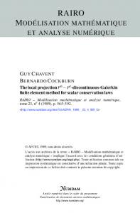
0.08 0.07 0.06 0.05 0,04 O9 ._> 0.03 0.02 0.01 0.00 0.00
/,"A'V,
.E
",:,,,,,
:
0
-- 1 000 - 2 000
$
- 3 000
..- . . . . . . . . . . . . . . ,-,'" J
. . . . . . . . .
- - C G New.k, strr DG Nr prr162 -
-
-
- 4 000 0
20
I0
30
40
50
60
,
C G _ N c w A m ~
-
D O _ D C V D
,
0.04
-
,
0.08
,
0.12
0.16
time/s
X / nl
(d)
,
- - -
CGFEM at t = 0.14s
(c) T h e v a r i a t i o n of effective plastic
Fig.3 T h e p r o p a g a t i o n of c o m p r e s s i o n waves in t h e s a t u r a t e d p o r o - e l a s t o - p l a s t i c colu m n in a d r a i n e d c o n d i t i o n . Comparisons of t h e effective stress a n d t h e p o r e pressure wave s h a p e s a m o n g D G A ) C V D , DG_DDVD, CGFEM (continued)
s t r a i n o c c u r r i n g a t t h e free e n d of the column with respect to time
Fig.4 T h e effective p l a s t i c s t r a i n s in t h e s a t u r a t e d p o r o - e l a s t o - p l a s t i c colu m n in a d r a i n e d c o n d i t i o n
m a t e r i a l is a s s u m e d e l a s t i c w i t h E = 1.0 x 10⁵ k P a , p~ =
2000kg/m
for t h e
3, v =
solid phase
0.3, K s
pl
and
1 x 10 . 6 m / s , K / =
=
=
6.146 x 10⁵kPa
1 0 0 0 k g / m a, k ~
=
2.0 x 10⁴ k P a for t h e f l u i d p h a s e .
T h e p o r o s i t y is n = 0.322.
45 ~
F i g u r e s 6 ~, 8 s h o w t h e
0.07 0.06
O
0.05
j
~9
0.04 Q. ~9 >
f
S'
0.03 0.02 0.01
- ---
Da_DCVD DO_DDVD
.....
CO_Newma~
f
Ic
--
10m
*1
0.00 0
10
20
30
40
50
60
X / nl
(a) T h e
d i s t r i b u t i o n along t h e s a t u -
rated elasto-plastic column at time t = 0.06 s
0.07 c
.,.5" ?
0.04 > ~o ~9
0.02
70 kN
,~
0.05
0.03
P
9~.
0.06
Q.
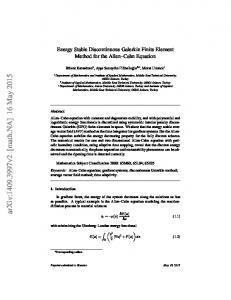
(a) G e o m e t r y , finite e l e m e n t m e s h a n d t h e applied load
/" /" r........
0.01
/ ."
[/
t=O.O05 s (b) T h e load h i s t o r y
--D~ - - - Da DcvD DDVD ..... co Nc~wrk
qJ
0.00 0
10
20
30
40
t
50
X/nl
(b) T h e d i s t r i b u t i o n along t h e s a t u rated elasto-plastic column at time t = 0.14s
60
Fig.5 S c h e m a t i c s t a t e m e n t of t h e twod i m e n s i o n a l s t r e s s wave p r o b l e m in a saturated poro-elastic medium : a s q u a r e p a n e l in t h e p l a n e s t r a i n s u b j e c t e d to a n i n c l i n e d i m p u l s e c o m p r e s s i o n load a t t h e t o p left corner
73
74
ACTA MECHANICA SINICA
(a) The present DGA:)CVD
method
(b) T h e C G F E M using the N e w m a r k m e t h o d Fig.6 T h e pore pressure distributions in t h e square panel of a s a t u r a t e d poro-elastic m e d i a at t = 0.025 s
(a) T h e present D G _ D C V D m e t h o d
(b) T h e C G F E M using t h e N e w m a r k m e t h o d Fig.7 T h e sphere stress distributions in the square panel of a s a t u r a t e d poro-elastic m e d i u m at t = 0.025 s
2004
(a) T h e present D G _ D C V D m e t h o d
(b) T h e C G F E M using the N e w m a r k m e t h o d Fig.8 T h e shear stress distributions in the square panel of a s a t u r a t e d poroelastic m e d i u m at t = 0.025 s
numerical results for the pore fluid pressure, the mean stress and the shear stress distributions within the domain at time t -- 0.025 s obtained by the proposed DG_DCVD method and the CG_Newmark method using the time step At = 1 x 10 -3 s. It is noted that the displacements of both the solid and the fluid phases at the left and the top boundaries of the square domain are free. Along with the P-wave propagation within the domain, there are the S-wave propagation within the domain and Rayleigh wave travelling along the free boundaries. The intersections of the P-wave with the free boundaries form propagating point disturbances with the P-wave speed, which generate the Head wave on the S-wave front travelling behind the P-wave propagation. The interactions among P-wave, S-wave and Rayleigh wave make the wave form within the domain rather complicated. Nevertheless, the silent nature at the neighborhood of point A, where the impulse load is applied, in the present example should be recovered with travelling waves going ahead due to the characteristic of an impulse load. Figures 6~8 demonstrate the good performance of the proposed DG_DCVD method in reproducing the silent nature at the zone near the place where the impulse load is applied, as the resulting travelling waves go ahead, while the CG_Newmark method fails to do so.
Vol.20, No.1 5
Li XK & Yao DM: Time Discontinuous FEM for Dynamics in Porous Medium Subgrade
CONCLUSIONS
AND DISCUSSSIONS
(1) The traditional Galerkin finite element method characterized by the semi-discrete procedure in the spatial domain combined with finite difference methods such as the Newmark method in the time domain fails to capture discontinuities or sharp gradients of the solution for the dynamic problems subjected to impulse loads with propagating waves where the stress normal to the surface of its wave front is discontinuous across it. In addition, it is also incapable of filtering out the spurious high frequency modes and controlling the spurious numerical oscillation. (2) The essential features of discontinuous Galerkin finite element methods are to use finite element discretizations in both space and time simultaneously and to permit the assumed unknown vectors and their derivatives with respect to time to be discontinuous at the discrete time levels. It can effectively capture the discontinuities across the wave front and filter out the spurious high frequency modes and control the spurious numerical oscillation. (3) As compared with the existing DG finite element formulations, in which a piecewise linear interpolation approximation is used for the discretization of displacements and velocities in the time domain, the proposed DG finite element formulations are characterized by a specific P3-P1 interpolation approximation, which uses piecewise cubic and linear interpolations for both displacements and velocities in the time domain, respectively. Consequently, the continuity of the displacement vector at each discrete time instant is automatically ensured, whereas the discontinuity of the velocity vector at the discrete time levels still remains. The computational cost is then obviously reduced,
75
particularly for the material non-linear problems.
REFERENCES 1 Hughes T JR, Hulbert GM. Space-time finite element methods for elastodynamics: Formulations and error estimates. Comput Methods Appl Mech Eng, 1988, 66: 339~363 2 Hulbert GM, Hughes T JR. Space-time finite element methods for second-order hyperbolic equations. Cornput Methods Appl Mech Eng, 1990, 84:327~348 3 Hulbert GM, Time finite element methods for structural dynamics. Int J Numer Methods Eng, 1992, 33: 307~331 4 Johnson C. Discontinuous Galerkin finite element methods for second order hyperbolic problems. Computer Methods Appl Mech Eng, 1993, 107:117~129 5 Li XD, Wiberg NE. Structural dynamic analysis by a time-discontinuous Galerkin finite element method. Int Y Numer Methods Eng, i996, 39:2131,-~2152 6 Li XD, Wiberg NE. Implementation and adaptivity of a space-time finite element method for structural dynamics. Comput Methods Appl Mech Eng, 1998, 156: 211~229 7 Wiberg NE, Li XD. Adaptive finite element procedures for linear and non-linear dynamics. Int J Numer Methods Eng, 1999, 46:1781~1802 8 Durate A, Carmo E, Rochinha F. Consistent discontinuous finite elements in elastodynamics. Comput Methods AppI Meeh En9, 2000, 190:193~223 9 Freund J. The space-continuous-discontinuous Galerkin method. Comput Methods Appl Mech Eng, 2001, 190:3461~3473 10 Zienkiewicz OC, Shiomi T. Dynamic behaviour of saturated porous medium; The generalized Blot formulation and its numerical solution. Int J for Numer and Anal Methods in Geomechanics, 1984, 8:71~96 11 Duxbury PG, Li XK. Development of elasto-plastic material models in a natural coordinate system. Cornput Methods Appl Mech Eng, 1996, 135:283~306