May 15, 2001 - We demonstrate the reconstruction of one- and two-dimensional objects by numerically backpropagating mea- sured scattered ... far-field position P0 can be mathematically time re- ... A col- limated input field diffracts in all directions from an object. .... THz plane wave that best approximated the spatiotem-.
May 15, 2001 / Vol. 26, No. 10 / OPTICS LETTERS
681
Time reversal and object reconstruction with single-cycle pulses A. Boh Ruffin, Joan Decker, Laurent Sanchez-Palencia, Lénaic Le Hors, John F. Whitaker, and Theodore B. Norris Center for Ultrafast Optical Science, University of Michigan, 1006 IST Building, 2200 Bonisteel Boulevard, Ann Arbor, Michigan 48109-2099
J. V. Rudd Picometrix, Inc., P.O. Box 130243, Ann Arbor, Michigan 48113-0243 Received October 10, 2000 We demonstrate the reconstruction of one- and two-dimensional objects by numerically backpropagating measured scattered terahertz transients. The spatial resolution determined by the Sparrow criterion is found to correspond to approximately 30% of the peak wavelength and 85% of the mean wavelength of the power spectrum of the single-cycle waveform. © 2001 Optical Society of America OCIS codes: 050.1960, 100.3190.
An important class of inverse problem in optics is imaging, or object reconstruction. It is well known that object reconstruction can be accomplished if the phase as well as the amplitude distribution of the f ield scattered by the object is measured. In diffraction or imaging problems, one typically considers the scattering of a narrow-band field; in this Letter we consider the scattering of extremely broadband, single-cycle fields and demonstrate a new method for object reconstruction based on time reversal. This study has been facilitated by recent advances in single-cycle terahertz (THz) pulse generation and measurement and builds on recent investigations of the scattering of THz pulses1 – 3 and on developments in direct THz imaging.4 In this spirit, it is also our expectation that this study can serve as a scale model for time-reversal imaging with single-cycle pulses in other systems. Our approach is based on the time-reversal symmetry of Maxwell’s equations and the Huygens– Fresnel diffraction theory.5 The diffraction of broadband electromagnetic pulses can be treated with the timedomain Huygens – Fresnel diffraction formula6 ∂ ZZ cos u ≠ µ r01 ds , (1) u共P0 , t兲 苷 u P1 , t 2 c S 2pcr01 ≠t where u is the zenith angle made with respect to the optic axis, c is the speed of light, and r01 is the distance from object point P1 to far-field point P0 . This integral calculates a diffracted f ield u共P0 , t兲 from any given input f ield u共P1 , t 2 r01 兾c兲, where ds is an area element in the aperture E. Because of the time-reversal symmetry of Maxwell’s equations, the diffracted f ield at far-f ield position P0 can be mathematically time reversed and then used as an input f ield in the above integral equation to reconstruct the f ield at the object’s position P1 . That is, it is possible to determine the (spatial) transmission function at object P1 by taking a THz waveform measured at several off-axis positions P0 and applying a backpropagation algorithm to these fields. Because the time-domain THz measurement yields directly the electric field amplitude, these scattered waveforms contain all the phase (time 0146-9592/01/100681-03$15.00/0
delay) information that one needs to obtain the spatial distribution of the electric f ield across the object. Intuitively, each temporal feature of the scattered waveform corresponds to the arrival of an impulse from a different region of the object. The backpropagation algorithm simply numerically differentiates the measured diffracted transient, computes the time-reversed field u共P0 , t 1 r01 兾c兲, and uses the result as an input to the time-reversed Kirchhoff diffraction integral. In our experiments the scattered fields are measured at several angles on a sphere (referred to as the intermediate screen) centered on the object. It should be noted that the boundary conditions that yield Eq. (1) are for a planar aperture; for a curved surface (at the intermediate screen), proper inclusion of the boundary condition leads to a modif ication of the obliquity factor. Thus the f ield in the object plane is given by 1 ZZ 共1 1 cos u兲 u共P1 , t兲 苷 2 4pc S0 ∂ µ ≠ r01 ds 0 , 3 (2) u P0 , t 1 ≠t c where u共P0 , t 1 r01 兾c兲 is the time-reversed scattered THz field in the intermediate screen and ds 0 is an area element in the intermediate screen. In our f irst experiments we demonstrated the concept of time-reversal imaging by using a one-dimensional object. A collimated, single-cycle THz pulse with a beam diameter of approximately 3.0 cm was incident on a 14-slit grating formed by aluminum-foil strips on a low-density polyethylene substrate with a periodicity, albeit irregular, of approximately 2 mm. The grating diffracted the pulse in a plane perpendicular to the grating axis, as illustrated schematically in Fig. 1. The diffracted THz f ields were measured at 62 zenith positions 共0± # u # 45±兲 at a radial distance of 25 cm centered on the object. To maintain the time-zero reference for all off-axis positions, we used a commercial THz measurement system in which femtosecond optical pulses were delivered to the emitter and detector photoconductive antennas via single-mode optical fiber.7 With the © 2001 Optical Society of America
682
OPTICS LETTERS / Vol. 26, No. 10 / May 15, 2001
for only one zenith angle u because, as the object is rotated through 0 # f # 2p, there is access to all spatial frequencies that correspond to 2ud # u # ud for both the x and y directions in the object plane. Acquiring data for only one zenith angle permitted the use of a conventional photoconductive free-space THz system. For the 2-D experiments this system had a peak and a
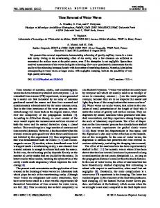
Fig. 1. One-dimensional (1-D) experimental setup. A collimated input f ield diffracts in all directions from an object. (The input field shown represents a field measured in the near field of the THz emitter.) These scattered transients are then recorded at different azimuths along the intermediate (detection) screen. For the numerical backpropagation, the positions at the intermediate screen are locations for virtual sources, u共P0 , t 1 r01 兾n兲, that will propagate in the reverse direction to the object plane.
exception of the f iber coupling of the antennas, the system operates in the same manner as a conventional time-domain THz system.8 Both emitter and receiver used a 90± bow-tie antenna fabricated upon lowtemperature-grown GaAs and were coupled to silicon aplanatic hyperhemispherical substrate lenses with a radius of 4 mm. This photoconductive THz system had a mean frequency of 288 GHz with a FWHM of 350 GHz and usable frequency components up to 1.0 THz. In Fig. 2(a) we show the scattered THz transients measured at each zenith position on the intermediate screen. For increasing nonzero angles one can observe the linear increase in the wave-form period that corresponds to the later arrival times of the f ields from slits at an increased separation from the detector. We reconstructed the object by using the time-reversed data of Fig. 2(a) as the input f ield u共P0 , t 1 r01 兾c兲 in Eq. (2) and then plotting the electric field versus lateral position in the object plane. The result is shown in Fig. 2(b); the grating periodicity is clearly resolved, although the edge resolution is limited by the system bandwidth. From the edge response, determined by convolution of the grating dimensions with a Gaussian point-spread function, we found the spatial resolution of the system to be approximately 350 mm. We next demonstrate the principle of time-reversal imaging with a two-dimensional (2-D) object. Ideally, in the 2-D case the scattered fields should be measured at points on a spherical grid that extend over the intermediate screen in both zenith 共u兲 and azimuthal 共f兲 directions, but doing so is experimentally diff icult. Instead, we f ixed the detector at a single angle u 苷 ud fi 0 and rotated the object about the z axis from 0 to 2p, as shown in Fig. 3. Rotation in f of the object is entirely equivalent to rotation of the detector on the sphere in a circle u 苷 ud , 0 # f # 2p. Intuitively, it is clear that it is suff icient to acquire data
Fig. 2. One-dimensional experimental results: (a) the diffracted f ields at the intermediate screen. These waveforms were used as input sources in Eq. (2) to reproduce the transmission function of the object (Fig. 1, inset); the result is shown in (b).
Fig. 3. 2-D experimental setup. Diffracted electric f ields are measured at one off-axis position ud 苷 12± as the object (spiral) is rotated about the z axis from 0 to 2 p. This figure also demonstrates how measuring at one off-axis position while rotating the object is equivalent to measuring the fields on a spherical screen.
May 15, 2001 / Vol. 26, No. 10 / OPTICS LETTERS
Fig. 4. (a) Time-reversal imaging simulation. Here the scattered field distribution of the electric field incident upon the object was calculated with Eq. (1). The field was then time reversed and backpropagated by use of Eq. (2) under the same conditions as in the experiment. (b) Image obtained from the experimental data after the backpropagation algorithm described in the text has been performed.
Fig. 5. Two electric field measurements at the intermediate screen for the f 苷 0± and f 苷 15± orientations. From delay between the waveforms and Eq. (3), the spatial resolution was determined to be 674 mm.
mean frequency of 136 and 377 GHz, respectively, with a FWHM of 351 GHz. For the results shown here, the diffracted f ields were measured at one zenith position, ud 苷 12±, and 72 azimuthal 共f兲 positions from 0 to 2p. To test the principle of 2-D time-reversal imaging by using the scheme described above, we first carried out a simulation, numerically propagating a single-cycle THz plane wave that best approximated the spatiotemporal prof ile of the actual beam onto a binary aperture identical to the one shown in Fig. 3. Using Eq. (1), we first calculated the diffracted field with parameters identical to those in the experimental arrangement for the object oriented at f 苷 0±, 5±, 10± . . . 360± at a radial distance of 15 cm and at the zenith position ud 苷 12±. The time-reversal image was then calculated with Eq. (2) and is shown in Fig. 4(a); the object is clearly imaged and corroborates the principle of f scanning for reconstruction of the object. An experimental demonstration of the principle that used the same parameters was implemented with an amplitude-contrast object similar to the one represented in Fig. 3 (a gold spiral antenna structure fabricated upon fused silica). The backpropagation result is shown in Fig. 4(b); the opaque and clear portions of the aperture are clearly resolved. It is
683
interesting to consider the question of spatial resolution for this 2D time-domain imaging scheme. Our approach is to def ine the resolution by using a time-domain adaptation of the Sparrow criterion. First, consider two temporal wave-form measurements at the intermediate screen as one normally would two spatial point-spread functions. According to the Sparrow criterion,9 two pulses separated by Dt are resolved if there is a clear local minimum between the principal peaks of the two waveforms. If two object points separated by Dx give rise to waveforms separated by at least Dt at u 苷 ud , then they will be resolved. By simple geometry, Dx 苷 cDt兾sin ud .
(3)
In our 2-D experiment, by this criterion the temporal resolution was 467 fs; thus we found that waveforms taken for orientations separated by Df $ 15± are resolved, as illustrated in Fig. 5. For a detector position ud 苷 12± this value of Dx corresponds to a spatial resolution of 674 mm. Intuitively, one might expect the spatial resolution for imaging with single-cycle pulses to be approximated between the wavelengths at which the power spectrum peaks and its centroid; for our system those wavelengths are lpeak 苷 2.2 mm and lmean 苷 796 mm, respectively. Thus the actual spatial resolution obtained by the time-reversal imaging technique is approximately 30% of the peak wavelength and 85% of the mean wavelength of the single-cycle pulses used in this experiment. This study was partially supported by the National Science Foundation through the Center for Ultrafast Optical Science under grant STC PHY 8920108, in addition to provisions from the U.S. Air Force Off ice of Scientific Research under grant F49620-98-1-0365. A. B. Ruff in acknowledges support through the National Physical Science Consortium Fellowship. J. V. Rudd acknowledges the support of the U.S. Air Force Small Business Innovation Research Initiative, contract F33615-98-C-2820. References 1. J. Bromage, S. Radic, G. Agrawal, C. R. Stroud, P. M. Fauchet, and R. Sobolewski, J. Opt. Soc. Am. B 15, 1399 (1998). 2. E. Budiarto, N.-W. Pu, S. Jeong, and J. Bokor, Opt. Lett. 23, 213 (1998). 3. R. A. Cheville and D. Grischkowsky, Appl. Phys. Lett. 67, 1960 (1995). 4. D. M. Mittleman, M. Gupta, R. Neelamani, R. G. Baraniuk, J. V. Rudd, and M. Koch, Appl. Phys. B 68, 1085 (1999). 5. M. Born and E. Wolf, Principles of Optics (Cambridge U. Press, Cambridge, 1997). 6. J. W. Goodman, Introduction to Fourier Optics (McGraw-Hill, New York, 1996). 7. J. V. Rudd, D. Zimdars, and M. Warmuth, Proc. SPIE 3934, 27 (2000). 8. M. van Exter and D. Grischkowsky, IEEE Trans. Microwave Theory Tech. 38, 1684 (1990). 9. R. Guenther, Modern Optics (Wiley, New York, 1990).