algorithm performs tensor decomposition using a hierarchical approach that ...... out of the 80 images, 60 of them (30 for each subject) are used to train the.
Title
Author(s)
Citation
Issued Date
URL
Rights
Non-negative matrix and tensor factorization with applications to feature extraction
Ang, Man Shun; 洪万順 Ang, M. S. [洪万順]. (2016). Non-negative matrix and tensor factorization with applications to feature extraction. (Thesis). University of Hong Kong, Pokfulam, Hong Kong SAR. 2016
http://hdl.handle.net/10722/238838
Creative Commons: Attribution-NonCommerical 3.0 Hong Kong License
Abstract of the Dissertation Entitled
Non-negative Matrix and Tensor Factorization with Applications to Feature Extraction Submitted by
ANG Man Shun for the degree of Master of Philosophy at the University of Hong Kong in August 2016 Non-negative big data arising in many engineering problems may take the form of matrices or multi-dimensional array called tensors. To preserve the nonnegativity property for interpretability, these non-negative algebraic structures can only be analyzed by means of Non-negative Matrix Factorization (NMF) and Non-negative Tensor Factorization (NTF) techniques, which have attracted increasing attention in the field of signal processing and machine learning. The NMF and NTF problem is to decompose a non-negative array into a lower dimensional rank structure so that the components of the decomposition characterize the essential features of the data. This thesis investigates the matrix and tensor modeling of non-negative data with an aim to develop efficient algorithms for NMF and NTF, and subsequently their applications for feature extraction. Two new methods, called the Double Non-negative Least Squares (DNNLS) and Separable Non-negative Tensor Factorization (SNTF), are developed for NMF and NTF, respectively. The proposed SNTF algorithm is then used to develop a general methodology for extracting features from non-negative multiclass data for the purpose of classification. Many existing NMF algorithms produce decomposition solutions that are inconsistent due to unpredictable convergence to local minima. By viewing the
data matrix V as a collection of data points in the non-negative space, the associated non-negative geometry provides a way for interpreting the NMF problem as a generator extraction problem followed by non-negative regression. The proposed D-NNLS method performs NMF V=WH by extracting the extreme points from the original data cloud of V using non-negative least squares (NNLS) to construct W. The corresponding coefficient matrix H is then obtained by NNLS again such that V=WH. After comparing five commonly used NNLS algorithms, experimental results show that the Block Principal Pivoting method is the best NNLS algorithm for the proposed D-NNLS NMF. A data tensor can be treated as the multi-linear extension of the non-negative matrix obtained by stacking multiple matrices together. The proposed SNTF algorithm performs tensor decomposition using a hierarchical approach that sequentially unfolds the tensor along different directions to produce matrices, and then applies the proposed D-NNLS NMF algorithm to the matrices to extract features along different directions of the original data tensor. Based on the proposed SNTF, a feature extraction methodology is developed whereby non-negative multiclass data represented as a third-odder tensor is first decomposed into a CP (CANDECOMP and PARAFAC) model consisting of characteristic components whose weightings serve as features. The use of the methodology is demonstrated by means of applications to Electrooculography signal processing and face image classification problems. The effectiveness of all the proposed methods is evaluated using both synthetic and real data from biomedical signal processing and image analysis domains. Experimental results show that the proposed methods are promising in terms of computational error, computational time requirement and classification accuracy.
Non-negative Matrix and Tensor Factorization with Applications to Feature Extraction by Ang Man Shun B. Eng. H.K.
A thesis submitted in partial fulfillment of the requirements for the Degree of Master of Philosophy at the University of Hong Kong August 2016
[This page is intentionally left blank]
Declaration I declare that this thesis, submitted in partial fulfilment of the requirements for the degree of Master of Philosophy and entitled “Non-negative Matrix and Tensor Factorization with Application to Feature Extraction” and the research work thereof represents my own work, except where due acknowledgement is made, and that it has not been previously included in a thesis, dissertation or report submitted to this University or to any other institution for a degree, diploma or other qualifications.
Signed ………………………………………… ANG Man Shun August 2016
i
Acknowledgement I would like to thank my supervisor Prof. Y. S. Hung, for the patience and support on my research work during the past 2+ years since I was lucky enough to be his Undergraduate Final Year Project student. This M.Phil. thesis could not have been possible without his advice and guidance. I would also like to thank my co-supervisor, Dr. Z.G. Zhang, for his helpful suggestions on my work. His suggestions were always insightful and helped me a lot to become a better researcher. Special thanks go to Prof. Ricky Y. K. Kwok, Dr. B. Zhang, Dr. H. F. Tam, Dr. Y. Tu, Mr. A. Tan, Dr. Z. Fu and Mr. Thomas Kwan for their useful comments during my study in HKU EEE. Last but not least, I would like to thank my mum for her support and understanding.
ii
Table of Contents Declaration ……………………………………………………………………i Acknowledgement …………………………………………………………...ii Table of Contents ……………………………………………………………iii Symbols ………………………………………………………………………v Abbreviations and Acronyms …………………………………………….....vii List of Tables ……………………………………………………………….viii List of Algorithms ……………………………………………………………ix List of Figures ………………………………………………………………...x Chapter 1 Introduction and Preliminaries .................................................... 1 1.1 The early development of NMF ........................................................................ 1 1.2 The current state-of-the-art in NMF .................................................................. 3 1.3 The future of NMF - NTF ................................................................................. 4 1.4 The contributions of this thesis ......................................................................... 5 1.5 Thesis organization .......................................................................................... 7 Chapter 2 Non-negative Matrix Factorization .............................................. 8 2.1 Review of Convex Geometry............................................................................ 8 2.2 Non-negative Matrix Factorizations................................................................ 11 2.2.1 NMF Algorithm ...................................................................................... 11 2.2.2 SNMF ..................................................................................................... 15 2.3 SNMF Algorithms .......................................................................................... 17 2.3.1 The Double Non-Negative Least Squares ................................................ 17 2.3.2. The Non-Negative Least Squares............................................................ 21 2.4 Experiments ................................................................................................... 27 2.4.1. Data and notations .................................................................................. 27 2.4.2. NPM should be rejected ......................................................................... 28 2.4.3. MMM is slow ......................................................................................... 29 2.4.4. BPM is the best method for D-NNLS ..................................................... 30 2.4.5. BPM based D-NNLS SNMF versus SNPA ............................................. 31 iii
Chapter 3 Non-negative Tensor Factorization ............................................ 34 3.1 Tensor Fundamentals ..................................................................................... 34 3.1.1 Tensor as a multidimensional array. ........................................................ 34 3.1.2 Types of tensors ...................................................................................... 36 3.1.3 Tensor algebra ......................................................................................... 38 3.1.4 Comparison of tensor modelling to matrix modelling .............................. 42 3.1.5 Tensor Models ........................................................................................ 44 3.2 SNTF ............................................................................................................. 48 3.2.1 A special case for order-3 tensor.............................................................. 49 3.2.2 SNTF algorithm for general order-N tensor ............................................. 52 3.3 Experiments ................................................................................................... 53 3.3.1. Performance of SNTF on electrooculography data .................................. 53 Chapter 4 Applications .................................................................................. 56 4.1. Feature Extraction by SNTF – General Description ....................................... 56 4.2. Feature Extraction for Electrooculography Signals ........................................ 61 4.3. Feature Extraction for Face Images Classification ......................................... 64 Chapter 5 Conclusions ................................................................................... 69 5.1. Summary of the thesis ................................................................................... 69 5.2. Application of SNTF on mining dynamic behavior of a signal ....................... 69 References ....................................................................................................... 71
iv
Symbols Scalar variables and indices are denoted by lower-case italic font such as x, y, z, i, j, k. Vectors are denoted by lower-case bolded font such as x, z, both italic and non-italic. Capitalized font represents set such as A, V. Capitalized bolded font denotes matrix such as A, V, X. Tensors are denoted by capitalized bolded font with underline or calligraphic font such as X and 𝒵. A mathematical object (scalar, vector, matrix and tensor) A is nonnegative is denoted by 𝐀 ≥ 0, 𝐴𝑖𝑗 ≥ 0 or 𝐀 ∈ ℝ+ . Unless stated otherwise, the symbol n always refers to the number of data points of a set V or the number of columns in a matrix V. The symbol p always refers to the dimension of the data point of V or the dimension of the column vector of the matrix V. Symbol ℝ
Meaning Set of real numbers.
ℝ+
Set of non-negative real numbers.
ℝ𝐼
Set of real-valued 𝐼-dimensional vectors.
ℝ𝐼×𝐽
Set of real-valued (𝐼 × 𝐽)-dimensional matrices.
ℝ𝐼×𝐽×𝐾
Set of real-valued (𝐼 × 𝐽 × 𝐾)-dimensional order-3 tensors.
ℝ𝐼1 ×…𝐼𝑘
Set of real-valued (𝐼1 × … × 𝐼𝑘 )-dimensional order-k tensors.
𝐕T
Transpose of matrix V.
𝐕 −1
Inverse of matrix V.
𝐕†
Moore-Penrose pseudo-inverse of matrix V.
‖𝐕‖𝝃
Matrix norm, or divergence measure specified by 𝜉.
‖𝐕‖𝐹
Fresenius norm of matrix V.
𝐕 ∈ ℝ𝑝×𝑛 +
Matrix A of size p-by-n.
[𝐕]𝑖𝑗
The ith-row jth-column element of matrix V.
𝐕:𝑗
The jth-column of matrix V.
𝐕𝑖:
The ith-row of matrix V.
v
𝐕:𝐵
The sub-matrix formed by the indexed column of matrix V by the index set B.
𝑒, 𝒆, 𝐄, 𝐄
Residue scalar, vector, matrix and tensor.
𝐈𝑟×𝑟
Identity matrix.
𝐈𝑟×𝑟×𝑟
Super Identity order-3 tensor.
𝐗 (𝜇) , 𝐗 (𝜇)
Mode- matricized tensor X.
𝐗 𝑖𝑗𝑘
(𝑖, 𝑗, 𝑘)-th element of order-3 tensor X.
𝐗 𝑖𝑗:
(𝑖, 𝑗)-th mode-3 fiber of order-3 tensor X.
𝐗 𝑖:𝑘
(𝑖, 𝑘)-th mode-2 fiber of order-3 tensor X.
𝐗 :𝑗𝑘
(𝑗, 𝑘)-th mode-1 fiber of order-3 tensor X.
𝐗 𝑖::
𝑖-th horizontal slice of order-3 tensor X.
𝐗 :𝑗:
𝑗-th vertical slice of order-3 tensor X.
𝐗 ∷𝑘
𝑘-th frontal slice of order-3 tensor X.
𝐀⨂𝐁
Hadamard element-wise multiplication of matrix A and B.
𝒂⨂𝒃
Vector-vector outer product, depends on the context.
𝐀⊘𝐁
Hadamard element-wise division of matrix A and B.
𝒯 ×𝜇 𝐀
Mode- tensor-matrix multiplication between tensor 𝒯 and matrix A.
𝒯 ×𝜇 𝒂
Mode- tensor-matrix contraction multiplication between tensor 𝒯 and vector a.
diag(a)
Diagonal matrix formed by the element in a.
vec
Vectorization.
mat
Matricization.
ten
Tensorization.
⟦𝐀, 𝐁, 𝐂⟧
Kruskal operation on matrices A, B and C.
vi
Abbreviations and Acronyms The following abbreviations and acronyms will be used in the whole thesis. The full name of the abbreviation/acronyms will be shown when the terms first appear in the thesis. Abbreviations Meaning ALS
Alternating Least Squares
CP
CANDECOMP / PARAFAC
CSS
Colum Subset Selection
KKT
Karush-Kuhn-Tucker conditions
LFP
Linear Feasible Problem
LS
Least Squares
NMF
Non-negative Matrix Factorization
NTF
Non-negative Tensor Factorization
PARAFAC
Parallel Factor Analysis
PCA
Principal Component Analysis
RPE
Relative Percentage Error
SNPA
Successive Non-negative Projection Algorithm
SNMF
Separable Non-negative Matrix Factorization
SPA
Successive Projection Algorithm
SVD
Singular Value Decomposition
vii
List of Tables Table 2-1. Common choices of measures for NMF. .................................................... 12 Table 2-2. Common constrained NMFs ...................................................................... 13 Table 2-3 Images configurations ................................................................................. 27 Table 2-4. Computational results of SNMFs. .............................................................. 33
viii
List of Algorithms Algorithm 2-1. NMF by MU [Lee99].......................................................................... 14 Algorithm 2-2. NMF by ALS...................................................................................... 15 Algorithm 2-3. SNMF Solution Framework ................................................................ 16 Algorithm 2-4. LPS Framework .................................................................................. 18 Algorithm 2-5. D-NNLS ............................................................................................. 20 Algorithm 2-6. Successive Projection NMF [Gillis14] ................................................ 21 Algorithm 2-7. NNLS by ASM [Lawson74]. .............................................................. 22 Algorithm 2-8. NNLS by BPM [Park11] ..................................................................... 23 Algorithm 2-9. NNLS by FGM [Gillis14] ................................................................... 25 Algorithm 2-10. NNLS by MMM [Hunter04] ............................................................. 26 Algorithm 3-1. SNTF for order-3 tensor...................................................................... 49 Algorithm 3-2. SNTF for order-N tensor. .................................................................... 52 Algorithm 4-1. SNTF Feature Extraction with CP-model. ........................................... 60
ix
List of Figures Figure 1-1. Examples of non-negative matrices: spectrogram and images. .................... 2 Figure 1-2. A face image .............................................................................................. 2 Figure 1-3. Decomposing a spectrum using pre-defined non-negative Gaussian bases. . 2 Figure 1-4. The decomposition of an order-3 tensor into three components tensors. ...... 5 Figure 2-1. A two dimensional cone with two generators. ............................................. 9 Figure 2-2. A three dimensional cone with six generators. .......................................... 10 Figure 2-3. A non-convex cone having two “sub-cones” pointing in two directions. ... 10 Figure 2-4. Illustration of NMF in the vector form. ..................................................... 11 Figure 2-5. Image of cameraman, women, autumn, clown and moon. ......................... 27 Figure 2-6. RPE of different methods applied to clown image across different rank. ... 28 Figure 2-7. RPE of different methods applied to woman and cameraman image for across different rank. ............................................................................................................. 29 Figure 2-8. Computation time of different method applied to woman data for different decomposition rank. (y-axis of left figue: linear; right figure: log-scale-). ................... 30 Figure 2-9. RPE of different methods applied to the face imaged across rank. ............. 30 Figure 2-10. Computational time of different methods applied to the face imaged across rank. ........................................................................................................................... 31 Figure 2-11. RPE vs computational time of face image. .............................................. 31 Figure 2-12. RPE of D-NNLS and SNPA. .................................................................. 32 Figure 2-13 . Computational Time of D-NNLS and SNPA. ......................................... 33 Figure 3-1. Scalar, vector, matrix and 3-dimensional tensor. ....................................... 35 Figure 3-2. Fibers of an order-3 tensor. Picture modified from [Cichocki09]. .............. 35 Figure 3-3. Slices from tensor. Picture modified from [Cichocki09]. ........................... 36 Figure 3-4. Examples of data tensor. Picture from [Hu14], MATLAB and [Gillis14]. . 37 Figure 3-5. The EOG tensor. ....................................................................................... 37 Figure 3-6. A bi-spectrum of EEG. ............................................................................. 38 Figure 3-7. Tensor-vector contraction product. Picture from [Cichocki09]. ................. 41 Figure 3-8. Simple tensor. ........................................................................................... 44 Figure 3-9. The CP model. .......................................................................................... 45 Figure 3-10. The Tucker Model. ................................................................................. 46 Figure 3-11. The Tucker3 model with dimension specified. ........................................ 47
x
Figure. 3-12. Kernels of different models. ................................................................... 48 Figure 3-13. Illustration of the first three steps in algorithm. ....................................... 50 Figure 3-14. Illustration of the tensor “division”. ........................................................ 50 Figure 3-15. Illustration of the last two steps in the algorithm. .................................... 51 Figure 3-16. The overall decomposition model of the proposed SNTF. ....................... 51 Figure 3-17. [Left] Slice plot of EOG tensor. [Right] Error plot of two NTF algorithms for different ranks. ...................................................................................................... 54 Figure 3-18. Computational time of two methods across rank. .................................... 55 Figure 3-19. Computational time (left: log scale; right: linear scale) of the two NTF methods across data size. ............................................................................................ 55 Figure 4-1 The data set V. ........................................................................................... 56 Figure 4-2 The data tensor V. ..................................................................................... 57 Figure 4-3. CP decomposition of the tensor V. ............................................................ 57 Figure 4-4. CP decomposition of a tensor V with r = 3................................................ 58 Figure 4-5. SNTF Feature Extraction and classification process. ................................. 61 Figure 4-6. Component tensors obtained from the EOG tensor. ................................... 62 Figure 4-7. Top views of the three tensors................................................................... 63 Figure 4-8. Distribution of the two groups of signals in the feature space corresponding to the two distinctive component tensors. .................................................................... 64 Figure 4-9. Face image recognition problem. Images come from the Yale Face Database B. ............................................................................................................................... 65 Figure 4-10. Eigenface feature extraction and classification process. .......................... 66 Figure 4-11. Face images of all the 38 subjects in the Yale database B. ....................... 66 Figure 4-12. Binary Classification accuracies between all the 38 subjects. .................. 67 Figure 4-13. Feature Space of the face images. ........................................................... 68 Figure 5-1 Short Time Double Fourier Transform of a signal. ..................................... 70
xi
Chapter 1 Introduction and Preliminaries This chapter introduces the background of the thesis. Section 1.1 provides a discussion of the early development of Non-negative Matrix Factorization (NMF), which introduces the NMF and the algorithms developed in the early era of NMF. Section 1.2 describes the current state-of-the-art NMF, which introduces the new NMF called the Separable NMF. In Section 1.3, Nonnegative Tensor Factorization (NTF) is introduced as an extension of NMF, and a review of some current NTF algorithms is given. This chapter ends with a summary of the Contributions (Section 1.4) and an outline of the Organization of the thesis (Section 1.5). This chapter serves as an introduction of the thesis with technical details kept to a minimum.
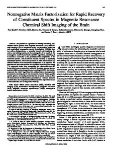
1.1 The early development of NMF The world is full of non-negative data. Figure 1-1 shows some non-negative matrices containing only non-negative data. For example, for the face image shown in Figure 1-2, each pixel represents a non-negative light intensity value. In the 3D visualization of the face image, all pixels have non-negative values along the z-axis representing intensity. A common practice in data modelling is to assume that the data has a lower dimensional linear structure, which may be revealed using matrix factorization methods. However, traditional approaches like Principal Component Analysis (PCA) and Singular Value Decomposition (SVD) are not suitable for nonnegative data because these methods may produce factors with un-interpretable negative entries. A decomposition method that produces non-negative factors should be used [Lee09].
1
Figure 1-1. Examples of non-negative matrices: spectrogram and images.
Figure 1-2. A face image
The very first paper on non-negative data decomposition came from the field of chemometrics on handling bases 𝒘𝑖 (blue curves in Figure 1-3) with nonnegative coefficients ℎ𝑖 . 𝒗 = 𝒘1 ℎ1 + ⋯ + 𝒘𝑟 ℎ𝑟 .
(1-1)
In this specific example, the spectrum 𝒗 in black is decomposed into blue basis 𝒘𝑖 ’s which are defined as prior Gaussian functions. That is, the structures of 𝒘𝑖 ’s in this example are pre-determined and not “learned” from data.
Figure 1-3. Decomposing a spectrum using pre-defined non-negative Gaussian bases. 2
Equation (1-2) is called Non-negative Vector Factorization (NVF). NVF was generalized to Non-Negative Matrix Factorization (NMF) by [Lee99], [Lee01]. The NMF problem. Given a non-negative matrix V, solve the following decomposition problem: 𝐕 = 𝐖𝐇 s. t. 𝐖 ≥ 𝟎 and 𝐇 ≥ 𝟎.
(1-2)
where the notation 𝐖 ≥ 𝟎 means that all the elements of W are non-negative. The reason why one has to apply NMF on decomposing non-negative data is the ability to extract sparse and more interpretable factors [Lee01],[Suyken14]. To solve the NMF problem, many algorithms (such as [Lee01], [Berry07], [Cichocki09], [Hoyer04] and [Hyvonen08]) have been proposed. Some of these algorithms, particularly those before year 2012, are poor because of two reasons: (i) they produce inconsistent, non-unique solutions, (ii) the formulation of equation (1-2) is over-relaxed and it is indeed NP-Hard [Vavasis09]. In the development of NMF, 2012 is the turning point after two important papers [Arora12] and [Bittorf12] were published. As a result of these two papers, NMF research before year 2012 may be referred to as “the early era of NMF”. We will discuss in Chapter 2 Section 2.2.1 the details of these NMF algorithms.
1.2 The current state-of-the-art in NMF The two papers in 2012 together with the papers [Donoho03] and [Laurberg08] worked on the problematic formulation of equation (1-2). These papers suggested the following new formulation called the Separable NMF (SNMF). The SNMF problem. Given a non-negative matrix V, solve the following decomposition problem: 𝐕 = 𝐖𝐇 s. t. 𝐖 ≥ 𝟎, 𝐇 ≥ 𝟎 and 𝐖 = 𝐕:𝐴 .
(1-3)
Equation (1-3) differs from equation (1-2) in the additional constraint 𝐖 = 𝐕:𝐴 stating that columns of W has to be chosen from certain columns of V specified 3
by the index set A. It is this additional constraint that turns the NP-Hard NMF problem into a tractable, solvable problem. In this sense, the SNMF formulation equation (1-3) splits the original NMF formulation (1-2) into two sub-problems: (i) to construct 𝐖 as a subset of columns of V, and (ii) to construct H from V and W. The first sub-problem is an instance of the Column Subset Selection (CSS) problem, and the second sub-problem can be solved by the Non-negative Least Squares (NNLS).
1.3 The future of NMF - NTF As NMF is the matrix extension of NVF, further extension can be made beyond NMF. The higher order extension of matrix is called tensor, which is a multidimensional array. [Cichocki09] has summarised various Non-negative Tensor Factorization (NTF) problems, formulation and algorithms. NTF generalizes the idea of NMF from linear algebra-based array processing to the field of multidimensional array processing and multi-linear algebra. In other words, if NVF is for vector and NMF is for matrix, then NTF is for tensor. Unlike the NMF formulation, there are multiple possible NTF formulations based on the fact that there are many possibilities in defining a tensor model, which will be discussed in Chapter 3. For example, Figure 1-4 shows an order-3 tensor decomposed into the sum of 3 component tensors.
4
Figure 1-4. The decomposition of an order-3 tensor into three components tensors.
1.4 The contributions of this thesis Since NTF is an extension from NMF, therefore it inherits the problems of NMF. That is, NMF-based method produces inconsistent solutions. Currently there is no “tensor version” of the SNMF. One of the goal in this thesis is to bridge the gap between SNMF and NTF. Therefore, the principal contribution of this thesis is on the analysis and development of a new NTF algorithm framework called Separable NTF (SNTF). The proposed SNTF is an extension of SNMF toward tensors with flexible tensor model structures that can be adapted to different existing tensor models. Other contributions of this thesis are: (i)
the analysis and the development of a new SNMF algorithm called Double Non-negative Least Squares (D-NNLS) based on convex geometry. Compared with existing SNMF algorithm called
5
Successive Non-Negative Projection Algorithm (SNPA) by [Gillis14], the proposed D-NNLS algorithm has similar performance in approximation accuracies but requires less computational time. (ii)
computational comparisons of five existing NNLS algorithms. Since the proposed D-NNLS algorithm relies on NNLS, it is necessary to choose a NNLS algorithm to make sure that D-NNLS using the chosen NNLS algorithm will be the most reliable and computationally efficient. This thesis compared five common NNLS methods, namely: The Active Set Method (ASM) [Lawson74], the Block Principal Pivoting Method (BPM) [Park11], the Majorization-Minimization Method (MMM) [Hunter04], Fast Gradient Descent Method (FGM) [Gillis14] and the Non-Negative Projection Method (NPM) [Hyvonen08], [Berry07]. The results from computational experiments suggested that the NPM approach, which is commonly used in NMF, is not justified and should be rejected, whereas BPM is the best method for NNLS.
(iii)
the application of the proposed SNTF algorithms on feature extraction from biomedical signals and for binary face classification.
In summary, this thesis has made investigations with novel contributions in the following research areas: 1. Non-Negative Matrix Factorization and Separable Non-Negative Matrix Factorization. 2. Non-Negative Least Squares and Constrained Optimization. 3. Convex Analysis, Column Subset Selection, Generator Enumeration. 4. Non-Negative Tensor Factorization. 5. Feature Extraction.
6
1.5 Thesis organization There are 5 chapters in the thesis. Chapter 1. Introduction and Preliminaries briefly introduces the development of NMF, SNTF and the NTF, followed by the problem statement and a summary of the contributions of the thesis, ending with the thesis organization. Chapter 2. Non-negative Matrix Factorization starts with a review of convex geometry, followed by the analysis of NMF and SNMF. Then the chapter focuses on the analysis and development of a proposed new SNMF algorithm called Double Non-negative Least Squares (D-NNLS). This chapter ends with a discussion of the algorithmic details of NNLS and comparisons. Chapter 3. Non-negative Tensor Factorization starts with fundamentals of tensors such as tensor algebra and tensor models, followed by an extension of the idea of SNMF to NTF leading to the Separable NTF (SNTF) algorithm. The chapter ends with computational experiments for comparing SNTF with existing NTF algorithms. Chapter 4. Applications focuses on the application of proposed NTF algorithms for feature extraction. Two examples are provided to illustrate the use of NTF for feature extraction from biomedical signals and face images. The thesis ends with Chapter 5. Conclusions which provides a summary of the whole thesis and a brief discussion on further potential applications. Conference papers. The work described in this thesis has generated two publications in conferences as listed below: 1. A. M. S. Ang, and Y. S. Hung, “Non-negative Tensor Factorization and Application”, Advance Health Informatics, Gordon Research Conference, 2016, Hong Kong, July 2016 2. A. M. S. Ang, Y. S. Hung, and Z. G. Zhang, “A Non-negative Tensor Factorization Approach to Feature Extraction for Image Analysis”, 2016 IEEE International Conference on Digital Signal Processing, Beijing, China, October, 2016
7
Chapter 2 Non-negative Matrix Factorization This chapter focuses on methods for non-negative matrix factorizations (NMF). The chapter begins with Section 2.1 on a review of concepts and theorems in convex non-negative geometry, which serves as the theoretical background and provides geometrical interpretation for the development of NMF algorithms. Then the chapter continues with Section 2.2 and Section 2.3 on the discussion of NMF and SNMF, first at a level of conceptual framework followed by computational algorithmic details. In particular, the Non-negative Least Squares (NNLS), which is a key step in NMF and SNMF algorithms, will be discussed in great details in Section 2.3.2. This chapter ends with Section 2.4 on experiments that compare different NNLS and SNMF algorithms.
2.1 Review of Convex Geometry Before the discussion on NMF, it is helpful to review some related concepts and theorems from linear optimization and convex geometry. In the following, terminologies in [Wets66] will be used. In the following, unless stated otherwise, the symbol n always refers to the number of data points of a set V or the number of columns in a matrix V. The symbol p always refers to the dimension of the data point of V or the dimension of the column vector of the matrix V. A mathematical object 𝑉 is called non-negative if all the entries in 𝑉 are greater than or equal to zero. Consider a set 𝑉 of n p-dimensional non-negative vectors 𝑣𝑖 ∈ {𝐯𝑖 }𝑛𝑖=1 = 𝑉, a conical combination of 𝑉 is a vector 𝑧: = ∑𝑛𝑖=1 𝛼𝑖 𝑣𝑖 , where the coefficients 𝛼𝑖 ∈ ℝ+ are non-negative real numbers. The set of all possible z forms the conical hull, or simply the cone of V, denoted as 𝐶(𝑉): = {∑𝑛𝑖=1 𝛼𝑖 𝑣𝑖 : 𝑣𝑖 ∈ 𝑉, 𝛼𝑖 ≥ 0 ∀𝑖}. A vector 𝑢𝑉 is called conical redundant in 𝑉 if it can be expressed as a conical combination of 𝑉 − {𝑢}. A hull is simplicial if none of the basis vectors {𝑣𝑖 }𝑘𝑖=1 are redundant in 𝑉. The proper names for “nonredundant vectors” are extreme rays, extreme points, extreme columns or anchor,
8
but in this thesis we will use the term generator. Finally, for a given set 𝑉 = {𝐯𝑖 }𝑘𝑖=1 ∈ ℝ𝑝×𝑘 , a subset 𝑇 ⊆ 𝑉 is called a frame of 𝑉 if 𝐶(𝑇) = 𝐶(𝑉) + and 𝐶(𝑇) ≠ 𝐶(𝑇\𝑢) ∀𝑢 ∈ 𝑇. That is, frame T is a minimal set of generators where none of the elements in T is redundant. Theorem 2.1 [Nemirovski10]. A finitely generated conical or convex hull has a unique finite frame. Consider a point set V expressed in matrix form 𝐕 = [𝒗1 , … , 𝒗𝑛 ] with r generators. By the definition of frame, among all the n points, only the r points are important to 𝐶(𝑉), all other n-r non-generator points are redundant. These nr points are encapsulated by 𝐶(𝐕) and they all have a conical combination by the r generators. For example, consider Figure 2-1. Data point such as the blue point inside the orange cone can be expressed as a conical combination of the two green generators. That is, the two generators completely characterize the cone and all the points inside the cone are redundant. Here, the term “inside” refers to “the interior”, excluding points on the boundary.
Figure 2-1. A two dimensional cone with two generators.
In Figure 2-1, the two generators in green completely characterize the cone and therefore the number of generator r = 2. The relationship between the number of data pint n and the number of generator r is 𝑟 ≤ 𝑛. The equal sign in 𝑟 ≤ 𝑛 means it is possible that all the n points are generators. This happens when the data cloud forms an “ice-cream cone” with a convex n-gon base as shown in the Figure 2-2. In this example, p = 3 and the data cloud has 6 data points (with associated rays 9
in red). All the data points form a cone with a convex hexagon base, and all 6 data points are generator. In this example, n = r = 6.
Figure 2-2. A three dimensional cone with six generators.
When necessary, the operation of union of cones may be used to combine multiple cones. For example, the data points in Figure 2-3 are the same as in Figure 2-2, but they are divided into two individual cones. The union cone 𝐶 = 𝐶1 ∪ 𝐶2 combines the two sub-cones into a single, larger convex cone as Figure 2-2.
Figure 2-3. A non-convex cone having two “sub-cones” pointing in two directions.
10
2.2 Non-negative Matrix Factorizations 2.2.1 NMF Algorithm Given a non-negative matrix V ∈ ℝ𝑝×𝑛 , Non-negative Matrix Factorization + (NMF) finds two matrix factors 𝐖 ∈ ℝ𝑝×𝑟 and 𝐇 ∈ ℝ𝑟×𝑛 such that their product + + minimizes the discrepancy from V under some measure 𝜉 : ‖𝐕 − 𝐖𝐇‖𝜉 subject to non-negative constraints 𝐖 ≥ 𝟎, 𝐇 ≥ 𝟎 . The following are equivalent formulations of NMF approximation problem. ̂ = 𝐖𝐇 𝐕≈𝐕
(2-1)
𝑟
[𝐕]𝑖𝑗 ≈ [𝐖𝐇]𝑖𝑗 = ∑[𝐖]𝑖𝑘 [𝐇]𝑘𝑗
(2-2)
𝑘=1
𝐕 = 𝐖𝐇 + 𝐄
(2-3)
Figure 2-4. Illustration of NMF in the vector form.
̂ denotes the approximation of V and [𝐖]𝑖𝑘 denotes the element of where 𝐕 matrix W in the ith row kth-column. Similarly, [𝐖]:𝑗 denotes the jth column of W and [𝐇]𝑖: denotes the ith row of H. For shorthand notation, the square bracket [ ] can be removed. Here are some discussions on the above formulations: 1. The formulations above are the approximate NMF. The exact NMF, which replaces the approximation sign by an equal sign in equation (2-1) (to for a non-trivial solution other than W=I) is an unsolved mathematics problem which will not be considered in this thesis. Unless stated otherwise, all the NMFs in this thesis are approximate NMF.
11
2. V has dimensionality p-by-n where p is feature dimension of the column data vectors 𝒗𝑖 and n is the number of samples in 𝐕 = [𝒗1 … 𝒗𝑛 ]. 3. W and H are usually treated as the basis and the corresponding coefficients respectively although their roles can be switched. For each columns in V, for example consider the jth column 𝒗𝑗 , it is approximated by the r columns in W with the jth column of the r rows in H conically as 𝐇1𝑗 𝐖:1 + ⋯ + 𝐇𝑟𝑗 𝐖:𝑟 . 4. The model complexity is controlled by the decomposition rank 𝑟 ∈ ℤ+ , which determines the number of columns in W and rows in H. 5. E is the residue matrix, having the same size as V. Note that such formulation does not require E to be non-negative, which means that it is possible for [𝐖𝐇]𝑖𝑗 to over-estimate [𝐕]𝑖𝑗 (and hence 𝐄𝑖𝑗 is negative). 6. Tables 2.1 and 2.2 show some formulations of NMF with difference 𝜉 with different constraints. All formulations are based on maximum loglikelihood. In this thesis, we focus on the Frobenius-norm (F-norm) minimization, that is [𝐖, 𝐇] = arg 𝐖,𝐇 min‖𝐕 − 𝐖𝐇‖𝐹 s. t. 𝐖 ≥ 0, 𝐇 ≥ 0.
(2-4)
Table 2-1. Common choices of measures for NMF. Name
Formulation
F-norm [Lee99]
min‖𝐕 − 𝐖𝐇 ‖𝐹
KLDivergence [Lee01]
∑ ([𝐕]𝑖𝑗 log
IS Divergence [Fevotte11]
∑(
𝑖𝑗
[𝐕]𝑖𝑗 − [𝐕]𝑖𝑗 + [𝐖𝐇]𝑖𝑗 ) [𝐖𝐇]𝑖𝑗
𝑖𝑗
[𝐕]𝑖𝑗 [𝐕]𝑖𝑗 − log − 1) [𝐖𝐇]𝑖𝑗 [𝐖𝐇]𝑖𝑗
BetaDivergence [Cichocki09] [Fevotte11]
1 𝛽 𝛽 ∑[𝐕]𝑖𝑗 + (𝛽 − 𝛼)[𝐖𝐇]𝑖𝑗 𝛽(𝛽 − 1) 𝑖𝑗
𝛽−1
− 𝛽𝐕𝑖𝑗 [𝐖𝐇]𝑖𝑗
12
Comment It assumes E is Gaussian distributed. It assumes WH approach V in Poisson distribution. KL divergence is not a distance metric, it is neither commutative nor satisfying the triangle inequality. It assumes WH approach V with multiplicative error [𝐕]𝑖𝑗 = [𝐖𝐇]𝑖𝑗 𝜀 with Gamma-distributed 𝜀. IS divergence is scaleinvariant. It generalizes three other measures: 𝛽 → 1 (KL), 𝛽 = 2 (Euclidean) and 𝛽 → 0(IS).
Table 2-2. Common constrained NMFs Name
Formulation
Sparse NMF [Hoyer04] Local NMF [Li01]
min𝑊,𝐻,𝜆 ≥0 𝔇𝐹 (𝐕|𝐖𝐇) + 𝜆‖𝐇‖1 min𝑊,𝐻,𝜆 ≥0 𝔇𝐾𝐿 (𝐕|𝐖𝐇) + 𝛼 ∑[𝐖 𝑇 𝐖]𝑖𝑗 𝑖𝑗
− 𝛽 ∑[𝐇𝐇𝑇 ]𝑖𝑗
Comment Based on minimization of NMF with 𝐿1 regularization 𝔇𝐹 (𝐕|𝐖𝐇) = ‖𝐕 − 𝐖𝐇 ‖𝐹 . Based on minimization of KL divergence NMF with two constraints: minimizing ∑𝑖𝑗 [𝐖 𝑇 𝐖]𝑖𝑗 forces W to be as orthogonal as possible. Maximizing ∑𝑖𝑗 [𝐇𝐇𝑇 ]𝑖𝑗 forces elements to be zero.
𝑖𝑗
Orthogonal NMF[Ding06]
min𝑊,𝐻≥0,𝑊 𝑇 𝑊=𝐼 𝔇𝐹 (𝐕|𝐖𝐇)
[Ding06] proved orthogonality can improve uniqueness of solution. Weaker form: min𝑊,𝐻≥0, 𝔇𝐹 (𝐕|𝐖𝐇) + 𝜆‖𝐖 𝑇 𝐖 − 𝐈‖𝐹
It is important to note that the NMF minimization problem in equation (2-4) is convex with respect to individual unknown 𝐖, 𝐇 but not to both. Such nonconvexity can be proofed by considering the Hessian matrix. The following shows the simple case when 𝑝 = 𝑛 = 𝑟 = 1, the derivation for general case is similar with tedious matrix calculus. Consider minimizing function 𝑓(𝑤, ℎ) = ‖𝑣 − 𝑤ℎ‖22 . The corresponding gradient
vector
and ∇2 𝑓 = [
and
Hessian
matrix
are
2
∇ 𝑓 = [ −2𝑣ℎ + 2𝑤ℎ 2 ] −2𝑣𝑤 + 2ℎ𝑤
−2𝑣 + 4𝑤ℎ 2ℎ2 ] . Obviously ∇2 𝑓(𝑤, ℎ) ≱ 0 ∀𝑤, ℎ ≥ 0 . 2𝑤 2 −2𝑣 + 4ℎ𝑤
That is, the Hessian matrix is not positive semi-definite and hence the problem is not convex. Such non-convex problem can be solved by the Karush-Kuhn-Tucker (KKT) first order optimality conditions: 𝐖≥0 ∇𝐖 𝑓 ≥ 0 𝐖 ⊗ ∇𝐖 𝑓 = 0
𝐇≥0 ∇𝐇 𝑓 ≥ 0
(2-5)
𝐇 ⊗ ∇𝐇 𝑓 = 0
where ⊗ is the element-wise Hadamard product. Based on the KKT conditions, the Multiplicative Update (MU) algorithm can be derived as follows, (for details of the matrix calculus, see [Petersen08]). (2-6a)
𝑓 = 0.5‖𝐕 − 𝐖𝐇‖𝟐𝐹
(2-6b)
= 0.5Tr (𝐕 − 𝐖𝐇)𝑇 (𝐕 − 𝐖𝐇)
13
= 0.5Tr (𝐕 𝑇 𝐕 − 2𝐕 𝑇 𝐖𝐇 + 𝐇 𝑇 𝐖 𝑇 𝐖𝐇)
(2-6c)
= 0.5Tr 𝐕 𝑇 𝐕 − Tr𝐕 𝑇 𝐖𝐇 + 0.5Tr𝐇 𝑇 𝐖 𝑇 𝐖𝐇
(2-6d)
Hence, (2-7a)
∇𝑊 𝑓 = −𝐕𝐇 𝑇 + 0.5∇𝑊 Tr𝐇 𝑇 𝐖 𝑇 𝐖𝐇
(2-7b)
= −𝐕𝐇 𝑇 + 𝐖𝐇𝐇 𝑇 Similarly,
(2-8)
∇𝐻 𝑓 = −𝐖 𝑇 𝐕 + 𝐖 𝑇 𝐖𝐇 By putting (2-7b) and (2-8) into (2-5) we get 𝐖 ⊗ (−𝐕𝐇 𝑇 + 𝐖𝐇𝐇 𝑇 ) = 𝟎 𝐇 ⊗ (−𝐖 𝑇 𝐕 + 𝐖 𝑇 𝐖𝐇) = 𝟎
(2-9a,b)
𝐖 ⊗ 𝐕𝐇 𝑇 = 𝐖 ⊗ 𝐖𝐇𝐇 𝑇
(2-9c,d)
𝐇 ⊗ 𝐖 𝑇 𝐕 = 𝐇 ⊗ 𝐖 𝑇 𝐖𝐇
In algorithmic “update” notation, [Lee01] expressed the last lines of (2-9c,d) as 𝐖 ← 𝐖 ⊗ 𝐕𝐇 𝑇 ⊘ 𝐖𝐇𝐇 𝑇 where
⊘
denotes
𝐇 ← 𝐇 ⊗ 𝐖 𝑇 𝐕 ⊘ 𝐖 𝑇 𝐖𝐇
element-wise
Hadamard
division.
(2-10)
Note
that [𝐕]𝑖𝑗 , [𝐖]𝑖𝑗 , [𝐇]𝑖𝑗 ≥ 0 ∀𝑖, 𝑗, hence the update will always be non-negative under ⊗ and ⊘. In practice, a small positive constant 𝜀 is included in the update as 𝐖 ← max{ , 𝐖 ⊗ 𝐕𝐇 𝑇 ⊘ 𝐖𝐇𝐇 𝑇 } to make sure the result is always nonnegative. This process is repeated until the convergence condition is met. Algorithm 2-1. NMF by MU [Lee99]
INPUT: 𝐕 ∈ ℝ𝑝×𝑛 and r (decomposition rank) + BEGIN Initialize 𝐖 ∈ ℝ𝑝×𝑟 and 𝐇 ∈ ℝ𝑟×𝑛 in random + + WHILE stopping conditions not met [𝐕𝐇𝑇 ]𝑖𝑗
[𝐖]𝑖𝑗 ← max { , [𝐖]𝑖𝑗 [𝐖𝐇𝐇𝑇 ] } for all i ,j for fixed H 𝑖𝑗
[𝐖 𝑇 𝐕]𝑖𝑗
[𝐇]𝑖𝑗 ← max { , [𝐇]𝑖𝑗 [𝐖𝑇 𝐖𝐇] } for all i ,j for fixed W 𝑖𝑗
END WHILE END BEGIN
14
Algorithm 2-2. NMF by ALS
INPUT: 𝐕 ∈ ℝ𝑝×𝑛 and r (decomposition rank) + BEGIN Initialize 𝐖 ∈ ℝ𝑝×𝑟 and 𝐇 ∈ ℝ𝑟×𝑛 in random + + WHILE stopping conditions not met Solve W by 𝐖 T 𝐖𝐇 = 𝐖 T 𝐕 W = max{𝟏𝟏𝑇 , 𝐖} Solve H by 𝐇𝐇 T 𝐖 T = 𝐇𝐕 T H = max{𝟏𝟏𝑇 , 𝐇} END WHILE END BEGIN where 𝟏 is an all one column vector and 𝟏𝟏𝑇 is the all one matrix. The algorithms 2-1 and 2-2 are both alternating algorithms: starting from a random initialization, each of the above algorithms updates W for a fix H, and then updates H for a fix W, and so on until a convergence condition is met. When the updating formula 𝐖 ← max{, 𝐖 ⊗ 𝐕𝐇 𝑇 ⊘ 𝐖𝐇𝐇 𝑇 } is replaced by ordinary least squares, the algorithm becomes Alternating Least Squares (ALS). Note that the structure of many other NMF algorithms (such as those listed in Table 2.1 and Table 2.2) are highly similar to MU and ALS.
2.2.2 SNMF A critical drawback of the MU and ALS algorithms is solution inconsistency. That is, the algorithms cannot produce a unique solution. The following discusses the solution uniqueness issue of SNMF in brief. For a matrix V, solution is unique means the decomposition always produces the same set of W and H. There are two possible causes for non-uniqueness of solution. The first one is the nonuniqueness due to non-convex optimization. The optimization of the non-convex problem with random initialization can only yield solutions at unpredictable local minima. The second one is the non-uniqueness due to permutation and scaling. That is, there exists a rotation matrix Q that relates two sets of solution. To address the first problem, the SNMF was proposed. 𝑝×𝑟 Given a non-negative matrix V∈ ℝ𝑝×𝑛 + , SNMF finds matrices 𝐖 ∈ ℝ+ , 𝐇 ∈
ℝ𝑟×𝑛 such that their product minimizes the discrepancy from V under the +
15
measure 𝜉 : ‖𝐕 − 𝐖𝐇‖𝜉 with non-negative constraints 𝐖 ≥ 𝟎, 𝐇 ≥ 𝟎. Again, the F-norm will be used as the measure 𝜉. SNMF differs from NMF on the additional constraint that columns of W come from the columns of V labeled by an index set A. 𝐕 = 𝐖𝐇 s. t. 𝐖 ≥ 𝟎 and 𝐇 ≥ 𝟎 and 𝐖 = 𝐕:𝐴 .
(2-11)
In this setting, instead of a single non-convex optimization problem that solves W and H simultaneously, the SNMF solves W and H sequentially by solving two sub-problems S1 and S2: Algorithm 2-3. SNMF Solution Framework
INPUT: 𝐕 ∈ ℝ𝑝×𝑛 + Sub-problem S1. Given 𝐕, find a set A that contains the column indices of 𝐕. Then set 𝐖 = 𝐕:𝐴 . 𝑟×𝑛 Sub-problem S2. Given 𝐕 and 𝐖 ∈ ℝ𝑝×𝑟 that + , find 𝐇 ∈ ℝ+ minimizes ‖𝐕 − 𝐖𝐇‖𝜉 . S1 is an instance of Column Subset Selection (CSS) problem [Boutssids09] and S2 is an instance of Non-Negative Least Squares (NNLS) problem. S2 is an “easier” sub-problem since NNLS is a convex quadratic optimization problem with a global minimum solution. S1 is more problematic. Based on the formulation, there are combinatorically many ways to form the set A. But in the SNMF literature, the Separability condition is used. Definition 2.1. Separability [Bittorf12]. A NMF V=WH is called separable if the rows of H are simplicial and there is a permutation matrix Π such that 𝐕 = 𝐖𝐇 = 𝐖[𝐈𝑟 𝐇′]𝚷. In the definition above, 𝐈𝑟 is 𝑟 × 𝑟 identity matrix. Such definition is closely related to the analysis in [Donoho03], [Arora12] and [Kumar12]. The expression 𝐖[𝐈𝒓 𝐇′]𝚷 can be simplified to [𝐖 𝐖𝐇′]𝚷. In this way the equation V=WH becomes [𝐯1 , … , 𝐯𝑛 ] = [𝐖 𝐖𝐇′]𝚷 which means W equal to certain columns in 𝐕, and all these r columns are the generators since all other n-r non-generator columns can be spanned by the generators conically as 𝐖𝐇′. Geometrically, it means all columns of V reside in a cone generated by a subset of r columns of V,
16
or using the terminologies introduced in Section 2.1, all the columns of V are generated by the frame of V. Notice that the decomposition rank r, which is an input parameter for algorithm 2-1 and 2-2, is not required for algorithm 2-3. For algorithm 2-3, the geometry of the data cloud itself determines the number of generators r of the cone. From the analysis, Sub-problem S1 with the Separability condition together become a “generator extraction problem”, which is an old problem in the domain of convex analysis, linear optimization and polyhedron computation. Such problem has many other names such as “extreme point enumeration” and “generator enumeration”. QuickHull [Barber96] is one of the well-known algorithm to solve these problem but QuickHull is only applicable to lowdimension. That is, for data matrix 𝐕 ∈ ℝ𝑝×𝑛 + , p cannot be large. Indeed, subproblem S1 is very difficult [Fukuda04]. The discussion in [Fukuda04] showed that such generator enumeration with a large p is a very difficult problem. Currently there is no computationally efficient algorithm to solve the problem. The following section describes the linear programming approach to solve the generator enumeration problem.
2.3 SNMF Algorithms The last section described the framework of SNMF algorithm. This section focuses on the details of the SNMF algorithm.
2.3.1 The Double Non-Negative Least Squares The generator enumeration problem can be solved by some linear programming approach. For a data matrix 𝐕 ∈ ℝ𝑝×𝑛 with n columns, one way to extract the + frame is to test all the columns in V one by one. Based on the idea that certain properties of a conical hull are invariant towards the addition or removal of a redundant point, a linear programming-based search (LPS) framework can be established to solve the generator enumeration problem as follows:
17
Algorithm 2-4. LPS Framework
INPUT: 𝐕 ∈ ℝ𝑝×𝑛 (input matrix) and 𝑟 (decomposition rank) + OUTPUT: 𝐴 (the set of column indices) WHILE |𝐴| ≤ 𝑟 FOR 𝑗 = 1: 𝑛 (column pointer) Set 𝒃 = 𝐕:𝑗 ∈ ℝ𝑝×1 + 𝑝×(𝑛−1)
Set 𝐌 = [𝐯1 , … 𝐯𝑗−1 , 𝐯𝑗+1 , … 𝐯𝑛 ] ∈ ℝ+ IF 𝑇𝑒𝑠𝑡(𝒃 ∉ 𝐌) is YES 𝐴←𝐴∪𝑗 END IF END FOR END WHILE
The key step in Algorithm 2-4 is the 𝑇𝑒𝑠𝑡(𝒃 ∉ 𝐌), which can be implemented in several ways. For example, based on the fact that generators will affect the volume of a conical hull, so 𝑇𝑒𝑠𝑡(𝒃 ∉ 𝐌) can be implemented as volume computation to compare the volume Vol(𝐌) and the volume Vol(𝐌 ∪ 𝒃). But such approach is inefficient since the computation of the volume of a polytope is #P-hard (“sharp-P”) [Dyer88]. The following discusses the linear feasibility approach. Recall that redundant points in a set can be expressed by a conical combination of other points, so determining whether a 𝒃 ∉ 𝐌, can be implemented as a linear feasibility problem (LFP). For a given matrix 𝐕 ∈ ℝ𝑝×𝑛 + , each time the algorithm picks a vector 𝒃 = 𝑝×(𝑛−1)
𝐕:𝑗 ∈ ℝ𝑝×1 and 𝐌 = [𝐯1 , … 𝐯𝑗−1 , 𝐯𝑗+1 , … 𝐯𝑛 ] ∈ ℝ+ + (𝑛−1)×1
exists a vector 𝒙 ∈ ℝ+
and tests whether there
such that
𝐌𝒙 = 𝒃,
𝒙 ≥ 𝟎.
(2-12)
If such 𝒙 exists, then the LFP is called feasible, and it implies 𝒃 ∈ 𝐶(𝐌). If there is no such 𝒙, then the LFP is called infeasible. But in reality, for many real data, the existence of additive noise makes the LFP unlikely to be feasible. Therefore, instead of considering LFP, the Non-Negative Least Square (NNLS) is considered, which reformulates LFP as a minimization problem:
18
min 𝑓(𝜺) s. t. 𝒆 = 𝐌𝒙 − 𝒃 and 𝒙 ≥ 𝟎
(2-13)
where 𝑓(𝒆) is the 𝐿2 norm. Note that if 𝑓(𝒆) is the 𝐿1 norm, equation (2-13) is called Non-negative LASSO, which will not be considered in this thesis. This thesis considers the case when 𝑓(𝜺) is the 𝐿2 norm, which turns (2-13) into NNLS. After the NNLS step, 𝒃 ∈ 𝐶(𝐌) can be determined by thresholding on the relative amount of error 𝒆 ≔ 𝐌𝒙 − 𝒃. Based on the idea that “generator cannot be expressed by other points”, a high relative percentage error (for example larger than a threshold 𝜃 =10%) between 𝐌𝒙 and 𝒃 means that the column 𝒃, which is the jth column of V, cannot be expressed by other columns well enough, and thus it is a generator. In practice, a larger 𝜃 will reduce the number of generators and a smaller 𝜃 will increase the number of generators. The value of 𝜃 can be obtained by cross-validation on some data, or defined by using some prior knowledge of the data matrix. The following states the proposed SNMF algorithm. It is interesting to note that NNLS is both used to solve sub-problems S1 and S2. Therefore, the proposed SNMF algorithm is called Double-NNLS.
19
Algorithm 2-5. D-NNLS
INPUT: 𝐕 ∈ ℝ𝑚×𝑛 (input matrix) + 𝑚×|𝐴|
|𝐴|×𝑛
OUTPUT: 𝐴 (set of column index), 𝐖 ∈ ℝ+ , 𝐇 ∈ ℝ+ BEGIN FOR 𝑗 = 1 to 𝑛 (column pointer) ------ [Solving S1 by NNLS] Set 𝒃 = 𝐕:𝑗 ∈ ℝ𝑝×1 + 𝑝×(𝑛−1)
Set 𝐌 = [𝐯1 , … 𝐯𝑗−1 , 𝐯𝑗+1 , … 𝐯𝑛 ] ∈ ℝ+ 𝒙 = arg min‖𝐌𝒙 − 𝒃‖2 𝒙≥𝟎
Compute 𝒆 ≔ 𝐌𝒙 − 𝒃 ‖𝒆‖
IF ‖𝒃‖𝟐 × 100% ≥ 𝜃 (say, 10%) 𝟐
𝐴 ← 𝐴 ∪ {𝑗} END IF END FOR Set 𝐖 = 𝐕:𝐴 FOR 𝑗 = 1 to 𝑛 (column pointer) ----- [Solving S2 by NNLS] Set 𝒃 = 𝐕:𝑗 ∈ ℝ𝑝×1 + 𝐇:𝑗 = arg min‖𝐖𝒉 − 𝐛‖2 𝒉≥𝟎
END FOR END BEGIN We next discuss the convergence, solution uniqueness and computational requirement of the proposed D-NNLS algorithm. First of all, notice that each individual NNLS in D-NNLS is a convex problem. When solving NNLS using gradient based method, with a suitable step size, the solution will always converge to the global minimum. Hence, given a matrix W, the matrix H obtained by solving arg min‖𝐖𝒉 − 𝐛‖2 will always be the same global minimum. Also 𝒉≥𝟎
note that the solution matrix W obtained in D-NNLS will always converge to the same frame of the input matrix V, since the frame of V always exists and is unique. On computational requirement, the proposed D-NNLS algorithm has to perform NNLS computation 2𝑛 times. Such framework that takes lots of re-computation is not recommended by [Fukuda04], but has been applied in some recent NMF papers such as [Bittorf12], [Kumar13] and [Gillis14]. The following briefly describes the Successive Projection Algorithm based SNMF proposed by [Gillis14]. The algorithm extracts the generators based on column norm sorting,
20
followed by orthogonal projection. Notice that such approach has similar structure to the XRAY algorithm in [Kurmar13]. D-NNLS is also related to the algorithm [Mahaoney09] called “CX”. Instead of deterministic column extraction, the CX algorithm assigns a probability distribution to each column and select the columns with the largest probabilities to form the frame of the set. Algorithm 2-6. Successive Projection NMF [Gillis14]
INPUT: 𝐕 ∈ ℝ𝑚×𝑛 (input matrix), r (decomposition rank) + OUTPUT: 𝐴 (set of column index) with |𝐴| = 𝑟, 𝐖 ∈ ℝ𝑚×𝑟 , 𝐇 ∈ ℝ𝑟×𝑛 + + BEGIN Set 𝐑 ← 𝐕, 𝐽 = { } WHILE |𝐴| < 𝑟 and 𝐑 ≠ 𝟎 (‖𝐑‖𝐹 < 𝜺) Pick the column with largest norm in R, say the jth column 𝐑 :𝑗 , denote this column as c Put the jth column of R into W and compute the corresponding matrix H using NNLS using algorithm FGM (see 2.3.2 for detail). 𝒄𝒄𝑇
Compute orthogonal projection matrix: 𝑷⊥ = 𝐼 − 𝒄𝑇 𝒄 𝐑 ← 𝑷⊥ 𝐑 𝐴 = 𝐴 ∪ {𝑗} End WHILE END BEGIN
2.3.2. The Non-Negative Least Squares D-NNLS relies on NNLS. Currently there is no “golden-standard” in selecting NNLS algorithm. Hence, in-order to pick a computationally efficient NNLS for D-NNLS, the following reviews different existing NNLS algorithms. The objective function of the ordinary least square (OLS) with matrix parameter V and vector parameter b is 𝑓(𝒙; 𝐕, 𝒃) = ‖𝐕𝒙 − 𝒃‖22, which is convex in x. The equivalent quadratic programming (QP) problem obtained by expanding the ̃ ) = 𝒙T 𝐕 ̃T 𝒙, where 𝐕 ̃, 𝒃 ̃𝒙 − 2𝒃 ̃ = 𝐕𝑇 𝐕 objective function has the form 𝑓𝑄𝑃 (𝒙: 𝐕 ̃ = 𝐕 𝑇 𝒃. For OLS, 𝑓 is minimized at 𝐕 † 𝒃, where 𝐕 † = (𝐕 𝑇 𝐕)−1 𝐕 𝑻 . For and 𝒃 NNLS, 𝑓 is minimized at an unknown non-negative global minimizer 𝒙∗ . The existing methods for determining such 𝒙∗ are reviewed below.
21
Active Set Method (ASM). Among the many methods for solving NNLS, the Lawson and Hanson Active-set method (ASM) [Lawson74] was the most widely used, which is adopted in the MATLAB ‘lsqnonneg’ function. ASM is a two-stage iterative algorithm. In stage 1, the algorithm finds the feasible region for the objective function. In stage 2, the algorithm searches for the optimizer within the feasible region. ASM is based on exchanging variables of the solution vector. Consider an index set Ξ = {1, … , 𝑟} of the variable vector 𝒙 ∈ ℝ𝑟 . This set is divided into two groups 𝑃 and 𝑍 such that 𝑃 ∪ 𝑍 = Ξ and 𝑃 ∩ 𝑍 = ∅ with initial condition 𝑍 = Ξ and 𝑃 = ∅. 𝑃 is the passive-set containing the indices of the variables with non-negative values while 𝑍 is the active-set that hold the indices of the variables violating non-negativity. In ASM, the value of the objective function decreases in each iteration when the variables satisfying non-negativity are being exchanged. Algorithm 2-7. NNLS by ASM [Lawson74].
Input: 𝐕 ∈ ℝ𝑝×𝑟 and 𝒃 ∈ ℝ𝑝×1 + Output: 𝒙 ∈ ℝ𝑟 = arg min‖𝐕𝒙 − 𝒃‖22 𝑥≥0
BEGIN Initialize 𝑍 = {1, … , 𝑟}, 𝑃 = ∅, 𝒙 = 𝟎 ∈ ℝ𝑟×1 𝒘 = 𝐕 𝑇 (𝒃 − 𝐕𝒙) (negative gradient vector) WHILE 𝑍 ≠ ∅ and max(𝑤𝑖 ) > 0 do 𝑗 = arg max(𝑤𝑖 ) (index of the largest positive component) 𝑖∈Z
Move 𝑗 from 𝑍 to 𝑃 −1
𝑇 𝑇 𝒚 = (𝐕:,𝑃 𝐕:,𝑃 ) 𝐕:,𝑃 𝒃 (ordinary least squares)
IF min(𝑦𝑖 ) ≤ 0 (if there is violated component) 𝑥
𝒊 Let 𝛼 = − min 𝑥 −𝑦 for 𝑖 ∈ 𝑃
𝑖∈𝑃
𝑖
𝒊
Update 𝒙 = 𝒙 + 𝛼(𝒚 − 𝒙) Move from 𝑃 to 𝑍, all 𝑖 ∈ 𝑃 such that 𝑥𝑖 = 0 ELSE 𝒙 = 𝒚 END IF 𝒘 = 𝐕 𝑇 (𝒃 − 𝐕𝒙) END WHILE END BEGIN
22
Active Set Method with Block Principal Pivoting (BPM). The limitation of ASM is that each time only one variable is changed and thus making the process slow. To overcome this limitation, [Park11] introduce the Block Principal Pivoting method (BPM). Like ASM, in each iteration the BPM solves for an unconstrained OLS solution, and then update the working set. BPM differs from ASM on the ability to allow the exchange of multiple variables. The pair (𝒙𝑃 , 𝒚𝑍 ) (see below) is feasible if 𝒙𝑃 ≥ 𝟎 and 𝒚𝑧 ≥ 𝟎, and in this case the algorithm terminates. When the pair is infeasible, the index sets 𝑃 and 𝑍 are updated with the index set
𝑉: = {𝑖 ∈ 𝑃: 𝑥𝑖 < 0} ∪ {𝑖 ∈ 𝑅: 𝑦𝑖 < 0} which
contains the indices of infeasible variables. A non-empty subset 𝑉̂ ⊂ 𝑉 (see below) is then used to update the index sets 𝑃 and 𝑍. In the following, 𝛼 and 𝛽 are some pre-defined intermediate counter to count the number of exchanges of the variable vector x. Algorithm 2-8. NNLS by BPM [Park11]
Input: 𝐕 ∈ ℝ𝑝×𝑟 and 𝒃 ∈ ℝ𝑝×1 + Output: 𝒙 ∈ ℝ𝑟 = arg min‖𝐕𝒙 − 𝒃‖22 𝑥≥0
BEGIN Initialize 𝑍 = {1, … , 𝑟}, 𝑃 = ∅, 𝒙 = 0, 𝛼 = 3, 𝛽 = 𝑟 + 1 −1
𝑇 𝑇 𝑇 𝒙𝑃 = (𝐕:,𝑃 𝐕:,𝑃 ) 𝐕:,𝑃 𝒃 , 𝒚𝑍 = 𝐕:,𝑍 (𝐕:,𝑃 𝒙𝑃 − 𝒃)
WHILE (𝒙𝑃 , 𝒚𝑍 ) is infeasible do 𝑉 = {𝑖 ∈ 𝑃: 𝒙𝑖 < 0} ∪ {𝑖 ∈ 𝑅: 𝒚𝑖 < 0} If |𝑉| < 𝛽, set 𝛽 = |𝑉|, 𝛼 = 3, 𝑉̂ = 𝑉 If |𝑉| ≥ 𝛽 and 𝛼 ≥ 1, set 𝛼 = 𝛼 − 1, 𝑉̂ = 𝑉 If |𝑉| < 𝛽 and 𝛼 = 0, set 𝑉̂ = {𝑖 ∶ 𝑖 = max{𝑖 ∈ 𝑉}} Update 𝑃 = {𝑃 − 𝑉̂ } ∪ {𝑉̂ ∩ 𝑍} , 𝑍 = {𝑍 − 𝑉̂ } ∪ {𝑉̂ ∩ 𝑃} −1
𝑇 𝑇 𝒙𝑃 = (𝐕:,𝑃 𝐕:,𝑃 ) 𝐕:,𝑃 𝒃 𝑇 𝒚𝑍 = 𝐕:,𝑍 (𝐕:,𝑃 𝒙𝑃 − 𝒃)
END WHILE END BEGIN
23
Fast Gradient Method (FGM). NNLS can also be solved by the Fast Gradient Method (FGM) which is generally a Nesterov’s accelerated projected gradient method. Consider the normal gradient method, where the variable 𝒙(𝑘−1) at the (𝑘 − 1)𝑡ℎ iteration is updated towards the optimal direction −∇𝑓(𝒙(𝑘−1) ) with step size t. In NNLS, the step size is fixed to be the inverse of the largest eigenvalue of ̃ (where 𝐕 ̃ = 𝐕 𝑇 𝐕). That is, the step size t is 𝑡 = matrix 𝐕 𝜆
1
̃) max (𝐕
, and the update
of x is 𝒙(𝑘) = 𝒙(𝑘−1) − 𝑡∇𝑓(𝒙(𝑘−1) ). In the projected gradient method, the algorithm maps the updated solution back to the feasible region, which is the unit simplex by projection 𝑃∆ (𝒙𝑖 ) = max(𝟎, 𝒙𝑖 − 𝜇𝟏), where 1 is all-one vector and 𝜇 is a scalar determined by solving ∑𝑖 max(0, 𝑥𝑖 − 𝜇) = 1 . After the normal gradient step and projection step, the Nesterov’s acceleration step updates the solution vector x by the “momentum” carried by the variable y. Such acceleration requires the objective function 𝑓 to be Lipchitz in its gradient. It has been shown in [Gillis14] that 𝑓 of the OLS is strongly convex and its gradient has Lipschitz constant L. The FGM acceleration is made by using the following multistep update: 𝒚(𝑘) = 𝒙(𝑘−1) + 𝑡(𝑘) ∇𝑓(𝒙(𝑘−1) )
(2-14a)
𝒙(𝑘) = (1 + 𝛽(𝑘) )𝒚(𝑘) − 𝛽(𝑘) 𝒚(𝑘−1)
(2-14b)
where 𝛽(𝑘) is a selected value for the speed up. In the Nesterov’s acceleration, 𝛽(𝑘) : =
𝛼(𝑘) (1 − 𝛼(𝑘) ) 2 𝛼(𝑘) + 𝛼(𝑘+1)
2 2 with 𝛼(𝑘+1) ≥ 0 and 𝛼(𝑘+1) : = (1 − 𝛼(𝑘+1) )𝛼(𝑘) .
24
(2-15)
Algorithm 2-9. NNLS by FGM [Gillis14]
Input: 𝐕 ∈ ℝ𝑝×𝑟 and 𝒃 ∈ ℝ𝑝×1 + Output: 𝒙 ∈ ℝ𝑟 = arg min‖𝐕𝒙 − 𝒃‖22 𝑥≥0
BEGIN Initialize 𝛼0 ∈ (0,1) , 𝑡 = 𝜆
𝐿
̃) max (𝐕
FOR 𝑘 = 1 to 𝑘𝑚𝑎𝑥 𝒚(𝑘) = 𝒙(𝑘−1) + 𝑡(𝑘) ∇𝑓(𝒙(𝑘−1) ) (normal gradient method) 𝒚(𝑘) = 𝑃∆ (𝒚(𝑘) ) (projection) 2 2 Compute 𝛼(𝑘+1) = (1 − 𝛼(𝑘+1) )𝛼(𝑘) and 𝛽(𝑘) =
𝛼(𝑘) (1−𝛼(𝑘) ) 2 +𝛼 𝛼(𝑘) (𝑘+1)
𝒙(𝑘) = (1 + 𝛽(𝑘) )𝒚(𝑘) − 𝛽(𝑘) 𝒚(𝑘−1) END FOR Majorization-Minimization
Method
(MMM).
Similar to ASM,
the
Majorization-Minimization method (MMM) is also a two-stage iterative method. The key idea in MMM is the use of surrogate 𝑔. First, MMM makes use of the convexity of the objective function f to form a surrogate. For the minimization of a function 𝑓(𝒙) at the 𝑘 𝑡ℎ iteration, the information of variable 𝒙(𝑘) is used to construct the surrogate in the form of 𝑔(𝒙|𝒙(𝑘) ). Surrogate has the nice property that 1) it majorizes 𝑓 everywhere within its domain: 𝑔(𝒙|𝒙(𝑘) ) ≥ 𝑓(𝒙) ∀𝑥 ∈ dom𝑓 and 2) it “touches” the objective at the point 𝑥𝑘 : 𝑔(𝒙|𝒙(𝑘) ) = 𝑓(𝒙(𝑘) ). After the construction of the surrogate, the function 𝑔 is then minimized at 𝒙(𝑘+1) , and then a new surrogate is constructed using 𝒙(𝑘+1) as the new parameter, and the whole process continues.
25
Algorithm 2-10. NNLS by MMM [Hunter04]
Input: 𝐕 ∈ ℝ𝑝×𝑟 and 𝒃 ∈ ℝ𝑝×1, 𝑘𝑚𝑎𝑥 (maximum of iteration) + Output: 𝒙 ∈ ℝ𝑟 = arg min‖𝐕𝒙 − 𝒃‖22 𝑥≥0
BEGIN Initialize 𝒙(0) ∈ dom𝑓 FOR 𝑘 = 1 to 𝑘𝑚𝑎𝑥 Form 𝑔(𝑘) (𝒙|𝒙(𝑘−1) ) in the form as 𝑚
𝑟
𝑖=1
𝑗=1
2
𝑥𝑗 1 𝑔(𝑘) (𝒙|𝜽) = ∑ ∑[𝐕]𝑖𝑗 𝜃𝑗 [𝑏𝑖 − (𝐕𝜽)𝑖 ] (𝐕𝜽)𝑖 𝜃𝑗
(2-16)
where 𝜽 = 𝒙(𝑘−1) . Update 𝒙(𝑘) = arg min 𝑔(𝑘) (𝒙|𝒙(𝑘−1) ) . END FOR END BEGIN The essence of MMM is that optimization of 𝑔 should be much simpler than optimizing the original 𝑓. The surrogate in equation (2-16) majorizes the NNLS objective function ‖𝐕𝒙 − 𝒃‖22 , 𝒙 ≥ 𝟎. With proper design, the optimization of 𝑔 can be done in parallel and speed up the process. Non-negative Projection Method (NPM). As discussed, the optimal solution to the unconstrained LS problem min‖𝐕𝒙 − 𝒃‖2 is 𝒙∗𝐿𝑆 = 𝐕 † 𝒃 = (𝐕 𝑇 𝐕)−1 𝐕 𝑇 𝒃. ∗ Such solution provides a lower bound for the norm of 𝐄: = 𝐕𝒙 − 𝒃. Since 𝑥𝐿𝑆
may contain negative values in its elements, it seems natural to suggest a followup non-negative projection of 𝒙∗𝐿𝑆 , which replaces all the negative entries of 𝒙∗𝐿𝑆 by zero. Therefore, the solution to the NNLS using the Non-negative Projection Method (NPM) is simply 𝒙𝑁𝑃𝑀 = (𝐕 † 𝒃)+. Such operation is very common in many NMF algorithms in the literature (e.g. [Hyvonen08] and [Berry07]) but there is no justification. It is common to see argument that the NPM solution will ∗ not produce too much error since the negative entries in 𝑥𝐿𝑆 usually are quite
small.
26
2.4 Experiments Section 2.3.2 discusses five different methods for solving NNLS: ASM, BPM, FGM, MMM and NPM. All these algorithms can be embedded into the D-NNLS algorithm 2-5 in solving S1. Referring to algorithm 2-5, for a data matrix 𝐌 ∈ 𝑝×(𝑛−1)
ℝ+
𝒑×𝟏
and a vector 𝒃 ∈ ℝ+ , if NNLS takes 𝑇(𝑝, 𝑛) amount of time to
compute the solution of 𝒙 = 𝐚𝐫𝐠𝐦𝐢𝐧𝒙≥0 ‖𝐌𝒙 − 𝒃‖22 , then it takes at least 2𝑛𝑇(𝑝, 𝑛) amount of time to compute the whole NMF solution. As discussed before, such approach consists of lots of computation, which is not recommended by [Fukuda04]. Therefore it is necessary to choose a “fast” NNLS algorithm to make sure that the D-NNLS using the chosen NNLS algorithm will be the most computationally efficient. This section describes the experiments for comparing (i) the D-NNLS algorithms using different NNLS and (ii) the D-NNLS with the existing SNMF algorithm.
2.4.1. Data and notations The test data used in the experiments and the notation for performance evaluation are as follows. Five standard testing images as shown in Figure 2-5 from the MATLAB image library will be used in the experiments. They are the “cameraman”, “woman”, “autumn”, “clown” and “moon”.
Figure 2-5. Image of cameraman, women, autumn, clown and moon. Table 2-3 Images configurations Images (V)
Size
Rank of the matrix
Cameraman
256-by-256
253
Women
256-by-256
256
Autumn
206-by-354
206
Clown
200-by-320
200
Moon
537-by-358
358
27
In the experiment, an image will be chosen to be the matrix 𝐕 ∈ ℝ𝑝×𝑛 + . Following algorithm 2-5, the jth column in the matrix V will be chosen to be the vector 𝒃 ∈ ℝ𝑝×1 and the remaining columns will be used to form the matrix M. Then the + NNLS algorithms compute the solution of the problem 𝒙 = argmin𝒙≥𝟎 ‖𝐌𝒙 − 𝒃‖𝟐𝟐 . The error vector 𝒆 ∈ ℝ𝑝×1 is defined as 𝒆 ≔ 𝐌𝒙 − 𝒃 and the Relative ‖𝒆‖
Percentage Error (RPE) for the vector is defined as 𝑟𝑝𝑒(𝒆, 𝒃): = ‖𝒃‖2 100%, 2
which is used to measure the approximation accuracy. Matrices 𝐖 and H are extracted from 𝐕 by the D-NNLS, the error matrix 𝐄 ∈ ℝ𝑝×𝑛 is defined as 𝐄 ≔ ‖𝐄‖
𝐕 − 𝐖𝐇, and the RPE for E is defined as 𝑟𝑝𝑒(𝐄, 𝐕): = ‖𝐕‖𝐹 100%. 𝐹
2.4.2. NPM should be rejected The following figure shows the RPE of D-NNLS using different NNLS algorithms for decomposing the clown image.
Figure 2-6. RPE of different methods applied to clown image across different rank.
From Figure 2-6, all methods except the NPM provide better solutions in reducing RPE as the rank increases making the factorization better approximations. 28
However, the RPE for the NPM method is erratic and increases rapidly with increasing decomposition rank, even exceeding 100% at a relatively low rank of 8. Such pattern is by no means an isolated case. Similar behaviour can be observed across other real data such as on the woman image and the cameraman image.
Figure 2-7. RPE of different methods applied to woman and cameraman image for across different rank.
Hence, contrary to the common practice in many reports of the NMF literature (for example, [Hyvonen08]) on using the non-negative projection on the ordinary least-square solution to obtain H, such a solution may yield unpredictable result and should be avoided. That is, the NPM is rejected.
2.4.3. MMM is slow After rejecting NPM, the remaining methods are FGM, ASM, MMM and BPM. Figure 2-8 shows the computation time used for solving the NNLS problem min𝒙≥𝟎 ‖𝐌𝒙 − 𝒃‖𝟐𝟐 described in Section 2.4.1 on the Autumn image. In the plot, x-axis is the column index j which is used to construct the vector b and matrix M. The results showed that MMM is the slowest method. Similar result also occurs in other images.
29
Figure 2-8. Computation time of different method applied to woman data for different decomposition rank. (y-axis of left figue: linear; right figure: log-scale-).
2.4.4. BPM is the best method for D-NNLS Figures 2-9 and 2-10 show the result of D-NNLS SNMF using the remaining NNLS algorithms on the well-known ‘cameraman’ image across different decomposition ranks. The results show that BPM is the best NNLS methods for the D-NNLS SNMF algorithm, on average it produces the least amount of error with the least amount of computational time. Note that the results obtained from the ordinary least squares (OLS) are also plotted for reference in Figures 2-9 and 2-10 but the solution of OLS may contains negative values.
Figure 2-9. RPE of different methods applied to the face imaged across rank.
30
Figure 2-10. Computational time of different methods applied to the face imaged across rank.
Figure 2-11. RPE vs computational time of face image.
2.4.5. BPM based D-NNLS SNMF versus SNPA This section compares the proposed D-NNLS SNMF using BPM with the best existing SNMF algorithm, namely the Successive Non-Negative Projection Algorithm (SNPA) by [Gillis14]. 31
The experimental setting is as follows. A non-negative matrix 𝐕 ∈ ℝ𝑝×𝑛 + , with 𝑝 = 20 and n ranging from 10 to 200 in increments of 10, is generated in random. The D-NNLS NMF and the SNPA algorithms were applied as [𝐖, 𝐇] ← DNNLS(𝐕) and [𝐖, 𝐇] ← SNPA(𝐕, 𝑟). Notice that D-NNLS does not require the rank as an input parameter. The rank parameter r in the SNPA algorithm is set to be the number of generators determined by D-NNLS. After the decompositions, RPEs are computed. The whole process is repeated 100 times for each n. Figure 2-12 shows the RPE bar plot and Figure 2-13 shows the computational time for the two methods. In the error bar plot, the crosses are the mean values and the bars represent the range of one standard deviation. The results show that D-NNLS and SNPA has a comparable RPE but D-NNLS is computationally much faster.
Figure 2-12. RPE of D-NNLS and SNPA.
32
Figure 2-13 . Computational Time of D-NNLS and SNPA.
Again, the result is by no means an isolated case. The table below shows the results of the same experiment conducted on other data. Table 2-4. Computational results of SNMFs. Image
Rank determined
RPE (%)
Computational Time (sec)
by D-NNLS
D-NNLS
SNPA
D-NNLS
SNPA
Cameraman
63
5.13
5.12
𝟎. 𝟕𝟒 ± 𝟎. 𝟎𝟓
8.10 ± 0.13
Women
85
3.30
4.9
𝟏. 𝟎𝟓 ± 𝟎. 𝟎𝟔
17.9 ± 1.02
Autumn
105
1.16
1.00
𝟎. 𝟖𝟑 ± 𝟎. 𝟎𝟔
43.1 ± 2.78
Clown
104
7.41
4.94
𝟓. 𝟒𝟑 ± 𝟏. 𝟑𝟐
29.5 ± 0.56
Moon
119
3.95
1.52
𝟑. 𝟖𝟒 ± 𝟎. 𝟑𝟏
47.5 ± 1.05
33
Chapter 3 Non-negative Tensor Factorization This chapter focuses on tensor, which is the higher order generalization of a matrix. As in the last chapter, non-negative decomposition models can be defined for tensors. This chapter has three sections. Section 3.1 begins with the fundamentals of tensor such as tensor notation and terminology, followed by a discussion on the algebra of common tensor operations such as tensor multiplication, tensor folding and unfolding, ending with a discussion of different common tensor decomposition models, with comparison to matrix models. Next, Section 3.2 focuses on the development of a newly proposed NTF algorithm called Separable Non-Negative Tensor factorization (SNTF). Based on SNMF, the SNTF algorithm decomposes a tensor along different directions to yield different tensor structures. Section 3.3 is the experiment section.
3.1 Tensor Fundamentals 3.1.1 Tensor as a multidimensional array. A tensor is a multi-dimensional array which generalizes matrix, vector and scalar: A 1 × 1 scalar x, denoted by a lowercase italic letter, is a tensor of order 0 storing only 1 value. A 𝑛1 × 1 vector x, denoted by a lowercase bold letter, is a tensor of order 1 storing 𝑛1 values. A 𝑛1 × 𝑛2 matrix X, denoted by an uppercase bold letter, is a tensor of order 2 storing 𝑛1 𝑛2 values. The transpose of X is a 𝑛2 × 𝑛1 matrix 𝐗 T . An array with order larger than or equal to 3 is called a tensor, usually denoted by a calligraphic uppercase letter 𝒳 or an underlined uppercase bold letter X. A tensor of order-3 X is a 3-dimensional array with size 𝑛1 × 𝑛2 × 𝑛3 storing 𝑛1 𝑛2 𝑛3 values. Note that currently there is no unified definition of a transpose of a tensor. A tensor of order 𝑘 is a k-dimensional array with size 𝑛1 × 𝑛2 × … × 𝑛𝑘 storing ∏𝑘𝑖=1 𝑛𝑖 values.
34
Figure 3-1. Scalar, vector, matrix and 3-dimensional tensor.
Unless otherwise specified, the tensor considered in this chapter will be mostly tensors of order-3. The indexed scalar in a tensor. Consider an order-3 tensor 𝒳. A specific entry of 𝒳 is denoted as 𝒳𝑖1 𝑖2 𝑖3 , which is the scalar at the coordinate (𝑖1 , 𝑖2 , 𝑖3 ). The indices 𝑖1 , 𝑖2 , 𝑖3 specify the coordinates of the tensor along specific directions. The directions defined by the indices are called modes as illustrated in Figure 31. For a matrix, which is a tensor of order-2, mode-1 refers to the direction of a column and mode-2 refers to the direction of a row. Some literature uses 𝑖, 𝑗, 𝑘 instead of 𝑖1 , 𝑖2 , 𝑖3 for simplicity. Vector in tensor – Fibers. Consider an order-3 tensor 𝒳 with size 𝑛1 × 𝑛2 × 𝑛3 . When all entries of mode- are selected, the collection of these entries forms an ordered n-tuples, which is called a mode- fiber, denoted as 𝒳:𝑖2 𝑖3 , 𝒳𝑖1 :𝑖3 or 𝒳𝑖1 𝑖2 : . In the matrix case, a mode-1 fiber 𝐗 :𝑖2 is the i2th column vector and mode-2 fiber 𝐗 𝑖1 : is the i1th row vector. The first three modes of a tensor of order higher than 2 are called “column”, “row” and “tube”. But when the order of the tensor is larger than 3, the concepts of row and column become less important. In some literature, the colon “:” is replace by a full stop “.” in the notation such as 𝒳.𝑖2 𝑖3 and 𝐗 .𝑖2 .
Figure 3-2. Fibers of an order-3 tensor. Picture modified from [Cichocki09].
35
Referring to Figure 3-2, a mode- fiber is basically a “vector” pointing at a particular direction. When representing these vectors graphically, the vectors are drawn along each specific direction. Matrix in tensor - Slices. As a fiber is a selection of all entries along one specific mode with all other indices fixed, a matrix is formed by selecting all entries along two specific modes (m, n) with the other indices fixed. The matrix in this case is called a mode-m,n slice. The names of the slices of the first three modes of a tensor are shown in Figure 3-3.
Figure 3-3. Slices from tensor. Picture modified from [Cichocki09].
Tensor in Tensor. Recall that a tensor can have any dimension. Hence, by extending the idea of fibers and slices, selecting an h-dimensional array with sizes 𝑛𝑖1 × 𝑛𝑖2 × … × 𝑛𝑖ℎ from a k-dimensional array with sizes 𝑛𝑖1 × … × 𝑛𝑖𝑘 is called a “sub-tensor” of the original tensor.
3.1.2 Types of tensors Natural Tensors. Tensors may be formed in various ways. Natural tensors are used to model data that naturally have multiple-way expression. For example, a stream of video data is a 3-dimesional tensor, where modes 1-2 are the spatial dimensions and mode-3 is the time dimension (or the “frame” dimension). In the video tensor, the values of the tensor represent the pixel intensity of each frame in the same way as an image. Another tensor examples are the data collected from Magnetic Resonance Imagining (MRI) and Functional MRI (fMRI). MRI images where all modes represent different spatial dimensions and the values of the tensor elements represent the associated physical quantity being measured in the MRI process, such as blood flow in fMRI. The last example is hyperspectral
36
imaging where mode-1-2 slices represent the spatial dimension while mode-3 represent different wavelengths.
Figure 3-4. Examples of data tensor. Picture from [Hu14], MATLAB and [Gillis14].
Artificial Tensors. The second kind of tensors is artificial tensors. The word “artificial” implies that the data tensors are constructed by some operation or transformation instead of being naturally represented as a higher order array. Operations that can build a tensor includes dimension extension transforms and multi-linear algebra such as stacking up matrices in a process called tensorization. For example, consider the time-frequency matrix of biomedical signals. Each biomedical signal in form of a matrix is captured at different time with different physical and physiological conditions. These signals are independent of each other, and therefore traditionally these matrices were analyzed one by one separately. From a machine learning perspective, if these data are generated from the same source(s), common pattern extraction may be possible when these matrices are “tensorized”. That is, multiple matrices are stacked together to form a tensor, and then analysis is performed on the tensor to detect common features among the stack of matrices.
Figure 3-5. The EOG tensor.
37
Artificial tensors can also be generated by dimension extension transforms, such as a bispectrum, which is a tensor obtained from double Fourier Transform, where two of the modes both represent frequency while together they represent frequency coupling of a signal. This idea can be extended to tri-spectrum and nspectrum. Chapter 4 will discuss the details of these tensors.
Figure 3-6. A bi-spectrum of EEG.
Non-negative Tensor. If the values of all entries in a tensor can only be nonnegative, the tensor is called a non-negative tensor. Video tensor, MRI tensor, hyperspectral image tensor, time-frequency tensor and the bi-spectrum tensor are all examples of non-negative tensors.
3.1.3 Tensor algebra For matrices, the associated mathematical tool is linear algebra. For tensor, the associated tool is the multilinear algebra, or tensor algebra. Consider three tensors of the same size and same order 𝒳, 𝒴, 𝒵 ∈ ℝ𝐼×𝐽×𝐾 . The following definitions illustrate some common operations in tensor algebra. [Cichocki09], [Kolda09], [Lim09] and [Lu13] contain more detailed discussions. Definition 3.1. Addition of two equally sized tensors: 𝒵 = 𝒳 + 𝒴 ⟺ 𝒵𝑖𝑗𝑘 = 𝒳𝑖𝑗𝑘 + 𝒴𝑖𝑗𝑘 ∀𝑖, 𝑗, 𝑘.
38
(3-1)
Definition 3.2. Scalar product with a scalar 𝑎 ∈ ℝ1 𝒵 = 𝑎𝒳 ⟺ 𝒵𝑖𝑗𝑘 = 𝑎𝒳𝑖𝑗𝑘 ∀𝑖, 𝑗, 𝑘.
(3-2)
Definition 3.3. Contraction Inner product of two equally sized tensors
𝑧 = 〈𝒳. 𝒴〉 = ∑ ∑ ∑ 𝒳𝑖𝑗𝑘 𝒴𝑖𝑗𝑘 ∈ ℝ 𝑖
𝑗
(3-3)
𝑘
Definition 3.4. Outer product of two tensors is 𝒵 = 𝒳 ⊗ 𝒴 ⟺ 𝒵𝑖𝑗𝑘𝑙𝑚𝑛 = 𝒳𝑖𝑗𝑘 𝒴𝑙𝑚𝑛 ∀𝑖, 𝑗, 𝑘, 𝑙, 𝑚, 𝑛
(3-4)
In other words, the outer product 𝒵 creates all possible pair-wise combinations of products of elements from 𝒳 and 𝒴. Such operation generalizes the vectorvector outer product. 𝐴 = 𝒙 ∘ 𝒚 ⟺ 𝐴𝑖𝑗 = 𝒙𝑖 𝒚𝑗 ∀𝑖, 𝑗
(3-5)
Definition 3.5. Tensor Norm. Like matrices, different kinds of norms can be defined for tensors. The following E, F, G norms [Lim09] are defined based on 𝐿1 , 𝐿2 , 𝐿∞ norms. (3-6a)
‖𝒳‖𝐸 = ∑ ∑ ∑|𝒳𝑖𝑗𝑘 | 𝑖
𝑗
𝑘 1 2
(3-6b)
2 ‖𝒳‖𝐹 = (∑ ∑ ∑ 𝒳𝑖𝑗𝑘 ) 𝑖
𝑗
𝑘
‖𝒳‖𝐺 = max|𝒳𝑖𝑗𝑘 |
(3-6c)
𝑖,𝑗,𝑘
Note that ‖𝒂 ⊗ 𝒃 ⊗ 𝒄‖𝐸 = ‖𝒂‖1 ‖𝒃‖1 ‖𝒄‖1
(3-7a)
‖𝒂 ⊗ 𝒃 ⊗ 𝒄‖𝐹 = ‖𝒂‖2 ‖𝒃‖2 ‖𝒄‖2
(3-7b)
‖𝒂 ⊗ 𝒃 ⊗ 𝒄‖𝐺 = ‖𝒂‖∞ ‖𝒃‖∞ ‖𝒄‖∞
(3-7c)
where a, b and c are vectors. 39
Definition 3.6. Tensor Distance. The distance between two tensors 𝒳, 𝒴 can be defined based on tensor norm: 𝑑𝜉 (𝒳, 𝒴) = ‖𝒳 − 𝒴‖𝜉
(3-8)
where 𝜉 = E, F or G. Definition 3.7. Vectorization. In linear algebra, the vec operator maps an 𝑛1 × 𝑛2 matrix to an 𝑛1 𝑛2 × 1 column vector by stacking column vectors of the matrix vertically. In a tensor, a similar operation can be carried out according to the lexicographical order: 𝑣𝑒𝑐: = 𝒳ℝ𝑛1 ×𝑛2 ×…×𝑛𝑘 → 𝑣𝑒𝑐(𝒳)ℝ𝑛1 𝑛2 …𝑛𝑘×1
(3-9)
Note that the dimensional structure of a tensor is lost in the vectorization process. Definition 3.8. Mode-q Matricization. Matricization extends the idea of vectorization. The process mat “unfolds” a tensor into a flat matrix, such as: 𝑚𝑎𝑡: = 𝒳ℝ𝑛1 ×𝑛2 ×…×𝑛𝑘 → 𝑚𝑎𝑡(𝒳)ℝ𝑛𝑘×𝑛1 𝑛2 …𝑛𝑘−1
(3-10)
Unlike vectorization, there are many possible ways to perform matricization. The mode-q matricization turns a tenor into a matrix such that the mode-q fibers of the original tensor form the column vectors of the resultant matrix. Other names for matricization are unfolding and flattening. A tensor 𝒵 matricizied along mode q can be denoted as 𝒵(𝑞) or 𝒵 (𝑞) . Definition 3.9. Tensorization. The inverse operation of matricization is tensorization. A matrix can be tensorized into a tensor. For example, a matrix with size 𝑎 × 𝑏 can be tensorized into a third-order tensor with size 𝑎 × 𝑠 × 𝑡 where 𝑠 × 𝑡 = 𝑏. Another name of tensorization is folding. Matrization and tensorization are useful for the following operations. Definition 3.10. Mode-q tensor-matrix product. When multiplying a tensor with a matrix, the matrix can be multiplied to the tensor in various ways. In the mode-q tensor-matrix product, each mode-q fiber in the tensor is multiplied by the matrix. For example, consider an order-3 tensor 𝒯. The result of the tensormatrix multiplication is another tensor 𝒵 such as:
40
𝒵 = 𝒯 ×1 𝐴 ⟺ 𝒵 (1) = 𝐴𝒯 (1)
(3-11a)
𝒵 = 𝒯 ×2 𝐴 ⟺ 𝒵 (2) = 𝐴𝒯 (2)
(3-11b)
𝒵 = 𝒯 ×3 𝐴 ⟺ 𝒵 (3) = 𝐴𝒯 (3)
(3-11c)
Definition 3.11. Mode-q tensor-vector contraction product. The contraction product between a tensor 𝒯 and a vector 𝒂 performed by taking the normal vector-vector inner product between the mode-q fibers of 𝒯 and the vector 𝒂, denoted as 𝒵 = 𝒯 ̅̅̅̅ ×𝑛 𝒂
(3-11d)
To perform inner product, the dimensionality of 𝒂 must agree with the dimensionality of 𝒯 in mode-q. Note that such inner product type multiplication reduces the order of the tensor by one. For example, consider a third order tensor with size 𝑛1 × 𝑛2 × 𝑛3 , the mode-1 tensor vector contraction product will produce a matrix with size 𝑛2 × 𝑛3 (or more accurately, a 1 × 𝑛2 × 𝑛3 tensor with only one horizontal slice). Graphically, the tensor is being “compressed” along the mode-1 direction to form a matrix.
Figure 3-7. Tensor-vector contraction product. Picture from [Cichocki09].
Up to this stage, several common tensor algebra operations have been introduced. Other operations will be introduced when they are needed.
41
Examples 3-1. Tensor Algebra. Consider an order-3 tensor 𝒯 with size 2-by-2by-2 𝒯∷1 = (
1 3 ) 2 4
𝒯∷2 = (
5 6
7 ) 8
𝛼 𝑎 𝒂 = (𝛽 ) 𝐴 = ( 𝑏
𝑐 ) 𝑑
The tensor element (1,1,1) is 𝒯111 = 1. The tensor element (2,1,2) is 𝒯212 = 6. 1 2
3 5 4 6
7 ). 8
1 3
2 5 4 7
6 ). 8
1 5
2 3 6 7
4 ). 8
Mode-1 matricization is 𝒯(1) = ( Mode-2 matricization is 𝒯(2) = ( Mode-3 matricization is 𝒯(3) = (
The metricized Mode-2 tensor matrix multiplication 𝒯 ×2 𝐴 is 𝒯 ×2 𝐴 ⟺ 𝐴𝒯(2) = ( (𝒯 ×2 𝐴)∷1 = (
𝑎 + 3𝑐 𝑏 + 3𝑑
𝑎 + 3𝑐 𝑏 + 3𝑑
2𝑎 + 4𝑐 5𝑎 + 7𝑐 2𝑏 + 4𝑑 5𝑏 + 7𝑑
6𝑎 + 8𝑐 ). 6𝑏 + 8𝑑
2𝑎 + 4𝑐 5𝑎 + 7𝑐 ) (𝒯 ×2 𝐴)∷2 = ( 2𝑏 + 4𝑑 5𝑏 + 7𝑑
6𝑎 + 8𝑐 ). 6𝑏 + 8𝑑
̅ 3 𝒂 is The mode-3 tensor-vector contraction product 𝒯 × 𝛼 + 5𝛽 ̅3 𝒂 = ( 𝒯× 2𝛼 + 6𝛽
3𝛼 + 7𝛽 ). 4𝛼 + 8𝛽
3.1.4 Comparison of tensor modelling to matrix modelling The following discussion considers the advantages and disadvantage of tensors and explains why one should consider tensor models. Advantage I. More Information – Fuller exploitation of the data Tensor-based processing enjoys the advantage of being able to extract more information from data over the traditional matrix-based methods. Consider a video tensor, traditional processing approaches apply linear algebra operations on the matricizied tensor. Structural information of the data is destroyed in the matricization process. Structure obtained from the flattened matrix only tells the relationship between mode-1 and the hybrid of mode-2 and mode-3. On the other hand, tensor-based methods fully exploit the inter-relationship between different modes. That is, the natural tensor models retain fuller structural information and therefore can utilize the information more completely than matrix methods. 42
Advantage II. Generating new information Tensor-based processing also enjoys another advantage over traditional matrixbased methods on generating more information. For instance, consider the application of a time-frequency transformation on a time series x. A vector data x is expanded into a matrix data X by the time-frequency transforms where x contains the information in the time domain only while X contains both time and frequency information. Such idea can be extended to tensors, when applying time-frequency transform to a time series matrix X which contains time information for multiple signals, the result is a time-frequency tensor which tells the time-frequency information for multiple signals. The other type of dimension extension transforms are bi-spectrum and n-spectrum. Apart from dimension extension transforms, tensorization can also generate more information. Stacking multiple relevant matrices into a tensor creates additional structure along the new mode among different matrices. Advantage III. The advantage of fewer parameters – Computation cost, robustness and less over fitting Comparing tensor-based algorithm to matrix-based algorithm, tensor model generally has fewer parameters. With fewer parameters, the model is less flexible, but more robust to noise [Bro97], and less demanding in computational requirements in terms of parameter estimation. Tensor models however have some disadvantages. Disadvantage I. Absence of unique interpretation. For a matrix 𝐀 ∈ ℝ𝑚×𝑛 , it has an interpretation as a linear map ℝ𝑛 → ℝ𝑚 , 𝐀 ∶ 𝒙 ↦ 𝐀𝒙 . But there is no such mapping interpretation for tensors. Furthermore, many well-defined operations on matrices do not have a straightforward definition for tensors. The transpose operation which flip a 𝑛1 × 𝑛2 matrix to a 𝑛2 × 𝑛1 matrix is a good example. Currently, there is no consensual definition for transpose on tensors. Disadvantage II. Curse of dimensionality on order. A tensor of order 𝑘 is with size 𝑛1 × 𝑛2 × … × 𝑛𝑘 stores ∏𝑘𝑖=1 𝑛𝑖 values. If 𝑛1 = 𝑛2 = ⋯ = 𝑛𝑘 = 𝑛 , the tensor is storing 𝑛𝑘 values. One cannot operate on such “big” tensor directly or
43
explicitly. Such dimensionality problem can be solved by tensor decomposition which is discussed in the next section.
3.1.5 Tensor Models Definition 3.12. Simple Tensor. An order-3 tensor is called a simple tensor if it can be expressed as an outer product of three vectors in each mode. The rank of such tensor is 1.
Figure 3-8. Simple tensor.
Simple tensors generalize the concept of rank-1 matrix to a higher order. Based on simple tensors, rank can be defined. Definition 3.13. CP-rank (CP stands for CANDECOMP and PARAFAC). Denoted as 𝑟𝐶𝑃 𝒳, the CP-rank of a tensor is the minimum number of simple rank1 tensors required to represent the tensor. CP-rank is the most common definition of rank for tensors. There is no analytical way to find the rank of a tensor since it is much more complicated than that of a matrix. For a general third-order tensor 𝒳 ∈ ℝ𝐼×𝐽×𝐾 , a weak bound on the CP-rank is 1 ≤ 𝑟𝐶𝑃 𝒳 ≤ min{𝐼𝐽, 𝐼𝐾, 𝐽𝐾}.
(3-12)
Definition 3.14. Mode-q fiber rank. Denoted as 𝑟𝑞 𝒳, mode-q rank is the rank of the mode-q matricizied tensor. For example, mode-1 rank is the rank of all mode-1 fibers, while mode-3 rank is the rank of all mode-3 fibers. Tensor Model - CP (a.k.a. PARAFAC / CANDECOMP). Based on the CP-rank, the CP model decomposes a tensor into a sum of R simple tensors where 𝑅 = 𝑟𝐶𝑃 𝒳. 𝑅
𝒳 = ∑ 𝒂𝑖 ∘ 𝒃𝑖 ∘ 𝒄𝑖 𝑖=1
44
(3-13a)
Figure 3-9. The CP model.
The following discusses other expressions of the CP-model. It is possible to normalize the vector 𝒂𝑖 , 𝒃𝑖 , 𝒄𝑖 and absorb all the norms into a parameter 𝜆. 𝒂𝑖 𝒃𝑖 𝒄𝑖 𝒂𝑖 ∘ 𝒃𝑖 ∘ 𝒄𝑖 = ‖𝒂𝑖 ‖𝑝 ‖𝒃𝑖 ‖𝑝 ‖𝒄𝑖 ‖𝑝 ( ∘ ∘ ) ‖𝒂𝑖 ‖𝑝 ‖𝒃𝑖 ‖𝑝 ‖𝒄𝑖 ‖𝑝
(3-13b)
𝒂𝑖 𝒃𝑖 𝒄𝑖 ∘ ∘ ) ‖𝒂𝑖 ‖𝑝 ‖𝒃𝑖 ‖𝑝 ‖𝒄𝑖 ‖𝑝
(3-13c)
= 𝜆(
Hence, the CP model becomes 𝑅
𝒳 = ∑ 𝜆𝑖 𝒂𝑖 ∘ 𝒃𝑖 ∘ 𝒄𝑖
(3-13d)
𝑖=1
where 𝒂𝑖 , 𝒃𝑖 , 𝒄𝑖 are of unit length. If the vector 𝒂𝑖 , 𝒃𝑖 , 𝒄𝑖 ( i = 1 , . . . , R ) are stored in matrices 𝐀 , 𝐁 , 𝐂, respectively, the expression above can be written in a more compact notation called the Kruskal as 𝒳 = ⟦λ; 𝐀, 𝐁, 𝐂⟧
(3-14)
Unlike the NMF, it is proved that CP-decomposition is unique [Bro97]. The idea is that in multi-way modelling, there is no rotational freedom. Recall in matrix case, there is a rotational freedom, the existence of rotational matrix Q does not change the value of the objective function during optimization [Bro97]. But in multi-way models, there is no such permutation freedom. Any permutation will decrease the value of the objective function [Bro97], and therefore the uniqueness of the model is guaranteed when the solution is optimized. The uniqueness condition for CP-model is based on a rank called k-rank (see [Kruskal76] or more recently [Rhodes10]). For a matrix X, the k-rank is denoted
45
by 𝑟𝑘 𝐗, which is the maximum number of column of X such that these columns are linearly independent of each other. For a third-order tensor 𝒳 ∈ ℝ𝐼×𝐽×𝐾 , the uniqueness condition of a 3-way CP-model using k-rank is 𝑟𝑘 𝐀 + 𝑟𝑘 𝐁 + 𝑟𝑘 𝐂 ≥ 2 𝑟𝐶𝑃 𝒳 + 2.
(3-15)
The condition states that as long as the sum of these k-ranks on the three modes are larger than the lower bound, then the CP model is unique. Tensor Model - Tucker 3. The Tucker3 model decomposes a tensor into a product of a kernel tensor and 3 matrices in different modes. 𝑃
𝑄
𝑅
𝒳𝑖𝑗𝑘 = ∑ ∑ ∑ 𝐺𝑝𝑞𝑟 𝐴𝑖𝑝 𝐵𝑗𝑞 𝐶𝑘𝑟
(3-16)
𝑝=1 𝑞=1 𝑟=1
Figure 3-10. The Tucker Model.
Difference between CP and Tucker3 Model The CP model is a special class of Tucker3 model, in the sense that the CP model can be considered as a Tucker3 model with a super-diagonal kernel tensor G. That is 𝐆𝑖𝑖𝑖 = 𝜆𝑖 ≠ 0. This implies that if the CP model is expressed in the form of Tucker3 model, only the super-diagonal are non-zero, suggesting that mode-n fibers in different ranks are independent of each other, i.e., there is no cross coupling among different ranks. For a general Tucker3 model, the off-superdiagonal of kernel G can be non-zero, specifying cross-couplings among different ranks. Whether a kernel G should be super-diagonal or not depends on the application.
46
Figure 3-11. The Tucker3 model with dimension specified.
Refer to the Figure 3-11, in the Tucker model, the respective ranks of the matrices A, B and C can be different. In the CP model, however, the ranks (R,S,T) are all equal and the kernel tensor G has to be super-diagonal. Tensor Model - Tucker-N Apart from Tucker3, there is a family of other Tucker models. Refer to the Figure 3-11, the kernel tensor G can be viewed as a “compressed” core of the original tensor X. The model can be mathematically expressed as 𝐗 = 𝐆 ×𝟏 𝐀 ×𝟐 𝐁 ×𝟑 𝐂.
(3-17)
It is possible to absorb the kernel G into the matrix A, B and C. For example when G is absorbed by C to form the tensor C, the model is called Tucker2 and denoted as 𝐗 = 𝐀 ×𝟐 𝐁 ×𝟑 𝐂.
(3-18)
If the tensor C in Tucker2 model is absorbed by B to form tensor B, then the Tucker1 model is formed as 𝐗 = 𝐀 ×𝟐 𝐁.
(3-19)
In general, for an order-N tensor, there are N possible Tucker models. The complete Tucker-N model is 𝐗 = 𝐆 ×𝟏 𝐀 𝟏 ×𝟐 𝐀 𝟐 ×𝟑 … ×𝐍 𝐀 𝐍 .
(3-20)
When the decomposition is only applied up to mode-m, the model is called a Tucker-m model.
47
Tensor Model - PARATUCK The PARATUCK model is the model having the structure between CP and Tucker. Recall that CP is a special case of Tucker3 that only the super-diagonal entries of the kernel is non-zero. PARATUCK is a generalization of CP that the diagonal entries of the kernel is non-zero. Forcing certain entries of the kernel to be zero is to specify the independence between different ranks.
Figure. 3-12. Kernels of different models.
Like Tucker-N, PARATUCK can also be extended to PARATUCK-N. Tensor Model – PARATUCK-(N1, N) and TUCKER-(N1,N) All of the aforementioned models can be generalized into two “ultimate” models called PARATUCK- (𝑁1 , 𝑁) and TUCKER- (𝑁1 , 𝑁) . The TUCKER- (𝑁1 , 𝑁) generalizes TUCKER-N in a way that it replaces all matrices A equation (3-20) by tensors A: 𝐗 = 𝐆 ×𝟏 𝐀 𝟏 ×𝟐 … ×𝐍 𝐀 𝑵 .
(3-21)
For details on these models, refer to [Almeida16]. This thesis will focus on Tucker-N, CP and PARATUCK models.
3.2 SNTF This section introduces the proposed Non-Negative Tensor Factorization (NTF) called Separable NTF (SNTF) which is derived and extended from SNMF. The proposed SNTF framework has a very high structural flexibility. It has a PARATUCK structure that can be tuned to yield either a CP or a Tucker-N model. Recall that there is a wide range of possibilities in the process of tensor decomposition, the decomposition process detailed below is designed specifically for the purpose of feature extraction from multi-way data, which is the subject of study in Chapter 4.
48
Basically, the proposed SNTF performs tensor decomposition using a hierarchical approach that sequentially unfolds the tensor along different directions to form a flattened matrix. Then SNMF is performed on the matrix to extract features along different directions of the original data tensor. The effectiveness of the proposed method will be illustrated by examples in Chapter 4.
3.2.1 A special case for order-3 tensor Before stating the general algorithm, we consider a special case of SNTF for order-3 tensors. Algorithm 3-1. SNTF for order-3 tensor.
Inputs: Order-3 tensor X and a desired decomposition rank r Outputs: Matrix A, tensors B, C, and a kernel tensor K 1
Mode-1 Matricization: X(1) X
2
Extract mode-1 fibers: [𝐀 , 𝐇𝐀 ] ← 𝐒𝐍𝐌𝐅(𝐗 (𝟏) , 𝑟)
3
Tensorization of the respond variable HA HA
4
Splitting of HA into HA(: , : , 𝑖3 ).
5
Mode-2 and mode-3 fiber extraction [𝐁(: , 𝑖2 , 𝑖3 ) , 𝐂(: , 𝑖2 , 𝑖3 )] ← 𝐒𝐍𝐌𝐅(𝐇𝐀 (: , : , 𝑖3 ), 𝑟)
The following explains the underlying reasoning and details in each individual steps in Algorithm 3-1. Mode-1 fiber extraction. The first step of the algorithm is the fiber extraction along mode-1. Tensor X is first matricizied along mode-1 to form the matrix X(1). In this process, the structures of the order-3 tensor X in the other modes are destroyed by mixing these modes together to form the “new mode-2” in X(1). The unfolded X(1) is a matrix, thus the SNMF algorithm can be applied to extract mode-1 fibers to form the matrix W, denoted as the matrix A here, and with the corresponding coefficient matrix H denoted as HA here. There is no restriction on selecting which SNMF algorithm to use, therefore any SNMF algorithm can be applied to perform the decomposition. After the SNMF step, the corresponding matrix HA will be tensorized to form a tensor HA. The process for mode-1 fiber 49
extraction is illustrated in Figure 3-13. In this illustration, the decomposition rank for mode-1 is r=4, therefore there are 4 columns in the matrix A. (Notice that these 4 columns in A do not necessarily come from the corresponding 4 matrices slices.)
Figure 3-13. Illustration of the first three steps in algorithm.
Since the mode-1 fiber extraction is applied to the entire unfolded matrix, this is the same as viewing the original tensor X as a collection of mode-1 fibers, and then extracting dominant fibers accordingly. Such decomposition agrees with the definition of tensor-matrix multiplication discussed in section 3.1.3. The extraction of the mode-1 fibers “compresses” the tensor X along mode-1 and produce a compressed tensor HA.
Figure 3-14. Illustration of the tensor “division”.
Mode-2 and mode-3 fiber extraction. After the matrix A is determined, the process continues to extract B and C based on the tensor HA. In this case, the extraction of mode-2 fibers from HA cannot be treated using the same viewpoint towards extraction of mode-1 fibers on X. For the original tensor X, matricization works because such process is to discover the common pattern among different frontal slices (X(1) as shown in Figure 3-13) as data obtained from different
50
conditions. But for HA, different frontal slices represent the corresponding fitted data for different columns in A. In other words, there is no meaningful relationship between different frontal slices of HA, they are just slices correspond to the approximation of X for different ranks of the model. Therefore when extracting the mode-2 fibers, each frontal slice of HA has to be processed individually as illustrated in Figure 3-15.
Figure 3-15. Illustration of the last two steps in the algorithm.
Hence, in step 4, HA is first split into frontal slice matrices HA(: , : , 𝑖3 ). Then in step 5, SNMF is applied to each frontal slice individually to obtain the mode-2 and mode-3 fibers. In the process, SNMF can only be applied to each individual slice but not to the matricizied tensor, otherwise there will be inappropriate crosscoupling. In this illustration, the decomposition rank is 2, so that there are 2 row vectors in B and 2 column vectors in C for each slice. The Overall decomposition model. The overall decomposition model of the whole process can be expressed graphically as shown in Figure 3-16. The model is a variation of the generalization of the PARATUCK2 model [Kolda09], [Almeida16].
Figure 3-16. The overall decomposition model of the proposed SNTF.
51
Referring to Figure 3-16. X is decomposed into a “double sums of rank-1 outer products” which has a form of the PARATUCK2. Notice that for the CP model, there is only 1 summation over i2, whereas in this model there is an additional summation over i3. Notice that in the above algorithm, mode-1 and mode-2 fibers are extracted based on SNMF, while mode-3 fibers are extracted from the response variable when applying SNMF on mode-2 fiber extraction. It is possible to continue the above algorithm by tensorizing the matrix C, and repeating the SNMF step on mode-3 to extract mode-3 fibers. In this case the final remaining response variable, say denoted D, forms the kernel of the model, and the whole process results in a PARATUCK3 model.
3.2.2 SNTF algorithm for general order-N tensor The algorithm developed in Section 3.2.1 for an order-3 tensor can be generalized to the case of an order-N tensor, as given in Algorithm 3-2. Algorithm 3-2. SNTF for order-N tensor.
Inputs: order-N tensor X and desired decomposition ranks 𝒓 = [𝑟𝑖 ]𝑵 𝒊=𝟏 Outputs: Component tensor 𝐀 𝟏 , 𝐀 𝟐 , … , 𝐀 𝒌 and a kernel tensor K For 𝒊 = 𝟏 𝐭𝐨 𝑵 If 𝒊 = 1 Mode-i matricization X(i) X Extract mode-i fiber [𝐀𝒊 , 𝐇𝐀𝒊 ] ← 𝐒𝐍𝐌𝐅(𝐗 (𝒊) , 𝑟𝑖 )
Else
Extract mode-i fiber [𝐀𝒊 , 𝐇𝐀𝒊 ] ← 𝐒𝐍𝐌𝐅(𝐇𝐀𝒊 (: , : , 𝑖3 ) , 𝑟𝑖 )
END If Tensorization of solution variables 𝐀 𝒊 ← 𝐀 𝒊 , 𝐇𝐀𝒊 ← 𝐇𝐀𝒊 Splitting of HA into HA(: , : , 𝑖3 ). END For The proposed algorithm 3-2 is the generalization to algorithm 3-1 for high order N. When N = 3, algorithm 3-2 reduces to algorithm 3-1.
52
3.3 Experiments The effectiveness of the proposed methods for NTF will be illustrated in this section.
3.3.1. Performance of SNTF on electrooculography data This section describes the performance of SNTF algorithm compared with the existing Beta NTF algorithm from [Cichocki09], which is an extension of NMF that applies the Alternating Least Square (ALS) method to solve for the unknowns. In the experiment, electrooculography (EOG) data is used. The EOG is collected under two ocular conditions, eye blink and eye movement data taken from [Ang15] and [Wu15]. The following briefly describes the construction of the EOG data tensor. In the experiment, a subject with proper eye conditions was seated in a comfortable chair inside an unshielded laboratory. A computer was placed about 50-100cm in front of the subject. A headset sensor is attached to the forehead of the subject to record EOG signal continuously with a sampling frequency at 512Hz. The experiment consisted of two eye conditions with the same experimental design: the subject was instructed to execute the command (blink and look up) randomly presented at the center of the computer monitor. Each control command was presented for 30 times and the time interval between two consecutive commands is 5 seconds. Totally 60 EOG time series x(t), each with 256 data points were recorded at sampling frequency of 512Hz over 0.5 second segments. A time-frequency matrix 𝐗(𝑓, 𝑡) is obtained by Short Time Fourier Transform (STFT), 𝒙(𝑡) 𝑆𝑇𝐹𝑇
→
𝐗(𝑓, 𝑡), such that 𝐗(𝑓, 𝑡) specifies the amount of signal energy distributed
over the (𝑓, 𝑡)-coordinate. A non-negative tensor X(𝑓, 𝑡, 𝑠) is then formed by stacking I3 slices of X in the mode-3 direction as shown in Figure 3-17. X(𝑓, 𝑡, 𝑠) has dimensions I1, I2 and I3 given by the number of frequency points, time samples and signal segments respectively, where I1=22, I2=256 and I3=230=60. The SNTF algorithm and Beta NTF are then applied to X(𝑓, 𝑡, 𝑠) to extract a lower rank structure. 53
̂, the error tensor E is defined as E:= X - 𝐗 ̂ and For a tensor X approximated by 𝐗 ‖𝐄‖
the RPE is defined as ‖𝐗‖𝐹 100%. In the decompositions, the same set of rank, 𝐹
number of maximum iterations and other structural parameters are used. The figure below shows the result.
Figure 3-17. [Left] Slice plot of EOG tensor. [Right] Error plot of two NTF algorithms for different ranks.
Referring to Figure 3-17, deep blue color regions in the slice plot represent zero or small positive values and red color regions denote large positive values. The error plot shows that while there is no significant difference between the RPE of the two methods, the error curve behavior of the Beta NTF method exhibits erratic variations and is not as stable as that of SNTF. This can be explained by the fact that Beta NTF is an extended method from NMF and therefore inherits the solution inconsistency due to the local minimum problem described in Section 2.2. Figures 3-18 and Figure 3-19 show the performance in computational time for the two methods. Figure 3-19 shows the computational time of the two NTF algorithms with increasing data size in the third dimension of the tensor. The tensors used in the experiment have dimensions 2225660. The decomposition rank is fixed for both methods (r = 5). From Figure 3-18 and Figure 3-19, the proposed SNTF algorithm has a lower computational requirement across both decomposition rank and data size. The computation time taken by the proposed SNTF algorithm is two orders of magnitude less than that of Beta NTF, and is less sensitive to data size. Such low computational demand makes the SNTF 54
algorithm potentially more suitable for real-time and/or big data applications. The above results show that the proposed SNTF algorithm has comparable error performance as the more general Beta NTF, but is more robust in terms of error trend and much faster in terms of computation time.
Figure 3-18. Computational time of two methods across rank.
Figure 3-19. Computational time (left: log scale; right: linear scale) of the two NTF methods across data size.
55
Chapter 4 Applications This chapter describes the applications of the proposed algorithms in the area of feature extraction. Physiological signals ([Wu14] and [Ang15]) and face images are used in the experiments.
4.1. Feature Extraction by SNTF – General Description Consider a set of non-negative matrix data 𝑉 = {𝐕𝑚,𝑛 } where m specifies the class label and n specifies the sample number in that class. Further assumes that 𝐼 ×𝐼2
all data matrices have the same dimension as 𝐕 ∈ ℝ+1
. Without loss of
generality, assume that there are G classes and each class 𝑖 has Si data matrices. Thus the data set V has totally 𝐼3 = ∑𝐺𝑖=1 𝑆𝑖 slices of data matrices.
Figure 4-1 The data set V.
Such data set {𝐕𝑚,𝑛 } can be tensorized to form the data tensor V by stacking the data matrices along the mode-3 direction as shown in Figure 4-2. The tensor 𝐼 ×𝐼2 ×𝐼3
formed has dimension 𝐼1 × 𝐼2 × 𝐼3 . That is, 𝐕 ∈ ℝ+1
and 𝐕∶∶𝑘 refer to the kth
mode-3 slice of the tensor. The proposed Separable Non-Negative Tensor Factorization (SNTF) algorithm 3-1 can be applied to V. Assume that the CP (CANDECOMP / PARAFAC) model is used. The SNTF algorithm decomposes the data tensor V into a sum of vector triple outer products (triads) as stated in equation (3-13d): 𝐕 = ∑𝑅𝑖=1 𝜆𝑖 𝒂𝑖 ∘ 𝒃𝑖 ∘ 𝒄𝑖 .
56
Figure 4-2 The data tensor V.
Figure 4-3. CP decomposition of the tensor V.
In such decomposition, the mode-1 vector a captures the mode-1 characteristics while the mode-2 vector b captures the mode-2 characteristics. Together these two vectors capture the mode-1,2 characteristics. In this case the matrices (𝒂𝒊 ⨂𝒃𝒊 ), 𝑖 = 1, … , 𝑟 (where r is the rank of the decomposition) in Figure 4-3 are the “dictionaries” or “basis” learnt from the data. The vectors 𝒄𝑖 are the weightings for each dictionary towards the tensor V. These weightings together form the matrix 𝑪 ∈ ℝ𝐼3 ×𝑟 ,which can be used as “features” for classification. In this way the feature extraction process by SNTF can be expressed as [𝐀, 𝐁, 𝐂] ← 𝑆𝑁𝑇𝐹(𝐕, 𝑟)
(4-1)
where C contains the desired features in an r-dimensional space. There are two issues in applying the proposed algorithm for feature extraction. First, unlike the D-NNLS algorithm 2-5 that can automatically determine the 57
value of r, the SNTF algorithms 3-1 and 3-2 require the rank r as one of the input parameters. Further, the r-dimensional feature vector may contain information on common as well as differential features. The next issue is to discard the common features and select only differential features useful for classification. For example, Figure 4-3 shows an ideal case where the G groups of data are distributed in such a way that each group is well characterized by its own unique basis (𝒂𝒊 𝒃𝒊 ) . In reality, data of several groups often “overlap” in certain directions of the feature space. These directions are where data from different groups share some “common basis”, which is not useful for classification and can be removed. Figure 4-4 below illustrates such an idea. Say, there are 2 groups of data. After tensorization, the tensor is decomposed using SNTF with r = 3. Clearly, the 2 groups of data share one common feature, namely the black square characterized by
( 𝒂1 , 𝒃1 ), which is useless for classification since such
component is common for both groups and thus has no classification power.
Figure 4-4. CP decomposition of a tensor V with r = 3.
Thus, after the SNTF feature extraction 𝑪 ← 𝐹𝑆𝑁𝑇𝐹 (𝐕, 𝑟), an essential step before performing classification is Feature Selection (FS). Similar to the idea of SNMF which selects a subset of columns of V to form a basis, we will perform FS by 58
𝐼 ×𝑟
selecting a 𝑟 ∗ -subset of columns of the matrix 𝑪 ∈ ℝ+3 𝐼 ×|𝐵|
ℝ+3
̃ = 𝑪:𝐵 ∈ to form 𝑪
, where B is the set of column indices and |𝐵| = 𝑟 ∗ ≤ 𝑟. The above
feature subset selection process should be carried out in such a way that a minimum amount of features selected can maximally distinguish the data from different classes. Notice that the above FS process selects a subset of features described by the original columns of C, since each column of C is either chosen or not chosen. It is possible that the data is best classified by some linear combination rather than the direct column features, in which case some Feature Transformation process (e.g. PCA) is necessary to create the linear combination. In the following, we provide a possible approach to the column-based FS process. To begin, set the index set 𝐵 = ∅. First, the algorithm selects one column of C (says, the jth column) such that the accuracy of some classification algorithm is highest. The index j is added to 𝐵 = 𝐵 ∪ {𝑗}. Then, the algorithm selects the next index such that the new classification result has the largest improvement. In general, at the kth iteration, the index set B has k integers that specifies the most distinctive features of the matrix C. Denote the classification accuracy based on the index set B by 𝜁 = 𝜁(𝑪:𝐵 , 𝐺) , where G is the number of classes in the classification. To select the (k+1)th index, one picks the new column index j* such that 𝜁 = 𝜁(𝑪: 𝐵∪{𝑗 ∗} , 𝐺) is maximized. The algorithm stops when r* columns of the feature is selected, where r* is specified by user.
59
Algorithm 4-1. SNTF Feature Extraction with CP-model.
INPUTS: 𝐼 ×𝐼2
A set of 𝐼3 matrices 𝑉 = {𝐕𝑚,𝑛 } , each data 𝐕 ∈ ℝ+1 G (number of class) r (SNTF decomposition rank) r* (Desired dimension of the feature) OUTPUTS: 𝐼 ×𝑟
𝐀 ∈ ℝ+1 (mode-1 matrix containing the mode-1 basis) 𝒓×𝐼2
𝐁 ∈ ℝ+
(mode-2 matrix containing the mode-2 basis)
𝐼 ×𝑟
𝐂 ∈ ℝ+3 (mode-3 matrix containing the basis weighting of all data) B (Column index set) such that |B| = r* BEGIN Initialize 𝐵 = ∅ (index set), Z = [1,2, … , 𝑟] (column indices) Tensorize the matrix data to form tensor as 𝐕 ← {𝐕𝑚,𝑛 } Apply SNTF on V with CP model 𝐕 = ∑𝑟𝑖=1 𝜆𝑖 𝒂𝑖 ∘ 𝒃𝑖 ∘ 𝒄𝑖 WHILE |B| < r* 𝑗 ∗ = arg max 𝜁(𝑪:𝑗 , 𝐺) ; (select the feature in C such that it has 𝑗∈𝑍
maximal classification accuracy) Z(𝑗 ∗ ) = [ ]; (remove 𝑗 ∗ from Z) 𝐵 = 𝐵 ∪ {𝑗 ∗ }; END WHILE END BEGIN In the above algorithm 4-1, the output of SNTF contains three matrices A, B and C. The matrices 𝐀 = [𝒂1 , … , 𝒂𝑟 ] and 𝐁 = [𝒃1 , … , 𝒃𝑟 ] are the “basis”, the matrix 𝐂 = [𝒄1 , … , 𝒄𝑟 ] is the basis weightings and the matrix 𝑪:𝐵 is the final selected features. All the columns of 𝑪:𝐵 form a |B|-dimensional feature space where the given data are best ‘separated’ for classification. In the classification of a new data matrix 𝐕′, 𝐕′ is projected to the feature space by regressing 𝐕′ with the basis matrices {𝒂𝑖 𝒃𝑖 }𝑟𝑖=1 . Denote the result of the regression as 𝒄′. Then 𝒄′𝐵 , which is the reduced feature vector of the new data, is
60
passed into the classifier 𝜁. Various classifiers (e.g., Support Vector Machine (SVM), K-means, etc.) can be used for this purpose. In summary, the figure below shows the complete flow of the feature extraction and classification process.
Figure 4-5. SNTF Feature Extraction and classification process.
Referring to Figure 4-5, the training data set is first tensorized (the process I). SNTF is applied to the tensor data (the process II). A smaller subset of the decomposition is selected using the greedy approach as the feature (the process III) and used to train the classifier (the process IV). In testing, testing data is projected to the same space as the training data (process V) and the same subset of the projection result is passed into the classifier 𝜁 to obtain the classification result (process VI).
4.2. Feature Extraction for Electrooculography Signals When decomposing a tensor, the constituent components capture some of the low rank dominant features of the signals. These features can be used for the purpose of classification. In this section, the proposed SNTF feature extraction algorithm is applied to the electrooculography signal described in Section 3.3.1. The purpose of the collected electrooculography (EOG) data was for the construction of a HumanComputer Interface that user can control the cursor movement of the computer based on different ocular conditions. Here, the details of the EOG system is omitted and only the feature extraction and classification are discussed. Two kinds of EOGs, the eye blink EOGs and the eye looking up EOGs were collected from a human subject. The time series of EOGs x(t) are transformed to 61
matrices by Short Time Fourier Transform (STFT) and these matrices were stacked together to form the data tensor X in the mode-3 direction. X has dimensions I1, I2 and I3 given by the number of frequency points, time samples and signal segments respectively, where I1=22, I2=256 and I3=60. For the 60 signals in X, the first 30 signals (along the z-axis) is normal eye blink EOGs and the remaining 30 signals is the looking up EOGs. The purpose of the feature extraction in this example is to extract distinctive feature from the EOG that can be used in a brain-computer interface. Using the proposed SNTF feature extraction algorithm discussed in Section 4.1 with the model [𝐀, 𝐁, 𝐂] ← 𝐒𝐍𝐓𝐅(𝐗, 𝑟), where r = 3, the resulting output matrix A captures the most dominant and distinctive frequency spectra of the two conditions. The tensor B captures the corresponding time occurrences of the dominant frequency spectra. Together, A and B characterize the dominant timefrequency properties in the EOG tensor in terms of feature components, which are related to either the first or the second signal condition. The tensor C provides the weighting of the extracted feature components in each signal slice, i.e., the degree of contribution of the component time frequency matrices towards each individual signal in the original tensor X. Hence, the elements of C in each frontal slice (i.e. trial) serve as features for classification of the corresponding signal into one of the two conditions 1 or 2. Together, fibers of A, B and C can be used to reconstruct the dominant feature components of X.
Figure 4-6. Component tensors obtained from the EOG tensor.
Figure 4-6 shows the first three component tensors, which can be used to provide further understanding of the EOG signals. The left most tensor has a very consistent pattern at the time of 100ms (the red dot) throughout the entire range of the z-axis (the signal condition axis). This is the common component of the
62
two groups of signals. As to the tensor in the middle, notice that only the upper range of the z-axis is bright, which implies that this is the characteristic component for the second signal condition only. Further, this feature component is located in relatively higher frequencies (the blue dot). Finally, the right most tensor has bright region located in the lower range of the z-axis, which corresponds to the first group of signals. Therefore this tensor captures the characteristics of the first signal condition. Furthermore, this component tensor indicates that first group of signals has a second peak along the time axis (the purpose dot) after the first peak (the red dot in the left most component tensor). Note that from the above discussion, the component tensors capture both the common and distinctive features of two groups of signals. Therefore, the NTF algorithm provides a means for feature extraction in binary-class data analysis. Figure. 4-7 shows the corresponding top view of the three component tensors. The top view matrices are constructed using fibers of A and B.
Figure 4-7. Top views of the three tensors.
In order to perform EOG signal classification, the 2 elements of the frontal slices of C that represent the contributions of the middle and right matrices shown in Figure 4-7 towards each individual signal will be used as features. Figure 4-8 shows the distribution of the extracted features of the two groups of signals in the feature space. Several decision boundaries are constructed using support vector machine (SVM) algorithms with different parameters. Refer to the orange decision boundary. Using 10-fold cross validation, the SNTF-based method achieves a classification accuracy of 95%, which is higher than the 84% from [Ang15].
63
Figure 4-8. Distribution of the two groups of signals in the feature space corresponding to the two distinctive component tensors.
4.3. Feature Classification
Extraction
for
Face
Images
This section describes the feature extraction problem on binary human face images classification. In the face image recognition problem, the goal is to determine the class label of a face based on a given set of training face data from G subjects. That is, the face recognition problem is normally a multi-class classification problem. But this section will focus only on binary-class classification instead of multi-class classification, since a multi-class classification problem can be solved by implementing a multi-level binary tree classification structure that solves the binary-class classification problem between all possible pairs of classes.
64
Figure 4-9. Face image recognition problem. Images come from the Yale Face Database B.
The standard approach used in face image recognition is Eigenface, which is a method based on Principal Component Analysis (PCA). Being so popular, Eigenface is often used as the benchmark for comparison with other algorithms. A brief description of the procedure of Eigenface is as follows. Similar to the Figure 4-1, given a face data set 𝑉 = {𝐕𝑚,𝑛 } with G subjects. The first step in eigenface is to vectorize each image to a vector 𝒖𝑖 = vec𝐕𝑖 , ∀𝑖. Then the mean is 1
̃ 𝑖 = 𝒖𝑖 − ∑𝑛𝑖=1 𝒖𝑖 . Next, the covariance matrix removed from all the subjects: 𝒖 𝑛 1
̃𝑖 𝒖 ̃ T𝑖 . Eigendecomposition is then carried out to is computed as 𝐂 = 𝑛 ∑𝑛𝑖=1 𝒖 compute the eigenvalues 𝝀 = {𝜆𝑖 } and eigenvectors 𝑿 = {𝒙𝑖 } of the covariance matrix C. An r-truncation is then performed on the eigenvalues to set all the eigenvalues 𝜆𝑖 and eigenvectors 𝒙𝑖 to zero for 𝑖 ≥ 𝑟 + 1 (assuming that the ̃ 𝑖 are projected to the eigenvalues are ordered in decreasing magnitude). Finally 𝒖 ̃𝑖 . Eigen-space using the remaining 𝒙𝑖 to form the eigenface 𝒘𝑖 by 𝒘𝑖 = 𝒙𝑖 ⨂𝒖 With these steps, the dictionary 𝐖 = [𝒘1 , 𝒘2 … ] is constructed. In the recognition procedure, a new image 𝐕′ is first projected into the Eigenspace after subtracting the mean of the data set 𝒱 from 𝐕′ . The value 𝜽 = [𝜃1 , 𝜃2 … ] obtained represents the weighting of the eigenvector for the new 1
image. The expression of 𝜽 is 𝜽 = 𝐖 𝑇 vec (𝐕 ′ − 𝑛 ∑𝑛𝑖=1 𝐕𝑖 ) . Normally classification can be performed based on similarity score as 𝑖 = argmax 𝜃𝑖 . But 𝑖
to compare with SNTF, the same approach will be used in the classification. That
65
is, a classifier will be trained using the feature (in this case 𝜃𝑖 ) using SVM. Figure 4-10 illustrates the complete Eigenface feature extraction and classification process.
Figure 4-10. Eigenface feature extraction and classification process.
Referring to Figure 4-10, the Eigenface feature extraction process is almost identical to that of Figure 4-5 except for the processes (i) and (ii), where instead of forming a data tensor, the training data are vectorized and stacked together to form a matrix. Then PCA is applied to the matrix data. In our experiment, the Extended Yale Face Database B is used. The dataset has 38 subjects (thus 𝐺𝑀𝑎𝑥 = 38) with 64 frontal images of each subject under different illuminations. Since the illumination of some of the images is too low, therefore only 40 images of each subject is used. Each face image is a matrix V of size 32 × 32, that is 𝐼1 = 𝐼2 = 32.
Figure 4-11. Face images of all the 38 subjects in the Yale database B.
66
The following describes the experiment of the binary face classification problem. Each time two subjects, called subject 1 and subject 2 will be selected from the 38 subjects so totally there are 38 ×
37 2
= 703 pairs of subjects and thus there are
totally 703 experiments. In each experiment, a 4-fold cross-validation is performed on the 80 (= 40 images per subject × 2 subjects) images. That is, out of the 80 images, 60 of them (30 for each subject) are used to train the classifier and the remaining 20 images are used for testing. Notice that the experiment is to illustrate the classification accuracy of the SNTF method on classifying two faces but not for the classification of multi classes of faces. Figure 4-12 shows the result for r = 3 and r* = 2. That is, first all the image data are projected from the original 32-by-32 dimensional space into a 3-dimensional feature space. Then out of the 3 features, 2 of them that achieve the highest classification ability are selected.
Figure 4-12. Binary Classification accuracies between all the 38 subjects.
Figure 4-12 shows the classification results between all the subjects. It can be observed that the result of SNTF contains more “red” regions, specifying higher classification accuracies. In summary, for all the 703 experiments, the 4-fold cross-validated classification accuracy of the Eigenface method is 80.23% ± 23.65%. For the proposed SNTF method, the accuracy is 83.63% ± 14.34%. The lowest classification accuracy for Eigenface method is 12.5% for subject 4 and 14, 22. The lowest classification accuracy for SNTF based method is 27.5% for subject 15 and 24. Since there are two subjects in each experiment, we have assumed that out of the r = 3 components, 2 of the components contain distinctive features and the 67
remaining one holds the common feature. It is possible to select a larger r value. For example, Figure 4-13 shows a case for r = 5. The figure shows a two dimensional feature space obtained by selecting the first and fifth columns of C derived from the SNTF algorithm. The red line is the classification boundary obtained by SVM. Figure 4-13 shows that the two clusters are well-separated except for an outlier point of the B class.
Figure 4-13. Feature Space of the face images.
The results of Section 4.2 and Section 4.3 all suggest that SNTF is able to project the original data from a high dimensional space into a relatively low dimension feature space resulting in high classification accuracy. The following discusses the reason behind. Referring to Figure 4-5 and Figure 4-10. Both feature extraction methods have a very similar structure. The two figures differ only in the first two steps: on the data organization and decomposition method. Eigenface is a linear algebra based method, which works on the matrix constructed by stacking vectorized data matrix V. During the vectorization, structural information is lost and thus the classification power is reduced. On the other hand, SNTF works on multi-linear algebra model, which retains the structure of the data and thus SNTF enjoys the benefit of retaining more information in the data submitted to the decomposition process and thus produces more well-informed features with better classification ability. 68
Chapter 5 Conclusions Section 5.1 provides a summary of the thesis. Section 5.2 suggests one potential future development direction on applying NTF for mining the dynamic behavior of a time series.
5.1. Summary of the thesis In this thesis, we have developed a new Non-negative Tensor Factorization (NTF) method, called Separable NTF (SNTF), based on the extension of our newly proposed Separable Non-negative Matrix Factorization (SNMF) algorithm called the Double Non-negative Least Squares (D-NNLS). Based on the analysis of associated non-negative geometry, the D-NNLS SNMF algorithm extracts the generator from the data cloud based on the geometric condition that a generator cannot be expressed by other data points. By taking a two-stage approach, the proposed D-NNLS is able to extract generators from the input matrix V to form the solution matrices W and H by means of Non-negative Least Squares (NNLS). Compared to existing SNMF algorithm, the proposed D-NNLS method can achieve similar results as SNPA [Gillis14] in terms of approximation accuracy but has a much faster computational speed. By repeating the D-NNLS algorithm on different modes of a data tensor, the SNTF decomposition algorithm is able to capture the characteristic components of the data tensor. The proposed SNTF algorithm is then used to develop a general methodology for extracting features from non-negative multiclass data for the purpose of classification. Based on the fact that SNTF retain the structural information of the data during decomposition, we have demonstrated that the proposed feature extraction framework is able to achieve a better classification performance on the example problems of EOG signal classification and binary face data classification.
5.2. Application of SNTF on mining dynamic behavior of a signal In this thesis we have described the application of the proposed SNTF to the problem of feature extraction in a supervised setting. Indeed the proposed SNTF 69
algorithm also has great potential for other applications in unsupervised environment such as mining the dynamic behavior of a signal from its bispectrum as shown in Figure 5-1. For a one-dimensional signal x(t), frequency transform such as Fourier Transform maps x(t) into a spectrum x(f) and Timefrequency transform such as Short-Time Fourier Transform or Wavelet Transform maps x(t) into a time-frequency distribution X(f, t). When Double Fourier Transform is applied to the signal, it maps the signal from time domain x(t) into a bi-spectrum X(f1, f2) that contains information on the frequency coupling between different frequencies within the signal. If the Double Fourier transform is extended to Short-Time Double Fourier Transform, a onedimensional vector x(t) can be expanded into a time-frequency-frequency tensor X(t, f1, f2) that tells the dynamic frequency coupling behavior of the signal. Tensor decomposition can then be applied to such a tensor to extract and model the dynamic behavior of the frequency coupling.
Figure 5-1 Short Time Double Fourier Transform of a signal.
70
References [Almeida16]
A.L.F. Almedia, G.Favier, J.C.M. Mota and J.P.C.L. Costa. “Overview of Tensor Decompositions with Applications to Communications.” Signals and Images: Advances and Results in Speech, Estimation, Compression, Recognition, Filtering, and Processing. CRC press, 2016, pp. 325-356.
[Ang15]
A.M.S. Ang, Y.S. Hung and Z.G. Zhang. “A user-friendly wearable singlechannel EOG-based human-computer interface for cursor control.” 7th International IEEE/EMBS Conference on Neural Engineering (NER), Montpellier, France, Apr, 2015, pp. 565-568
[Arora12]
S. Arora, R. Ge, R. Kannan and A. Moitra. “Computing a nonnegative matrix factorization – provably.” Proceedings of the 44th annual ACM symposium on Theory of computing. ACM. May, 2012, pp. 145-162.
[Barber96]
C.B. Barber, P.D. David and H. Hannu. “The quickhull algorithm for convex hulls.” ACM Transactions on Mathematics Software. Vol. 22, no. 4, Dec, 1996, pp. 469-483.
[Berry07]
M.W. Berry, M. Browne, A.N. Langville, V.P. Pauca and R.J. Rlemmons. “Algorithms
and
applications
for
approximate
non-negative
matrix
factorization.” Computational statistics and data analysis. Vol. 52, no. 1, Sep, 2007, pp. 155-173. [Bittorf12]
V. Bittorf, B. Recht, C. Re and J. Tropp. “Factoring nonnegative matrices with linear programs.” Advances in Neural Information Processing Systems. 2012, pp. 1214-1222.
[Boutssids09]
C. Boutsidis, M.W. Mahoney and P. Drineas. “An improved approximation algorithm for the column subset selection problem.” Proceedings of 20th Annual ACM-SIAM Symposium on Discrete Algorithms. Jan, 2009. pp. 968-977
[Bro97]
R. Bro. “PARAFAC. Tutorial and applications.” Chemometrics and intelligent laboratory systems. Vol 38, no. 2. Oct, 1997, pp. 149-171
[Cichocki09]
A. Cichocki, R. Zdunek, A.H. Phan and S.I. Amari. Nonnegative matrix and tensor factorizations: applications to exploratory multi-way data analysis and blind source separation. John Wiley and Sons. Jul, 2009.
[Ding06]
C. Ding, T. Li, W. Peng and H. Park. “Orthogonal nonnegative matrix Tfactorizations for clustering.” Proceedings of the 12th ACM SIGKDD international conference on Knowledge discovery and data mining. ACM, 2006, pp. 126-135
[Donoho03]
D. Donoho and V. Stodden. “When does non-negative matrix factorization give a correct decomposition into parts?” Advances in Neural Information Processing Systems. 2003.
[Dyer88]
M.E. Dyer and A.M.Frieze. “The complexity of computing the volume of a polyhedron.” SIAM Journal on Computing, Vol 17, no. 5, Oct, 1988, pp. 967974.
71
[Fevotte11]
C. Fevotte and J. Idier. “Algorithms for nonnegative matrix factorization with the Beta-divergence.” Neural Computation, Vol. 23, no. 9, 2011, pp. 2421-2456
[Fukuda04]
K. Fukuda. “Frequently asked questions in polyhedral computation.” 2004, Available at: ftp://ftp.ifor.math.ethz.ch/pub/fukuda/reports/polyfaq040618.pdf
[Gillis14]
N. Gillis and R. Luce. “Robust Near-Separable Nonnegative Matrix Factorization Using Linear Optimization.” Journal of Machine Learning Research, Vol 15, Apr, 2014, pp. 1249-1280.
[Hoyer04]
P.O.
Hoyer.
“Non-negative
matrix
factorization
with
sparseness
constraints.” Journal of machine learning research. Vol 5. Nov, 2004, pp. 14571469. [Hunter04]
D.R. Hunter and K. Lange. “A tutorial on MM algorithms.” The American Statistician. Vol. 58, no.1. 2004, pp. 30-37.
[Hyvonen08]
S. Hyvonen, P. Miettinen and E. Terzi. “Interpretable non-negative matrix decompositions”. Proceedings of the 14th ACM SIGKDD International conference on Knowledge discovery and data mining. ACM, Aug, 2008, pp. 345-353
[Kolda09]
T. G. Kolda and B. W. Bader, “Tensor decompositions and applications." SIAM review, vol. 51, no. 3, 2009, pp. 455-500
[Kruskal76]
J. B. Kruskal. “More factors than subjects, tests and treatments: an indeterminacy theorem for canonical decomposition and individual differences scaling.” Psychometrika, Vol. 41. no. 3, 1976, pp. 281-293.
[Kumar13]
A. Kumar, V. Sindhwani, and P. Kambadur. “Fast Conical Hull Algorithms for Near-separable Non-negative Matrix Factorization.” International Conference on Machine Learning, June, 2013, Atlanta, US, pp. 231-239.
[Laurberg08]
H. Laurberg, M.G. Christensen, M.D. Plumbley, L.K. Hansen and S.H. Jensen. “Theorems on positive data: On the uniqueness of NMF.” Computational intelligence and neuroscience 2008.
[Lawson74]
C. L. Lawson and R. J. Hanson. Solving least squares problems. Prentice-hall, 1974.
[Lawton71]
W.H.
Lawton
and
E.A.
Sylvestre.
“Self-modeling
curve
resolution.” Technometrics, vol. 13, no.3, 1971, pp. 617-633. [Lee99]
D.D. Lee and H.S. Seung. “Learning the parts of objects by non-negative matrix factorization.” Nature, vol. 401 no. 6755, 1999, pp. 788-791.
[Lee01]
D.D.
Lee
and
H.S.
Seung.
“Algorithms
for
non-negative
matrix
factorization”. Advances in neural information processing systems, 2001, pp. 556-562. [Li01]
S.Z. Li, X.W. Hou and H.J. Zhang. “Learning spatially localized, parts-based representation.” Proceedings of the 2001 IEEE Computer Society Conference on Computer Vision and Pattern Recognition, 2001.
[Lim09]
L.H. Lim and P. Comon. "Nonnegative approximations of nonnegative tensors." Journal of chemometrics. Vol. 23, no. 7, 2009, pp. 432-441.
[Lu13]
H. Lu, K.N. Plataniotis, and A. Venetsanopoulos. Multilinear subspace learning: Dimensionality reduction of multidimensional data. CRC press, 2013.
72
[Mahoney09]
M.W. Mahoney and P. Drineas. "CUR matrix decompositions for improved data analysis." Proceedings of the National Academy of Sciences, vol. 106, no.3, 2009, pp. 697-702.
[Nemirovski10]
A. Nemirovski, Introduction to Linear Optimization, 2010, available http://www2.isye.gatech.edu/~nemirovs/OPTI_LectureNotes2015.pdf
[Park11]
J. Kim and H. Park. “Fast non-negative matrix factorization: An active-set-like method and comparisons” SIAM Journal on Scientific Computing, volume 33, no.6, 2011, pp. 3261-3281.
[Petersen08]
K.B. Petersen and M.S. Pedersen, “The Matrix Cookbook”, Technical University of
Denmark,
Nov.,
2008,
available
http://www.cim.mcgill.ca/~dudek/417/Papers/matrixOperations.pdf [Rhodes10]
J. A. Rhodes. "A concise proof of Kruskal’s theorem on tensor decomposition." Linear Algebra and its Applications. Vol. 432, no. 7, 2010, pp. 1818-1824.
[Suyken14]
J. A. K. Suykens, M. Singoretto and A. Argyriou. Regularization, Optimization, Kernels, and Support Vector Machines. Chapman and Hall/CRC Press, October, 2014
[Vavasis09]
S.A. Vavasis. "On the complexity of nonnegative matrix factorization." SIAM Journal on Optimization. Vol. 20, no. 3, 2009, pp. 1364-1377.
[Wets66]
R.J.B. Wets and C. Witzgall. “Algorithms for frames and lineality spaces of cones.” Boeing Scientific Research Labs Seattle Wash Mathematics Research Lab. Jun, 1966
[Wu15]
J.F. Wu, A.M.S. Ang, K.M. Tsui, H.C. Wu, Y.S. Hung, Y. Hu, J.N.F. Mak, S. C. Chan and Z.G. Zhang. “Efficient Implementation and Design of a New Single-Channel Electrooculography-Based Human-Machine Interface System.” IEEE Transactions on Circuits and System II: Express Briefs, vol. 62, no. 2, 2015, pp. 179-183
73