attribute has_ attribute has_attribute to successor predecessor from ... Tag = Performer ..... example shows the styles of diagram elements (style attributes of.
TitleThe First Step Towards Generic Modelling Tool Audris Kalnins, Janis Barzdins, Edgars Celms, Lelde Lace, Martins Opmanis, Karlis Podnieks, Andris Zarins Institute of Mathematics and Computer Science,University of Latvia Raina bulv. 29, LV-1459, Riga, Latvia {audris, jbarzdin, Edgars.Celms, lelde, Martins.Opmanis, podnieks, azarins}@mii.lu.lv
Abstract: The foundation of a generic modelling tool is its flexible diagramming
facility. The paper proposes a universal graphical editor definition language based on logical metamodel extended by presentation classes. Some more advanced diagram definition facilities such as patterns and diagram cores are also introduced. Implementation principles of this language, based on Graphical Diagramming Engine are briefly described. Key words: modelling tool, graphical editor, metamodel, editor definition language
1.
INTRODUCTION
Why it is not sufficient to use “hard-coded” modelling tools? Let us consider for example the situation in business modelling. On the one hand there exist several well-known business modelling languages (IDEF3, ARIS etc), each with a set of tools supporting it. But there are also Activity diagrams in UML, whose main role now is to serve business modelling. There is GRADE BM [1,2] – a specialized language for business modelling and simulation. Thus for the area of business modelling there is no one best or most used language or tool, each of them emphasizes its own aspects. For example GRADE BM presents very convenient facilities for specifying performers of a task and its triggering conditions. However any new language feature does not come for free, the language becomes more complicated for use. Therefore one universal business modelling language which would support all wishes would become extremely difficult for use in simple cases. This issue is even more urgent for domain-specific modelling, where countless special notations are used for separate domains. 1
2
Audris Kalnins, Janis Barzdins, Edgars Celms, Lelde Lace, Martins Opmanis, Karlis Podnieks, Andris Zarins
UML for this situation offers one ingenious solution – stereotypes for adjusting the modelling language to a specific area. In many cases the idea works perfectly, it is well supported in several tools including GRADE. The latest version of UML - 1.4 extends the notion of stereotype, by assigning tagged values to it and grouping stereotypes into profiles (thus actually extending the metamodel). But currently no tool fully supports it. In this paper an alternative approach to building flexible modelling environments is used – the metamodel-based approach where first the domain metamodel is built. Then the modelling method, notation and tool support is defined declaratively, by means of a special metamodeling environment. Since most of modelling notation in any domain now is diagram based, important part of the approach is the Editor Definition Language (EdDL) for a simple and convenient definition of wide spectrum of diagrammatic graphical editors. The paper presents the main ideas and elements of EdDL, as well as basic implementation principles of it. Another component of the approach is a facility for the definition of flexible model content browsing (model tree). An earlier alternative name for the approach is meta-CASE. Let us mention the key research in this area. Perhaps, the first similar approach has been by Metaedit [3], but for a long time its editor definition facilities have been fairly limited. The latest version named Metaedit+ [4] now can support definition of most used diagram types, but via very restricted metamodeling features (non-graphical), the resulting diagrams corresponding to the simplest concepts of labelled directed graph. The most flexible definition facilities (and some time ago, also the most popular in practice, but now the tool is out of market) seem to be offered by the Toolbuilder by Lincoln Software. Being a typical meta-CASE of early nineties, the approach is based on ER model for describing the repository contents and on special extensions to ER notation for defining derived data objects which are in oneto-one relation to objects in a graphical diagram. The diagram itself is being defined by means of a frame describing graphical objects in it and the supported operations. A more academic approach is that proposed by Kogge [5], with a very flexible, but very complicated and mainly procedural editor definition language. Other newer similar approaches are proposed by ISIS GME [6], DOME [7] and Moses [8] projects, with main emphasis for creating environments for domain-specific modelling in the engineering world. The richest diagram definition possibilities of them are in GME. Several commercial modelling tools (STP by Aonix, ARIS by IDS prof. Scheer etc) use a similar approach internally, for easy customisation of their products, but their tool definition languages have never been made explicit. Our approach in a sense is a further development of the above-mentioned approaches. First, the domain metamodel can be built in a most natural way independently of the diagram definition elements, which are built later and
TitleThe First Step Towards Generic Modelling Tool
3
mapped to it (earlier approaches typically mix up these concepts). The editor definition language (EdDL) is, on the one hand, sufficiently rich for fairly complicated diagrammatic notations (not just simple directed graphs as in GME), and, on the other hand, is sufficiently easy to understand. It offers elements of “definition engineering”, thus making its use more convenient. At the same time it can be implemented efficiently, by means of the universal Editor Engine, resulting in target modelling environments, which support diagramming quality better than many “hard-coded” environments. Partly the described approach has been developed within the EU ESPRIT project ADDE [9], see [10] for a preliminary report. An earlier version of this research was presented in [11]. The current paper refines these initia l ideas and explains the two basic principles of the EdDL language – patterns and cores – which make it easy usable for definition of complicated diagram support required by real-life examples. Another innovative element is a general support for stereotypes.
2.
BASIC PRINCIPLES OF EDITOR DEFINITION LANGUAGE
An editor definition for a new diagram type starts with the description of the logical structure of the domain objects to be represented graphically by this diagram. This logical structure is described by a UML class diagram [12], which typically is called the logical metamodel (or domain metamodel). Fig.1 shows a simple example of a logical metamodel for business activities. This example will be used in the paper to demonstrate the editor definition features. 0..1 has_attribute 1 Event_name Business started_by 1 trigger_of 1 value _Event has_attribute 1 1 Business_ 1 1 Event_category has_attribute predecessor Activity value 1 Activity_Description from * value has_attribute 0..1 Dependency Message_name 1 0..1 1 value has_attribute 1 successor * to 1 Performer 0..1 has_attribute 0..1 Cost_per_hour * performed_by value value is_performer 0..1 has_attribute Position_name 1 Position 1 has_attribute 0..1 Number_of_instances value 1 has_attribute value 1 Activity_Name value
Figure 1. Logical metamodel example
Fig.2 shows an example of an instance diagram (object diagram in UML terms) corresponding to the logical metamodel in Fig.1. Our goal is to define
4
Audris Kalnins, Janis Barzdins, Edgars Celms, Lelde Lace, Martins Opmanis, Karlis Podnieks, Andris Zarins
the corresponding editor, which in this case should be able to present the instance diagram as a highly readable graphical diagram in Fig.3.
:Activity_Name has_ value = Receive customer attribute
Application_for_rental: has_attribute Business_Event started_by trigger_of
:Event_name value = Application_ for_rental
Receive_customer: predecessor Business_Activity :Activity_Name value = Define_Requirement
predecessor has_attribute
:Activity_Name has_ value = Assess_Credit attribute
from
Define_requirement: Business_Activity
d1:Dependency
successor
to
d2:Dependency Assess_credit: Business_Activity :Performer value = Rental_clerk
successor
from
to
has_attribute performed_by is_performer Rental_clerk: Position
has_attribute
:Position_name value = Rental_clerk
Figure 2. Example of instance diagram
A special remark should be given with respect to Position. It is not explicitly represented in diagram in Fig. 3, but double -clicking on the performer name is assumed to navigate to (i.e. to open) another editor showing the relevant position (this editor is not specified here). The navigation and the prompting (the related action by means of which such a reference can be easily defined) are integral parts of our editor definition facilities. Define requirement Application for rental
Receive customer Assess credit Performer = Rental clerk
Figure 3. Business activity diagram example
A diagram definition in EdDL is an exte nsion of the logical metamodel, strictly adhering to the UML class diagram notation. It should be emphasized that the logical metamodel itself is never modified during this process and remains a separate fragment, with only new associations attached. Fig.4 demonstrates the use of EdDL for the definition of the example editor. In this figure rectangles represent the classes from the
TitleThe First Step Towards Generic Modelling Tool
5
logical metamodel in Fig. 1, but rounded rectangles represent classes being the proper elements of EdDL. Classes with class names in bold italic represent abstract classes, which cannot be modified (they are used mainly for inheritance), objects with names in bold are the “technical constants” (with fixed class names). Similarly, bold role names of associations represent the fixed ones. We remind that the underlined attributes (to be seen in EdDL classes, with initial values set) are class attributes (the same for all instances) according to UML notation. Compartment
Box
A-name_ compartment Position=1
Description_ compartment Position = 2
Activity_Name value
Activity_ Description value
1 has_ attribute 1
has_ attribute 1 Event_name Business 1 value _Event has_
Activity_box Shape = Round rectangle Colour = (215,255,255)
Business_Activity
has_ attribute
attribute 1
Triggering_line Colour = (0,0,255) Style = dashed
Category_ compartment Position = 2
successor Dependency_line start = predecessor end = successor end-shape = arrow
Performer value from *
to
:Icon Def = Trigger Position = 4
Line
1 * performed 1 refined_* is_ 1 predecessor :Prompting _by in by
:Navigation
0..1
trigger_of * is_in
has_ attribute
:Icon Def = Event Position = 2
Event_category value
started_by 0..1 1
E-name_ compartment Position=1
Event_box Shape = arrow Colour = (255,255,255)
:Icon Def = Activity Position = 1
has_ attribute 1
:Icon Def = Depend Position = 3 0..1
Message _name value
*
Dependency Performer_ compartment Position = 3 Tag = Performer Separator = before display Position_name value 1
is_ performer 0..1 Position
1 has_attribute
1 contains 0..1 refines has_attribute 1 has_attribute 1
contains
*
Business_activity_ diagram
M-name_ compartment Position= Middle
Diagram 0..1 0..1
Cost_per_hour value Number_of_instances value
Figure 4. Business activity diagram editor definition in EdDL
Certainly EdDL contains more features than demonstrated in Fig.4, e.g. various uniqueness constraints, definitions for attribute "denormalisation", modes of model/ diagram consolidation etc.
6
3.
Audris Kalnins, Janis Barzdins, Edgars Celms, Lelde Lace, Martins Opmanis, Karlis Podnieks, Andris Zarins
A MORE PRACTICAL APPROACH TO DIAGRAM DEFINITION
The previous section demonstrated the simplest features of EdDL – diagram definition was performed by adding presentation classes, which inherited from some fixed abstract classes – box, line etc. This section shows that more knowledge about the diagram world can be incorporated in the editor definition by means of introducing diagram patterns – typical metamodel fragments. A certain combinations of diagram patterns frequently are used together, so the concept of a diagram core is introduced, from which specific diagram definitions simply can inherit.
3.1 Patterns in diagram definitions A pattern in Object-oriented development is a typical construct or mechanism (see e.g.[14]), which aside from its purely programming content appears as a standardised fragment of a class diagram, frequently with predefined associations in it. Use of patterns for diagram definition has a similar goal. They are typical fragments of a diagram-oriented metamodel corresponding to typical modelling or diagramming constructs, frequently supported by certain functionality in modelling tools. Similar to patterns in OO programming, classes in a diagramming pattern have certain fixed roles and typically there are some fixed associations. Core_start_symbol 0..1
Core_activity 1 start_of
Core_pseudoActivity
1 end_of
1 end_of
Core_end
1 start_of
{XOR}
1 end_of
{XOR} from * * from
to *
to *
Core_control_flow
from * to *
Figure 5. Process flow pattern
Let us consider an example – the process flow pattern (see Fig. 5). In any diagram type describing some process – be it UML Activity diagram, IDEF3 process chart, etc., there are process start symbols (one or more), there are regular process elements (e.g., activities in UML activity diagram) and process end symbols. All these symbols are some sorts of boxes. The process flow, represented by directed lines (of one or several types) correspond to Core control flow class in fig. 5. The associations represent the normal relations between lines and boxes, with cardinalities and the explicit XORs giving the most general validity
TitleThe First Step Towards Generic Modelling Tool
7
constraints for a process diagram. For example, these constraints say that flow lines cannot enter a start symbol or exit an end symbol. Typically a process diagram editor functionality is also associated with such a pattern, e.g. process symbols may be automatically positioned so that flows go from top to down whenever possible, automatic flow construction from the current symbol to the symbol built next may be offered etc. Just for defining a specialised editor functionality the pattern contains the Core pseudoactivity class (a typical representative of which is fork, join or decision in activity diagram), which in addition to having a meaning different from the basic activity element graphically is represented by a “small symbol”. Another such pattern is refinement pattern, which specifies that typically in process diagrams some of its elements may be refined by a diagram of the same type (Fig. 6). Typical editor functionality here is a support for making a new refinement or attaching existing process as a refinement. Simple navigation to refinement is also usually supported. These actions are not just diagram drawing, some semantic consequences for the model are also typically checked. Core_activity
refined_by * is_in *
0..1 Core_activity_diagram refines 1 contains
Figure 6. Refinement pattern
One more useful pattern for process diagrams is the object flow pattern (Fig. 7), saying that there may be another type of diagram elements (objects, e.g. objects in activity diagrams), which are linked by object flow lines to basic diagram elements – activities.
Core_activity
flow * object_of_flow * Core_object_flow 1 actor_of_flow 1 flow direction:{in,out}
Core_object
Figure 7. Object flow pattern
Patterns for diagram definition can be used in two ways. Firstly, just as patterns in OO programming, they may serve as manual templates for easy building of correct metamodels. But other more fundamental use is to combine them in diagram cores to be considered in the next subsection. In this case real diagram definitions can simply inherit from patterns, so correct “standard” associations between classes are obtained automatically.
8
Audris Kalnins, Janis Barzdins, Edgars Celms, Lelde Lace, Martins Opmanis, Karlis Podnieks, Andris Zarins
For other types of diagrams patterns are available also. So for hierarchy diagrams (ORG-charts, data structures, function decompositions etc) there are hierarchy and refinement patterns. Fewer patterns can be defined actually for the most general diagram type – class (class diagram in UML, ER-model etc), here the multi-occurrence pattern was found (there may be several occurrences of a class even in the same diagram, and the editor must synchronize them).
3.2 Diagram cores A lot of diagram notations represent something like a process or flowchart. Actually the example considered in this paper is also of that sort (though rather simple), certainly the most “important” diagram type of this sort is UML activity diagram. We will show how the discussed earlier process patterns typically combine for process-like diagrams. This way the Activity core will be obtained. The core is a standard metamodel fragment for representing elements visible in the diagram. The actual diagram definition for a specific diagram type is obtained by inheriting from elements of the core. Namely, according to the graphical syntax of the diagram to be defined, presentation classes are introduced into the metamodel, and for each a matching core element is found. This way the important associations, which actually determine the diagram structure, need not to be rebuilt – they are inherited from core. Fig. 9 shows the proposed Activity core and is use for defining the same Business activity diagram considered in section 2. But at first some comments on the core itself. Since there are several cores possible – Activity core , Hierarchical core , Class core etc., which correspond to different diagram types being a specialised varieties of directed graph, it is reasonable to define a Supercore , corresponding to concepts of this graph itself (see Fig. 8). This core contains the basic diagramming concepts mentioned already in section 2. Now they can be reused in any of specific diagram cores by means of inheritance. We could include in this core also the fact that lines start from/end at boxes, but if simply included here it would allow any line start from any box type (to restrict this we should have to introduce a special type of constraints – this is the way things are done e.g. in Metaedit+ [4] – thus making the metamodel significantly less readable, but our approach retains the explicit constraints for smarter cases). So the Supercore expresses only containment.
Box
is_in 1 * contains
Diagram
Figure 8. Supercore
contains * 1 is_in
Line
TitleThe First Step Towards Generic Modelling Tool
9
The Supercore is visible in the metamodel in Fig. 9 as the top layer of classes. To make the metamodel in Fig. 9 more readable it is separated into horizontal layers of classes (each layer having a slightly different style). The next layer is the Activity core. It combines the elements of the three process patterns from the previous section, with contains association inherited from Supercore. By combining patterns we can specify e.g. that only core activities can be refined but not pseudoactivities. Box
is_in *
1 contains
Line Core_pseudoActivity Core_start_symbol start_of 1
Core_activity * refined_by
1 end_of
Core_end
start_of 1
Core_activity_ diagram * from
Event_occurrence Shape = arrow Colour = (255,255,255) IconPosit = 2 Icon = event Event_name{N,1} Event_category{2}
Business_Event Event_name Event_category 1 started_by
Navigation
to * from
*
0..1 refines
Core_control_flow
Dependency_line end_shape = arrow IconPosit = 3 Icon = depend Message_name{middle}
Triggering_line Colour = (0,0,255) Style = dashed IconPosit = 4 Icon = trigger
Business_Activity
0..1 trigger_of
Prompting
Business_Activity_occurrence Shape = Round rectangle Colour = (215,255,255) IconPosit = 1 Icon = activity name {N,1} description{2} performer{3,derived(performed_by, Position_name),Navig,Tag = Performer,Separator = before}
Diagram
is_in 1 contains *
name {N} description
* performed 0..1 includes _by is_ performer 0..1
Position_occurrence Position_name{N,1} Cost_per_hour{2} Number_of_instances
successor 1 * is_part_of 1 predecessor * from
to *
Business_ activity_ diagram
Dependency Message_name
Position Position_name Cost_per_hour Number_of_instances
Figure 9. Process core and example of its usage
The next layer is the Business activity diagram definition itself (the presentation classes). It is pretty similar to that in Fig. 4 but not exactly equal. The first difference is purely technical. Since in most practical metamodels attributes are shown inside classes – as it is required by the MOF standard [15], we have switched back to this classical form. But this in turn requires dropping the notation of a compartment as a separate presentation class. Instead, the elements of the diagram definition – the
10
Audris Kalnins, Janis Barzdins, Edgars Celms, Lelde Lace, Martins Opmanis, Karlis Podnieks, Andris Zarins
presentation classes – now contain compartments as attributes (as the second group of attributes, the first group defines the presentation style as before). The attribute name is the compartment name, the properties (in braces) specify the compartment presentation options. Among these options the number specifies the compartment position, N specifies that the compartment plays the role of a visible object name, other options are defined as tagged values, just as in Fig.4. The second difference is that contains associations now are at presentation class level (they are inherited from the Supercore) – namely the graphical objects are parts of diagrams but not domain objects. The next layer is the logical metamodel, the same as in Fig. 4, but again with attributes inside classes. Unnamed associations (shown by bold lines) define the mapping from these real objects to the corresponding presentation objects in the diagram definition. But a slightly more general meaning can be given to this mapping. The instances of presentation classes are also real objects – boxes visible in diagram instances – the objects manipulated directly by the graphical editor (here – the business activity editor). But the classes of the logical metamodel are the domain model elements in the background (maintained by the modelling tool in the repository). To emphasize this fact, some presentation classes are renamed occurrences. In the default mapping (assumed here) one real object has one occurrence in a diagram. But mapping associations can be given explicit cardinalities saying e.g. that one Business activity can appear as a box several times in diagrams. The mapping of logical objects to presentation objects requires that their associations also have to be mapped. This derived mapping is shown in Fig. 9 via dashed lines (with a note symbol in between if this is a groupwise mapping). This generalized concept of mapping permits to define several alternative graphical representations for the same fragment of the logical metamodel, which can be automatically kept synchronous by the modelling tool. You simply have to define the corresponding diagrams and define mappings from the domain metamodel fragment to all of them. This feature is a significant improvement when compared to the existing Meta-CASE environments such as Metaedit+[4] or GME[6], where the presentation classes coincide with domain metamodel fragment and this metamodel can not be freely defined. We conclude the description of EdDL with a note on stereotypes. The example shows the styles of diagram elements (style attributes of presentation classes) strictly defined in diagram definition. But a user stereotype concept can be added to EdDL to make this definition more flexible. User stereotype is a named alternative style definition for a presentation class (possibly with a separate icon in the palette). Thus actually
TitleThe First Step Towards Generic Modelling Tool
11
a simplified (1.3 level) UML stereotype concept is implemented, but for any diagram type, not just UML. Via this feature the modelling notation can have “lightweight” extensions during the modelling process (freely combined with the “heavyweight” extensions done during the diagram definition).
4.
IMPLEMENTATION PRINCIPLES
The core of the implementation is the Editor Engine – an interpreter directly interpreting EdDL. When an editor has been defined in EdDL the Editor Engine acts as the desired graphical editor for the end user. Here only the main principles of implementation will be discussed.
{ {
Editor Definition
EdDL_for_one_editor diagram (metamodel fragment + presentation classes) (using Class editor)
Modeling tool
Concatenated_ Internal_format (for a set of editors)
EdDL_ Parser
Internal_format_ of_EdDL
}
For every diagram type
Graphical_layer_-_GDE Editor_Engine
Generic_ modelling_ framework
Repository
External_functions
Figure 10. Architecture of EdDL implementation
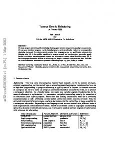
Fig. 10 shows the general architecture of the EdDL approach. A key aspect is that Editor Engine (EE) relies on Graphical Diagramming Engine (GDE) for all diagram drawing related activities. The primitives implemented by GDE - diagram, box, line, compartment etc. and the supported operations on them are very fit for this framework. Thus the interface between EE and GDE is based on very appropriate high level building blocks, there is no need for low level graphical operations in EE at all. The GDE itself was developed by IMCS UL initially within the framework of ADDE project, with a commercial version later on. It is based on very sophisticated graph drawing algorithms [13]. The general technology of using EdDL for defining a set of editors is quite simple. For each diagram type in the modelling methodology the corresponding editor definition is built on the basis of the relevant domain metamodel fragment and using an appropriate diagram core from the core library. Then these definitions are parsed and assembled into one set. EE
12
Audris Kalnins, Janis Barzdins, Edgars Celms, Lelde Lace, Martins Opmanis, Karlis Podnieks, Andris Zarins
"performs" this set, behaving as a modelling tool containing the defined set of diagrams. A lot of tool functionality, e.g., “small operations" such as copy-paste are implemented in EE in a standard way and need no special definitions. Certainly, external modules can also be included for some domain-specific operations.
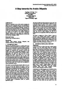
Figure 11. Editor in action Actually EE runs under the guidance of the Generic modelling framework (GMF), which directly manages the repository and incorporates also other non-diagrammatic generic editors. It is universally accepted nowadays that the logical metamodel describes directly (or very close to it) the physical structure of the tool repository. According to this principle all data-related operations within GMF are metamodel based, various repository formats such as OODB, a special tool repository, a relational DB or even a file in XML format are supported in a uniform way. All model-level operations such as load and save are also automatically supported by the framework. But the most important feature of this framework is the possibility to define a flexible model content browsing – via rich model tree definition facilities, based on the same metamodel. A very brief schema for defining a model tree is the following. An arbitrary tree starting with a root node and consisting of two kinds of nodes : constant nodes (representing some fixed text) and object nodes (representing instances of one class contained in the model) is defined. Then during the usage of this tree an object node is replaced by the set of nodes corresponding to all these instances. But the most non-trivial feature of this approach is the definition of selection rules for object nodes. For any object node a selection rule can be specified, saying which of the possible instances actually must appear in the tree. To be short, a selection rule is a Boolean expression on link conditions (specifying that a certain sequence of metamodel associations must link the given node to a node higher in the
TitleThe First Step Towards Generic Modelling Tool
13
tree) and attribute value conditions . The actual expression language can contain some more details (including simple existential quantifiers), but even the mentioned features permit to define nearly any reasonable “treeview” on the model contents. Recursive tree definitions are also supported. The definition facilities permit also to define action lists (edit, new, delete etc.) for any node, thus e.g. all the links between the model tree and diagram editors are supported automatically by the framework. The left pane in Fig. 11 shows one of the possible model trees for the Business activity modelling, defined via the described facilities. The first commercial version of Generic Modelling Framework has been implemented. The flexibility of the approach has been tested by implementing full UML 1.3 (except sequence diagrams) and various specific business process notations. The implementation has a special feature that e.g. the same business process may be alternatively presented as a UML Activity diagram or IDEF3 process chart. The defined editor sets (like the one in Fig.11) have reached the industrial quality of typical modelling tools, with all the required user support.
5.
CONCLUSIONS
The practical experiments have demonstrated that the above described metamodel-based graphical editor implementation method is realistic and can reach an industrial quality. However this approach can be made significantly more universal, since it is generally accepted that a metamodel (class diagram) can be used for describing the logical structure of nearly any system. Thus the same approach of extending this model by special “presentation” classes could be used, e.g. to define dynamic semantics of the model, its simulation etc., but this is out of scope for this paper.
References [1] Kalnins, A., Barzdins, J., Podnieks, K., Zarins, A. et al. Business Modeling Language GRAPES-BM and Related CASE Tools. Proceedings of the Second Baltic DB&IS'96, Institute of Cybernetics, Tallinn, 1996, pp.3-16 [2] Advanced Business and System Modeling Tools, http://www.gradetools.com/ [3] Smolander, K., Martiin, P., Lyytinen, K., Tahvanainen, V-P.: Metaedit – a flexible graphical environment for methodology modelling. Springer-Verlag, 1991. [4] MetaEdit+: Technical Summary. http://www.metacase.com/papers/index.html [5] Ebert, J., Suttenbach, R., Uhe, I.: Meta-CASE in Practice: a Case for KOGGE. Proceedings of the 9th International Conference, CAiSE'97, Barcelona, Catalonia, Spain , 1997, pp.203-216
14
Audris Kalnins, Janis Barzdins, Edgars Celms, Lelde Lace, Martins Opmanis, Karlis Podnieks, Andris Zarins
[6] Ledeczi A., Maroti M., Bakay A., Karsai G., Garrett J., Thomason IV C., Nordstrom G., Sprinkle J., Volgyesi P.: The Generic Modeling Environment, Workshop on Intelligent Signal Processing, Budapest, Hungary, May 17, 2001 [7] DOME Users Guide. http://www.htc.honeywell.com/dome/support.htm [8] Esser, R.: The Moses Project. http://www.tik.ee.ethz.ch/~moses/MiniConference2000/pdf/Overview.PDF [9] ESPRIT project ADDE. http://www.fast.de/ADDE [10] Sarkans, U., Barzdins, J., Kalnins, A., Podnieks, K.: Towards a Metamodel-Based Universal Graphical Editor. Proceedings of the Third International Baltic Workshop DB&IS, Vol. 1. University of Latvia, Riga, (1998) 187-197 [11] Kalnins, A., Podnieks, K., Zarins, A., Celms, E., Barzdins, J. Editor Definition Language and its Implementation. Proceedings of the 4th International Conference "Perspectives of System Informatics" , Novosibirsk, 2001, pp.278-281 [12] Rumbaugh, J., Booch, G., Jackobson, I.: The Unified Modeling Language Reference Manual. Addison-Wesley (1999) [13] Kikusts, P., Rucevskis, P.: Layout Algorithms of Graph-like Diagrams for GRADEWindows Graphical Editors. Lecture Notes in Computer science, Vol. 1027. Springer-Verlag, 1996 pp.361-364 [14] Gamma, E., Helm, R., Johnson, R., Vlissides, J. Design Patterns. Addison-Wesley, 1995. [15] Meta Object Facility (MOF) Specification, OMG, 2001 (http://www.omg.org)