TMS320C6713-DSP Based FSK Modem with Receiver Synchronisation Sithamparanathan Kandeepan
Leif Hanlen
Wireless Signal Processing Group National ICT Australia Canberra, Australia Australian National University
[email protected]
Wireless Signal Processing Group National ICT Australia Canberra, Australia Australian National University
[email protected]
Abstract—In this paper we present a Texas Instrument’s TMS320C6713- DSP based communication testbed, designed for testing signal processing algorithms, channel measurements and performance analysis of digital receivers. As an example, the testbed is used to implement a frequency shift keying (FSK) modem with synchronisation capabilities at the base band, which we present here. The modem operates at a data rate of 600bps with a sampling frequency of 48 KHz. Here, we present the design and architecture of the modem, and some results obtained using Matlab.
I.
INTRODUCTION
Bringing communications and signal processing [1-4] from theory to practice is one of the many things that researchers tend to do, especially to verify their analytical models, designs and algorithms. Here, at the Wireless Signal Processing group at the National ICT Australia, we design a communications and signal processing testbed to serve the same. The testbed is based on the Texas Instrument’s floating point DSP with additional modules, such as audio daughter cards, attached to it. The Texas Instruments TMS320— series DSP platforms [5-8] are well known in terms of fast prototyping and used throughout academia and industry. In this paper we outline a particular application of the TMS320C6713-DSP platform for use as an FSK modem. The modem is designed for research purposes to test channels, and implement signal processing algorithms for communications systems. For the purpose of this paper we outline the implementation of a simple binary frequency-shift-key modem. The modem operates at a sampling frequency of 48kHz, and has carrier frequencies of 1.2kHz and 2.4kHz. The BFSK modem runs Matlab on top of the DSP software which is similar to a software-defined base band processor. The frequency synchronization at the receiver [9-17] is not considered in this implementation. Initially we introduce the hardware platform of the test-bed, which is the Texas Instrument’s C6713 family of DSP, followed by the software modules and the communication systems architecture. Finally, we present some experimental results
obtained from the software based FSK modem and test its functionality. II.
TEST-BED HARDAWRE
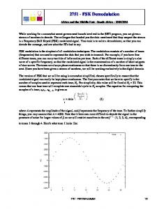
The communications and signal processing test-bed uses the Texas Instruments TMS320C713 [21,22] development board as the base band processor connected to a host computer (PC). In the future the development board is to be attached with a direct up-converter and a down-converter module which directly up-converts and down-converts the base band signal to the ISM band. In this work, we present only a base band module dealing with audio range frequencies. The development board is supported by a software tool called the code composer studio (CCS) [27,28] by the manufacturer, which includes the necessary board and chip support libraries (BSL and CSL) [31] that enables the user to initiate and access the onboard subsystems such as the onboard memory module, memory interfaces etc. Figure-1 shows the block diagram of the development board and its major (but not all) onboard subsystems. As shown in the figure the board includes a floating point C6713 DSP [21,22] running at a speed of 225MHz, an AIC23 [20] based ADC/DAC module, which is an audio codec, 16MB onboard memory and 256KB flash memory, memory interface, multi-channel buffered serial port (McBSP) [25, 26], a USB interface to the host PC and a dc power connector with a voltage regulator. The audio codec is connected to the DSP through two McBSP interfaces, McBSP0 and McBSP1. McBSP0 is used for controlling the audio codec and McBSP1 is used for data transfer. The USB connection to the host PC is through an embedded Joint Target Action Group interface (JTAG), and the onboard memory is connected via the Enhanced Memory Interface (EMIF). The board also contains other subsystems such as the memory expansion interface, peripheral expansion interface, external JTAG, four dip switches and four light emitting diodes which are controllable through software.
A. AIC23 Audio codec The AIC23 audio codec is the analog signal interface to the base band processor with four 3.5mm audio pin sockets for input and output purposes. Out of the four pins, there are two stereo input channels (line-in and microphone-in) and two stereo output channels (line-out and headphone-out) with a voltage level of 6 volts peak to peak on the analog side. The codec utilizes the sigma-delta technique that achieves high resolution at low sampling frequencies. The codec can be configured to change its sampling frequency up to a maximum of 96kHz which is driven by a 12MHz crystal clock. In our design we set the sampling frequency to 48KHz. The sampled input signal is passed through an interpolation filter, modulator and a decimation filter, which are on the codec circuit, to achieve high signal to noise ratio. The samples are then converted into digital data using 2’s complement, which are readily accessed by the DSP for further processing. The data transfer is performed through the McBSP interface using hardware interrupts. For signal output, the signal samples are shaped by a low pass filter, which gives an analog signal at the output of the DAC. III.
MATLAB IMPLEMENTATION
The intention of the Matlabtm interface of the testbed is to encourage fast implementation of the communication tools onto the DSP platform. We have deliberately avoided “addon” software such as Simulink, Matlab toolboxes and the DSP’s own Matlab interface for the following two reasons: 1) They are not universally available, particularly for students using education versions of Matlab software. 2) The Simulink-style boxes tend to limit the functionality of the DSP platform to a well-developed subset of DSP uses. While choosing to not use the complete gammit of toolboxes etc, may seem to limit the applicability of the tools, it is our hope that we may more easily find a balance between ease of use, and realistic flexibility in terms of testbed implementations. The Matlab interface is described in figure 2. The modem comprises basic aspects of common communication systems – character to binary conversion, buffering (achieved on disk or by using Real Time Data Exchange RTDX) some minor forward error correction and correlation decoding. The objective of the modem is not to provide a novel FSK system, but through its simplicity facilitate further development. At its core, Matlabtm is a script-based language. Although newer instantiations, such as the real-time toolbox provide some process-based applications, the majority of code written in Matlabtm is linear. The initial process model for the matlab modem was to use while(true)...end language constructions, however these were replaced with timer objects. The matlab timer object is defined as a standard inclusion in Matlab 5 and above, and allows functions to be activated outside the normal linear operation of a Matlab script.
Figure-2, Matlab interface, Processes are driven by timer objects, which are controlled centrally through a graphical user interface
With sufficiently small (low complexity) functions, and timer periods of 0.1–0.5 seconds, the modem appears to run in real time. The advantages of the timer-based over the continuous while(true)...end loops are two-fold: the processes can be arbitrarily timed – faster or slower – and may be run asynchronously. The asynchronous component of the timer, allows user to stop and start the execution of program easily from a main control window. A. Transmitter The transmit side of the modem uses a simple bitstream, saved in a text file for the DSP to read. The file is controlled through a semaphore [20] based system. The current arrangement requires both the DSP and the Matlab code to open a locking file which contains a single text character which may be in one of two states – read or write – which controls over-writing of data. The bit stream is re-generated through the use of a small Matlab function which is called through the use of a timer object. The file is then read by the DSP code, which creates a BFSK sequence of samples. B. Packet structure At present the modem has no feed-back channel – so repeat requests are not possible. The data frames are designed to be robust against erasure. The modem uses a series of frames, with a fixed number of bits. We have used 17 bits per frame, described as follows:
C. Receiver The receiver side of the Matlab code consists of three timer controlled processes: detect The detector uses a correlator (matched filter) system to match the received FSK samples to known frequency sinusoids. This provides soft data outputs, which are given to the decoder.
•
• decode The current decoder uses a simple nearest neighbour threshold test to determine the bit value. The structure of the matlab system is designed to allow arbitrary decoders to be “plugged in” and replace the threshold test.
received power based on a threshold value, once the signal is acquired, the received signal samples are saved for further processing. Frame synchronisation is also performed simultaneously with signal acquisition, and is done using the synch-pulses transmitted at the beginning of each frame. After achieving frame synchronisation the frame is passed through the timing synchronizer and the correlator for signal detection. The timing synchorniser feeds the correlator with the timing information to appropriately sample the output of the correlator. The timing synchronisation is performed with the use of a threshold detector based on the synch-pulse that was used for frame synchronisation. r
Signal Acq
detected bits
Correlator
Frame Synch
Bank
display The display function provides simple output for the data, including a constellation diagram, real-time detector output along with bit error results.
Detector
•
IV.
FSK MODEM ON DSP
In this section we explain the design of the FSK modem/base band processor implemented on the DSP development board. The modulation that is used is binaryFSK, that switches between two frequencies depending on the data whether ‘0’ or ‘1’. The two frequencies used for transmission are f0 = 1200Hz and f1 = 2400Hz. These frequencies were selected to have an integer ratio value between the sampling frequency and the corresponding frequencies. That is, fs/f0 = 40 and fs/f1 = 20. The block diagrams of the transmitter and the receiver are depicted in Figure-3 and Figure-4 respectively. The transmitter receives the binary data from the application (which is Matlab) and maps it into the corresponding waveforms S0 or S1 with tones either f0 or f1 respectively. The two tones are generated using a look-up table with pre-calculated values. The waveforms are then grouped into a frame with a pulse attached to the front end of the frame. Every frame contains 17 bits with a synchronisation impulse. The impulse is used for symbol timing [12] and frame synchronisation purposes at the receiver. The effective transmission rate of the overall bit stream is 600bits/sec, which gives a total of 80 samples per bit, with S0 having 2 cycles per bit and S1 having 4 cycles per bit. The transmitted signal r(t) is given by, r(t) = Acos(2πfit)
(1)
where, fi is the frequency corresponding to the input bit, and A is the signal amplitude. FSK Tone Selector (Symbol Mapping)
Binary data
S0
Timing Synch
S1
Framing
r
Figure-4, Binary FSK receiver module
This technique however needs to be modified depending on the bit rate and the sampling frequency. It counts the number of samples after detecting the synch-pulse to achieve bit timing. The soft decisions made at the output of the correlator are passed through the detector, which is a maximum likelihood (ML) [1-3] threshold detector that makes hard decisions. The correlation and detection processes are performed on Matlab, where as the synchronisation is performed on the DSP. The receiver control unit of the base band processor on the DSP is shown in Figure-5. When the board is turned on the receiver initializes and looks for any signal present at the input. In the absence of any signal, the receiver goes to an idle mode. If a signal is detected at the input, the receiver goes to the signal acquisition mode as shown in the figure. Initialisation command Initialisation
Idle command
Acquisition command
Signal acquisition state
Idle state
Acquisition command Idle command
Synchroisation command Synch and Receive state
gp Signal Receive
Tone Generator f0 and f1
Pulse Generator
Figure-5, Receiver control unit, state diagram Figure-3, Binary FSK transmitter module
At the receiver, the signal is acquired by estimating the
I2
I1
USB
Power
C1 AIC23 codec
I3
I4
C6713 DSP
C2
I5
SDRAM C3
I1 – Host PC connection I2 – DC power connection I3 – Line-in I4 – Microphone-in I5 – Line-out I6 – Headphone-out
I6
C1 – JTAG interface C2 – McBSP interface C3 – EMIF
Figure-1, Test-bed hardware, DSP development board and its main functional subsystems Received Signal - Real Time
1000 0 8000
Amplitude
6000 4000 2000 0 -2000 0
100
200
300
400
500 Time samples
600
700
900
Binary Decisions - Real Time 2
0. 8 0. 6 0. 4 0. 2 0
1. 5 1 Amplitude
1
-0.2
0. 5 0 -0.5
-0.4 -1 -0.6 -1.5
-0.8 -1 -5
-4
-3
-2
-1
0 Inphase
1
2
3
4
-2
5
0
2
4
6 n
8
10
12
10
20
50
100
200
400
600
800
1000
1500
2000
4000
8000
0.2630
0.3962
0.4363
0.4515
0.4547
0.4520
0.4535
0.4522
0.4487
0.4450
0.4487
0.4500
Gain (dB)
0.1412
f- Hz
5
Figure-8, Real-time received signal, detector output and the binary decisions performed by the FSK receiver
0.0560
Quadrature
Constellation Diagram - Real Time
800
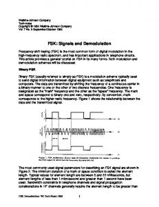
Table-1, Experimental measurements of channel response from DSP-1 to DSP-2
V.
EXPERIMENTAL SETUP
The testbed includes two host PCs, two TMS320C6713 based DSP development boards, an audio range oscilloscope and a function generator. The experimental setup is shown in Figure-5. Each of the DSP boards are attached to a PC through the USB interface and the two DSP boards are connected using a single 2 metre 3.5mm audio cable.
to the a.c. coupling circuits on the audio codec to avoid dc offsets appearing in the received signal. Further, the channel also shows some noise effects. 100
Gain
Once the signal is acquired the receiver goes to the signal receive state performing frame synchronisation, and the signal samples are then passed on for detection.
10-1
10-2
0
10
1
10
2
3
10
4
10
5
10
10
frequency
Figure-6, Channel frequency response, DSP-1 to DSP-2
The DSP boards are supplied with two different external power sources. Further, the output from the transmitter, which is DSP-1, is also connected in parallel to the CRO. DSP-2 is the receiver which waits for an input signal when it is switched on. The real time data between the DSP boards and the corresponding host PCs are passed through the USB interface for processing and post analysis. VI.
FSK MODEM TEST RESULTS
We conducted some testing to study the channel response at different frequencies. The channel is considered as a black box which includes the transmitter audio codec, transmission cable and the receiver audio codec. We also studied the low frequency noise effect of the channel. To study the channel response, we transmitted single-tone signals with different tones and recorded the received signal amplitude. This was done by maintaining the gains of the ADC and the DAC constants at the receiver and the transmitter respectively. The channel response is measured in terms of the numerical values read from the ADC corresponding to the voltages at the input of the ADC. The resolution of the codec is 16-bits, the received signal amplitude varies between -215 to (215 -1). Table-1 shows the experimental results measured at the receiver for the channel response. The results in Table-1 are also depicted in Figure-6. From the results we see that the channel is flat other than at very low frequencies. At very low frequencies and d.c., the codec tends to suppress the signal. This is due
theory experiment
0.30 0.25
0.2 PDF
Figure-5, Testbed setup
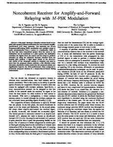
The noise is not uniform due to the nonlinear elements, such as the quantiser, in the codec. The higher frequency (f > 100Hz) noise is reduced by the up- and down-sampling processes in the codec. Experiments were conducted to study the statistical nature of the low frequency channel noise from DSP-1 to DSP-2. The receiver was turned on while DSP-1 was transmitting all zeros. Figure-7 shows the statistical distribution of the low frequency channel noise, which follows a Gaussian distribution. The low frequency noise has zero mean and a variance of 2.1868 in terms of the amplitude.
0.15
0.1 0.05
-6
-4
-2
0
2
4
6
n - noise samples
Figure-7, Low frequency channel noise, DSP-1 to DSP-2
Having studied the transmission channel, we then tested the FSK based transmitter and receiver. The received raw signal samples, output samples from the correlators and the binary decisions made by the detector were recorded for test analysis and compared with the actual transmitted signal and data. Figure-8 depicts the recorded data, and from the figure we see that the receiver and the transmitter are functioning as per design expectations.
VII. FUTURE WORK The DSP based test bed presented in this paper is a base for many future work and experiments. Currently, we are in the process of designing an OFDM based communication system on the same hardware. In the near future, a multichanneled daughter card is to be attached to the DSP board. With the daughter card attached to the DSP board, and an RF interface attached to the daughter card, we plan to implement a wireless based multi-input multi-output (MIMO) systems. Such a system will allow us to conduct many experiments such as MIMO channel measurements and channel correlation, and testing synchronisation and receiver algorithms for MIMO based wireless systems. VIII. CONCLUSION We presented a communications and signal processing test bed based on the TMS320C6713 based DSP. The test bed is designed to be used for research purposes. In this paper, we have given a binary-FSK based modem, with system architecture, hardware design and the software design which runs as an application on top of the DSP based testbed. The FSK modem was tested on its functionality, and we have presented some real time data recorded at the receiver. We have estimated the channel transfer function for the modem and the noise statistics of the same at low frequencies as well. ACKNOWLEDGEMENT The authors would like to thank the Wireless Signal Processing Program at the National ICT Australia. National ICT Australia is funded through the Australian Government’s Backing Australia’s Ability initiative, in part through the Australian Research Council. L. Hanlen and S. Kandeepan are also with the Research School of Information Sciences and Engineering at the Australian National University in Canberra. REFERENCES [1] B.Sklar, Digital Communications, Fundamentals and Applications: Prentice Hall, 1988. [2] S.Benedetto, E. Biglieri, and V. Castellani, Digital Transmission Theory: Prentice Hall, 1987. [3] J.G.Proakis and M. Salehi, Communication Systems Engineering: Prentice Hall, 1994. [4] M.C.Jeruchim, P. Balaban, and K. S. Shanmugan, Simulation of Communication Systems, Modelling, Methodology and Techniques, 2nd ed: Kluwer Academic/Plenum Publishers, 2000. [5] R. Chassing, Digital Signal Processing and Applications with the C6713 and C6416 DSK, John Wiley & Sons, 2005. [6] R.Chassing, DSP Applications Using C and TMS320C6x DSK: John Wiley & Sons, 2002. [7] N. Kehtarnavaz and B. Simsek, C6X-Based Digital Signal Processing: Prentice Hall, 2000. [8] N.Dahnoun, DSP implementation using the TMS320C6000 DSP platform/Naim Dahnoun, 1st ed. Harlow, England, New York, Prentice Hall, 2000 [9] S. Kandeepan, Synchronisation techniques for digital modems, PhD thesis, University of Technology, Sydney, 2003
[10] S. Kandeepan and S. Reisenfeld, “Acquisition Performance of a Digital Phase Locked Loop with a Four-Quadrant arcane based Phase Detector”, IEEE International Symposium on Intelligent Signal Processing and Communications, Nov 2004. [11] S. Kandeepan and S. Reisenfeld, “Performance Analysis of a Correlator Based Maximum Likelihood Frequency Estimator”, IEEE International Conference on Signal Processing and Communications, Dec 2004 [12] S. Kandeepan and S. Reisenfeld., "DSP Based Timing Estimation Techniques" Fourth International Conference on Information, Communications & Signal Processing and the IEEE Pacific-Rim Conference On Multimedia Proceedings, Dec 16-18 2003, Singapore. [13] S. Kandeepan and S. Reisenfeld, "Frequency Tracking and Acquisition with a Four-Quadrant arctan Phase Detector Based Digital Phase-Locked Loop" Fourth International Conference on Information Communications & Signal Processing and IEEE Pacific-Rim Conference on Multimedia Proceedings, Dec 16-18 2003, Singapore. [14] S. Kandeepan and S. Reisenfeld, "DSP Based Frequency Estimation Techniques and Their Relative Performances", Symp on Communication Systems, Networks and Digital Signal Processing (CSNDSP2002), July 15-17, Staffordshire. [15] S. Kandeepan and S. Reisenfeld, "Frequency Jitter of a Digital Phase-Locked Loop and comparison with a Modified CRB", IEEE International Conference on Communication Systems 2002, Nov 25-29. Singapore. [16] S. Kandeepan and S. Reisenfeld, "Phase Detector Models and Their Performances for IF/Baseband Frequency Recovery For Complex Envelope Based DSP Implemented PLL", IEEE Int Conf on Communication Systems (ICCS 2002), Nov 25-29. Singapore. [17] S. Kandeepan, and S. Reisenfeld, "A Complex Envelope Based 2nd Order Digital Phase Locked Loop and its Performance", IEEE International Symposium on Intelligent Signal Processing and Communication Systems 2001(ISPACS 2001) Proceedings of, Nov 20-23, Nashville [18] B. D. Hahn, Essential MATLAB for scientists and engineers,2nd ed. Oxford, Butterworth-Heinemann, 2002. [19] J. G. Proakis and M.Salehi, Contemporary Communications Systems Using Matlab, Brooks/Cole Thomson Learning, 2000 [20] W. H. Stallings, Operating Systems, 4th ed. Upper Saddle River, New Jersey 07458: Prentice-Hall, 2001. [21] How to Begin Development Today with the TMS320C6713 Floating Point DSP, SPRA809, Texas Instruments, Dallas, 2003 [22] TMS320C6713 Floating point Digital Signal Processor, SPRS186, Texas Instruments, Dallas Texas [23] TMS320C6000 Programmers Guide, SPRU198G, Texas Instruments, Dallas, Texas, 2002 [24] TMS320C6000 CPU and Instruction Set Reference Guide, SPRU189F, Texas Instruments, Dallas, Texas, 2000 [25] TMS320C6000 Peripherals Reference Guide, SPRU190D, Texas Instruments, Dallas, Texas, 2001 [26] TMS320C6x Peripheral Support Library Programmers Reference, SPRU273B, Texas Instruments, Dallas, Texas, 1998 [27] Code Composer Studio Users Guide, SPRU328B, Texas Instruments, Dallas, Texas, 2000 [28] TMS320C6000 Code Composer Studio Tutorial, SPRU301C, Texas Instruments, Dallas, Texas, 2000 [29] TLV320AIC23 Stereo Audio Codec, 8- to 96-kHz, with Integrated Headphone Amplifier Data Manual, SLWS106G, Texas Instruments, Dallas, Texas, 2003 [30] TMS320C6000 DSP/BIOS User Guide, SPRU423, Texas Instruments, Dallas, Texas, 2002 [31] TMS320C6000 Chip Support Library API User’s Guide, SPRU401F, Texas Instruments, Dallas, Texas, 2003