MICI5.S-305
2011 IEEE Nuclear Science Symposium Conference Record
Tomographic images by proton Computed Tomography system for proton therapy applications Valeria Sipala, Mara Bruzzi, Mirko Brianzi, Marta Bucciolini, Giuseppe Antonio Pablo Cirrone, Carlo Civinini, Giacomo Cuttone, Domenico Lo Presti, Stefania Pallotta, Nunzio Randazzo, Francesco Romano, Monica Scaringella, Concetta Stancampiano, Cinzia Talamonti, Mauro Tesi.
Abstract-Proton therapy is a highly precise form of cancer treatment,
which
requires
accurate
knowledge
of
the
dose
silicon
tracker
and
a
Y AG:Ce
calorimeter.
The
image
reconstruction technique uses data of the single particle
delivered to the patient and verification of the correct patient
trajectory in order to overcome the limits due to the Multiple
position
Coulomb Scattering (MCS) of the proton in the matter. The
to
avoid
damage
to
critical
normal
tissues.
The
development of pCT (proton Computed Tomography) system represents an important feature for precise proton radiation treatment
planning
measurement
of
because
the
it
proton
could
stopping
permit power
the
direct
distribution,
improving the accuracy in dose calculus, and the patient's
apparatus was tested at Laboratori Nazionali del Sud (LNS) using a 60MeV proton beam. During this test radiographic images of PMMA phantoms were taken. Phantoms with different density zones have been used to estimate the system
to
performances (spatial and energy resolution). Moreover, a
demonstrate the capability to acquire, during treatments in
tomographic image was acquired mounting a cylindrical
position.
A
pCT
prototype
was
manufactured
in
order
proton therapy centers, radiographic and tomographic images
phantom, with embedded in-homogeneities, on a rotating
according to clinical demands.
system to provide multiple projection angles. Preliminary results
I.
INTRODUCTION
Computed Tomography
(pCT)
is
an
imaging
Ptechnique able to reconstruct 3D images containing proton ROTON
obtained using the Filter Back Projection
(FBP)
reconstruction algorithm. Different reconstruction algorithms, based on the tracking information, are presently under test.
stopping power information that can be used to simulate and II.
plan the proton treatment. Nowadays X-ray tomography (X CT) is used for proton treatment planning but there are fundamental
differences
in
the
interaction
mechanisms
The
apparatus,
ApPARATUS ARCHITECTURE developed by
Italian
PRIMA
(PRoton
IMAging) collaboration, is able to acquire tomography images
between X-rays and protons. The conversion of the Hounsfield
by proton beam. The goal is to demonstrate that it meets
coefficients from the X-ray CT into proton stopping power
clinical demands for the use of protons in radiotherapy
introduces an intrinsic error (1]. A pCT system, using the same therapeutic proton beam, could produce images avoiding these conversion uncertainties resulting in a better dose accuracy. Starting from these potential advantages of pCT and from the growing interest about proton therapy treatments, a 2 pCT prototype with 5x5cm active area has been designed, manufactured and tested [2-7]. This prototype consists of a Manuscript received November 14, 2011. This work was supported by INFN (CSNS) and MIUR]RIN 2006. V.Sipala is with the Istituto Nazionale di Fisica Nucleare (INFN) of Catania and University of Sassari, 4, Via Piandanna, 1-07100 Sassari, Italy (telephone: +39079229488, e-mail:
[email protected]). M. Bruzzi, M. Scaringella and M.Tesi are with INFN of Florence and Energetic Department, University of Florence, Italy. M. Bucciolini, S. Pallotta and C. Talamonti are with INFN of Florence and Clinical Physiopathology Department, University of Florence, Italy. C. Civinini and M. Brianzi are with INFN of Florence, Italy. N.Randazzo is with INFN of Catania, Italy. D. Lo Presti and C. Stancampiano are with INFN of Catania Department of Physics - University of Catania Italy. G.A.P. Cirrone and G. Cuttone are with INFN- Laboratori Nazionali del Sud, Catania, Italy. F.Romano is with INFN- Laboratori Nazionali del Sud and Centro Studi e Ricerche e Museo Storico della Fisica "Enrico Fermi", Roma, Italy
978-1-4673-0120-6/11/$26.00 ©2011 IEEE
treatments, spatial resolution lower than Imm and density energy resolution lower than 1% [8]. The principal problem in the image quality is due to the Multiple Coulomb Scattering (MCS) of the proton in matter. The pCT prototype manufactured by our collaboration is based on the single proton tracking with the aim of using this information in the reconstruction technique. The apparatus consists of a silicon tracker and a Y AG:Ce calorimeter. Silicon detectors in front of and behind the object to be imaged provide spatial coordinates and direction of single protons and Y AG:Ce scintillating crystals measure its residual energy. From these measurements,
by a semi analytical
algorithm, the Most Likely Path (MLP) [9] is calculated and applied in the image reconstruction.
2 The system has a field of view of about 5x5cm , acquisition 5 times in the order of lOs (lOkHz, 10 events), it has been optimized to detect protons with energy in the range of 200250MeV (the energy needed to traverse a human head and trunk respectively) and to sustain potentially IMHz data acquisition rate. Apparatus details were described in previous
3505
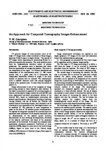
works [2-7] where first results obtained with a 60MeV proton beam at LNS were discussed. Fig. 1 shows the picture of the LNS, more quantitative measurements were carried out to
Dhole Dsmm
determine the spatial resolution and the electronic density
DlOmm
apparatus located along the beam line. During the test beam at
resolution.
Radiographic projections of phantoms were 7 performed acquiring 10 events. Details of the results will be presented in the next section.
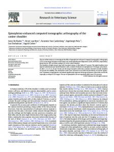
Fig. 3. Draft of the PMMA phantom irradiated with 60MeV proton beam which of the radiographic image has been analyzed. Different density zone are obtained with holes of different depth. The dimensions of holes and the reciprocal distances are shown.
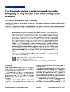
Fig. 1. Picture of the pCT prototype located in the beam line at LNS. Four x-y planes of the tracker are visible. Tomographic images were acquired using the setup shown in Fig. 2. A cylindrical phantom with two empty zones of known sizes was located between the tracker planes P2 and P3. To provide multiple projection angles, the phantom was mounted on a rotating support. The object was irradiated at angles between 0 and 360 degrees in steps of 10 degrees and 6 for each angle 2x10 events were acquired.
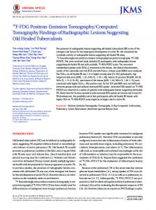
Data have been acquired and analyzed off-line. In Fig. 4 the phantom radiographic image obtained is shown. The spatial coordinates of the single proton path, acquired in the plane nearest to the phantom, have been correlated with residual energy value measured by the calorimeter. The maximum energy
value
is
about
55MeV,
whereas
25MeV
is
the
minimum value: SRIM code [10] confirms that the residual energy values measured are comparable with energy loss values obtained in simulation phase. Four different density zones can be distinguished and the spatial resolution is able to reconstruct all holes. In order to understand the spatial resolution of pCT apparatus, an image profile is obtained
Rotating
starting of this image and shown in Fig. 5. The good spatial resolution is supported by these data: between 55MeV and 20MeV the sigma is equal to 3 strips (600flm).
Beam
P1
P2
Phantom P3
P4
Calorimeter
Fig. 2. Schematic display of the setup used for tomographic images acquisition. The rotating phantom is positioned between four planes (PI-P4) of the tracker, while the calorimeter is at the end of the particle path.
Ill. A.
RESULTS
Radiography images
PMMA
phantoms
have
been
placed
inside
the
pCT
apparatus along the proton beam line at LNS. The main aim was to acquire and to reconstruct radiographic images. In particular a PMMA phantom with different density zone has 7 been irradiated and 10 events have been acquired. The phantom is a cylinder with 2 cm of thickness and holes of different depth. Four different zones were manufactured: empty hole and holes 5, 10 and 15 mm thick. The Fig. 3 shows the draft of the phantom just described.
Fig. 4. Color map of PMMA phantom irradiated at LNS with 60MeV proton beam (see Fig. 3). With different colors are indicated the residual proton energy value (the values are expressed in MeV.
3506
energia
vs x,
IV.
135