Tool deformation during the shape rolling of stator vanes H.H. Wisselink1 , J. Hu´etink1 1
Netherlands Institute of Metals Research; University of Twente, P.O.box 217, 7500AE Enschede, The Netherlands URL: www.nimr.nl; www.tm.wb.utwente.nl e-mail:
[email protected];
[email protected]
ABSTRACT: Tool deformation is an important issue in the shape rolling of stator vanes as it directly influences the thickness of the rolled vane. This means that for the design of an accurate production process the deformation of the tools has to be accounted for. The shape rolling of symmetrical straight vanes has been investigated. This rolling process is considered stationary, because these vanes have a constant cross-section over the length. Therefore an ALE formulation is suitable to calculate the steady state. The deformation of the sheet as well as the deformation of the tools have been calculated with the developed finite element model. Some results of these simulations are presented in this paper. Key words: shape rolling, tool deformation, ALE 1
INTRODUCTION
A method to manufacture stator vanes for gasturbines or aero engines is a cold shape rolling process, which will be explained in more detail in Section 2. The thickness of a strip of sheet material is reduced during this rolling process, in order to obtain the right thickness at the right position at the right cross-section of the vane. However, thickness deviations can be found after the first trial runs. One important reason for these deviations is the deformation of the rolling tools. If the deviations are too large, the tools or process parameters have to be adapted. Unfortunately sometimes a number of process redesign cycles are necessary to produce vanes within the required tight tolerances. In order to improve the design of the rolling tools for new types of vanes, more fundamental knowledge is needed. Therefore this process has been modelled, which should give more insight in this process. The results of a FEM model with rigid tools have been described in [1]. In this paper a FEM model is presented in which the rigid tools have been replaced by deformable tools. 2
THE SHAPE ROLLING PROCESS
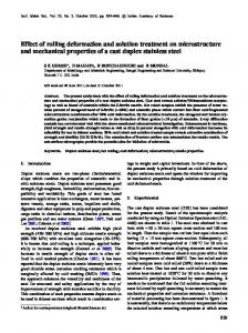
The tools used for the shape rolling process are drawn in Figure 1. Both tools, the roll-die and die-plate con-
tain the profile of the vane. Only one of the tools, the roll-die, rotates, which differs from the usual shape rolling process. The other tool, the die-plate is fixed to the frame of the machine.
Fvertical Fhorizontal
Roll-die Die-plate Figure 1: Tools for the rolling process.
The roll-die rolls over the die-plate, due to the applied horizontal force and a cog-wheel construction. This deforms the strip, which is clamped to the die-plate on one end, into a vane. The length of the final product is limited to the perimeter of the roll-die. The vertical force, applied through a support roll, controls the vertical movement of the roll-die. Normally, the roll-die makes contact with the die-plate during rolling. How-
ever, when the applied vertical force is too low the roll-die will be lifted. The vane, which will be investigated in this paper, is produced by the tools of Figure 2(a). Experimental data are available [2] for this product to validate the simulations. The shape of this symmetrical straight vane is similar to the shape of a real vane. The vane is 2 mm thick in the middle and 1 mm thick at the leading and trailing edges. Besides elongation, lateral spread is made possible with a gutter next to the vane profile. 3
ALE METHOD
When the start and the end of the process are neglected, the rolling of straight vanes can be considered as a stationary process. In that case the roll-die rotates only and the die-plate moves opposite to the rolling direction. The ALE method is an appropriate method for calculating the steady state of a stationary process. The grid displacements are independent of the material displacements in this formulation. Therefore it is possible to model the shape rolling process as a flow problem, while following free surfaces, keeping elements at regions with large deformations and preserving a sufficient element quality. The used finite element code DiekA, developed at the University of Twente, contains such a ALE formulation. 3.1
Contact
Special contact elements are used to describe the contact between the strip and the tools. These elements are based on a penalty formulation [3]. The nodes of the contact elements have to be connected to the two contacting bodies. A pair of contact nodes should be opposite to each other during the entire simulation in order to calculate a correct penetration distance. It is shown in [3] for a 2D rolling application, that this is possible for stationary processes, using the ALE method. However this gives the extra condition, that contacting surfaces should have an equal mesh, which complicates the meshing of the tools and the vane. 3.2
tively 7748, 3640, 6006 and 1408 elements are used for the die-plate, strip, roll-die and contact. A rotation is prescribed to the mid plane of the rolldie. The die-plate and the vane get an equal prescribed displacement at the outflow, where the vane is clamped to the die-plate. The vertical force is applied to the bottom face of the die-plate, which was the easiest solution. Therefore the die-plate can move up and down instead of the roll-die, but the mutual displacement is not influenced. Every step the mesh displacement is calculated such that the mesh movement is kept fixed in rolling direction. Therefore the material ”flows” through the mesh in rolling direction, which results in in- and outflow boundaries. Perpendicular to the rolling direction the new position of nodes on the free and contact surfaces is calculated from the coordinates of neighbouring nodes on the same free surface, such that they remain on this surface. Hereby the element sizes can be controlled in a way that the smallest elements are kept at the locations with the largest reduction [4]. Internal nodes are repositioned in order to preserve a sufficient element quality. The simulation is continued until a steady state is reached. 4
MATERIAL MODELS
The vane is rolled from aluminium 6061-O sheet material. The dies are made from a cold work tool steel. Both materials are modelled with an elasto-plastic material model with a VonMises flow rule. The hardening is described by a Nadai stress-strain curve. AA 6061-O: E modulus ν p σy (ε ) Tool steel: E modulus ν
(1) = = = = =
70[GPa] 0:33 1 + 170(0:0261 + ε p )0:2
[MPa] (2)
217[GPa] 0:28
The yield stress of the tools (σy (0) = 800[MPa]) is high enough to remain elastic, when rolling the relatively soft aluminium. But this might be different in case of harder sheet materials as stainless steel.
Meshing and mesh relocation
We start with meshing an estimate of the expected steady state geometry of the strip/vane. Having this mesh the tools can be meshed, such that the contact elements can be defined correctly. Due to symmetry only one half of the strip and tools has to be modelled. This initial mesh is shown in Figure 2(b). Respec-
5
SIMULATION RESULTS
Some characteristic results of the simulations of the rolling of the investigated vane are shown here. The dimensions of the undeformed strip are taken constant: 40mm wide and 3mm thick, but these values can be varied to influence the process.
Inflow Rolldie
Axis Rolldie
Outflow Rolldie
roll−die
Inflow Strip
43.5
R=63.5
20 R=42.5 1
2
Outflow Vane
Inflow Dieplate
26
gutter
R=52
die−plate
Symm. Plane
(a) Tool dimensions (mm)
Outflow Dieplate
(b) Initial mesh
Figure 2: Mesh and dimensions of the rolling process.
Simulations have been performed with a range of different vertical forces keeping the friction coefficient constant (µ = 0:11). For one vertical force (F = 150kN) the friction coefficient is changed. Figure 3 shows the stress in vertical direction in the vane and the tools. It can be seen that the roll-die and die-plate do make contact in this case in which a vertical force of 150kN is applied and µ = 0:11. The high local compressive stresses in the contact decrease rapidly when the distance from the contact area increases. The calculated contours of the vanes are plotted in Figure 4 for an increasing vertical force. Figure 5 gives the deviation from the nominal thickness, which is the gap between the tools in the unloaded situation, at two positions of the vane. It can be seen that the thickness of the vane decreases and the spread increases with increasing vertical force. For the lowest force of 75kN the roll-die is lifted from the die-plate, therefore the vane becomes too thick. Increasing the force to 150kN establishes the contact between the tools at the sides. Now the thickness of the vane comes close to the intended value. A further increase of the vertical force gives a larger deviation. The effect of an increasing force is now mainly determined by the stiffness of the contact between the die-plate and roll-die. From Figure 5 can be concluded that the effect of a
Figure 3: yy-stress [MPa]; plane 1mm before axis roll-die.
increasing force affects the thickness of the vane as much in the middle as at 16.5 mm from the middle (z = 47). However the deviation at z = 47 is larger than the deviation in the middle. The largest deviation coincides with the maximum of the hydrostatic pressure. Therefore changing the vertical force only will not result in a correct thickness over the entire width of the vane.
5 4
y-coordinate [mm]
contact there is some penetration of the tools and vane into each other. This penetration should be much lower than the deformations, but the high penalties needed for that deteriorate the convergence behavior of the simulation. So a compromise had to be made. Whether the numerical errors will be acceptable, depends on the requirements set on the dimensions of the final product.
F=75kN F=150kN F=300kN F=600kN
3 2 1 0 -1
5.2
Validation
-2 40
45
50 55 z-coordinate [mm]
60
65
Figure 4: Contour vane in vertical plane through axis roll-die. 0.6
z=63.5 (middle) z=47 mm
0.5
Deviation [mm]
0.4 0.3 0.2
6
0.1 0 -0.1 -0.2 0
100
200 300 400 Vertical Force [kN]
500
600
Figure 5: Thickness deviation of the vane.
Increasing the friction coefficient leads to higher hydrostatic pressures. Therefore higher vertical forces will be needed to close the tools. For F = 150kN an increase of the friction coefficient form µ = 0:11 to 0:2 results in open tools and too thick vanes. These results show that the vane thickness is less sensitive for changing process conditions at high vertical forces than at lower forces. 5.1
The simulation results have been compared with the available experimental data. The model with the rigid tools showed already that the material flow is well predicted [1]. Taking deformable tools does not make much difference with regard to the material flow as long the applied vertical force is high enough to close the tools.
Numerical accuracy
Simulations with the ALE formulation take some extra work, which introduces some numerical errors. First the state variables have to be transferred from the old to the new mesh. This transfer is performed with a convection scheme, which is diffusive in flow direction, but shows very little cross-wind diffusion [4]. Next the grid displacement has to be defined. Material can be added or removed by relocating the nodes on the free surfaces; Repeatedly an error in the same direction causes small errors to grow. These errors will also propagate in downstream direction. When the current mesh is used, the radius of the roll-die ”grows” about 0.02 mm due to these errors. Mesh refinement will decrease this error. Because we used a penalty method for modelling the
CONCLUSIONS
The rolling of straight stator vanes has been simulated, taking into account the deformation of the tools. The nodes can be relocated such that pairs of contact nodes remain opposite to each other with the ALE method. Therefore this method is a suitable formulation for stationary processes. Although further tests are needed to check the results of the simulations for varying vertical forces, the current model already increases the insight in this process. ACKNOWLEDGEMENTS This research was carried out under project number MC1.98056 in the framework of the Strategic Research programme of the Netherlands Institute for Metals Research in the Netherlands (www.nimr.nl). The authors would also like to thank Eldim b.v for the cooperation.
REFERENCE [1] H. H. Wisselink, J. Hu´etink, M. V. Dijk and A. V. Leeuwen, “3D FEM simulations of a shape rolling process”, In: A. Habraken, ed., Proc. Of the 4th Int. ESAFORM Conf. On Material Forming, pp. 843–846, 2001 [2] A. Z. Abee, “Rolling along the river”, Technical report, University of Twente, 1999 [3] J. Hu´etink, P. T. Vreede and J. v. d. Lugt, “The simulation of contact problems in forming processes using a mixed Eulerian-Lagrangian finite element method”, In: Num. Methods in Ind. Form. Processes, Proc. NUMIFORM ’89, pp. 549–554. A.A.Balkema, Rotterdam, 1989 [4] H. H. Wisselink, Analysis of Guillotining and Slitting, Finite Element Simulations, Ph.D. thesis, University of Twente, 2000