Nov 3, 2015 - November 2015 ... equipment identified are necessarily the best available for the purpose. ... We discuss the impacts that calibration and registration have on many common ..... The domain of industrial robots use and integration has been ...... As the name implies, SLAM attempts to identify where within a ...
NISTIR 8093
Tools for Robotics in SME Workcells: Challenges and Approaches for Calibration and Registration Jeremy A. Marvel Elena Messina Brian Antonishek Karl Van Wyk Lisa Jean Fronczek This publication is available free of charge from: http://dx.doi.org/10.6028/NIST.IR.8093
NISTIR 8093
Tools for Robotics in SME Workcells: Challenges and Approaches for Calibration and Registration Jeremy A. Marvel Elena Messina Brian Antonishek Karl Van Wyk Lisa Jean Fronczek Intelligent Systems Division Engineering Laboratory
This publication is available free of charge from: http://dx.doi.org/10.6028/NIST.IR.8093
November 2015
U.S. Department of Commerce Penny Pritzker, Secretary National Institute of Standards and Technology Willie May, Under Secretary of Commerce for Standards and Technology and Director
Disclaimer Commercial equipment and materials are identified in order to adequately specify certain procedures. In no case does such identification imply recommendation or endorsement by the National Institute of Standards and Technology, nor does it imply that the materials or equipment identified are necessarily the best available for the purpose.
Abstract An overview of the challenges associated with robot workcell calibration and registration is presented, with a particular focus on the challenges faced by small- and medium-sized manufacturing enterprises (SMEs). Considerations for the barriers to integrating systemsof-systems workcells are described, and the proposed solutions from literature are presented. We discuss the impacts that calibration and registration have on many common robot applications, and highlight specific use cases of robot-sensor and robot-robot system registration.
i
Table of Contents
Introduction ....................................................................................... 1
Background ........................................................................................ 3
4
Barriers to Ease of Adoption of Robotics.................................. Locating the Part................................................................................................................................5
Grasping the Part ...............................................................................................................................6
Moving the Part ..................................................................................................................................6
Placing the Part within the Assembly .........................................................................................7
Manipulating (Reorienting or Repositioning) Parts..............................................................7
Fastening ..............................................................................................................................................8
Integrated System Considerations...............................................................................................8
Transporting Materials ..................................................................................................................................9
Offline Programming ......................................................................................................................................9
Collaborative Robots.................................................................................................................................... 10
Calibration Requirements and Techniques...........................12
Camera Calibration ........................................................................................................................ 13 Robot Calibration ........................................................................................................................... 14 Articulated Robot Calibration ..................................................................................................................14
Robot-Camera Calibration.........................................................................................................................16
Robot Calibration using Calibrated Cameras ....................................................................................17
Robot-Vehicle Calibration..........................................................................................................................18
Robot-Gripper/Hand Calibration ...........................................................................................................19
Calibrating Robots to CAD Models for Offline Programming.....................................................20
Calibrating Virtual Models to Sensor Data............................................................................. 21 Template Matching .......................................................................................................................................22
Feature Matching...........................................................................................................................................22
Cross-Modal Fitting ...................................................................................................................................... 23
Discussion .........................................................................................24
Bibliography.....................................................................................25
ii
Introduction A new vision for U. S. manufacturing is emerging to strengthen U. S. competitiveness in the face of global trends that are driving manufacturers towards dramatically greater responsiveness and innovation in their enterprises. This vision requires development of fully-integrated, collaborative manufacturing systems which respond in real time to meet changing demands and conditions in the factory, in the supply network, and in meeting customer needs. Because of their inherent flexibility and reusability, robotic systems are an essential part of achieving this vision. To succeed, robotic systems need to be highlycapable, perceptive, dexterous, mobile, and relocatable and be able to operate safely in collaboration with humans or other robots, easily tasked and re-tasked, and be integrated into the rest of the enterprise seamlessly and quickly; in other words, the robot systems need to be smart. The National Institute of Standards and Technology (NIST) is contributing standards and measurement science1 to enable dynamic production systems and rapid design-to-product transformation, with an emphasis on assembly-centric manufacturing. These smarter robots will be able to (1) perform assembly-centric tasks in less-structured surroundings by relying on distributed and sensor-derived information about the workspace rather than on rigid fixturing of components, (2) work collaboratively with other robots and with humans, and (3) will be able to navigate around the shop floor, bringing the tools and functionality to where they are needed. In addition to executing a Program that seeks to provide the missing measurement science to enable attaining the vision and benefits of robotic systems for smart manufacturing, NIST has launched a project to specifically investigate the technical barriers that limit the adoption of robotic systems by small and medium enterprises (SMEs). Installing and maintaining robotic systems is challenging and will become more so as the robots become more sophisticated. The calibration of robots and registration of multiple sensors, in particular, requires expertise and equipment that many small- and medium-sized manufacturers typically may not have. Calibration refers to the process of measuring the characteristics and performance of a system, developing a mathematical model of the system from those measurements, and then verifying and validating the model’s accuracy in representing the system. This model is then used to evaluate and tune the performance and behavior of the system through the continuous assessment of the errors between the ideal (model) and actual performance. For robotic systems, these models capture the kinematic and dynamic characteristics of the physical robot. These models are then verified through detailed measurements, and a subset of parameterized controls that represent the robot’s behaviors are selected and integrated into the motion control loop. For robot users, calibration is essential for reaping the full advantages from robotic systems. 1 Measurement Science includes development of performance metrics, measurement and testing methods, predictive modeling and simulation tools, knowledge modeling, protocols, technical data, and reference materials and artifacts; Evaluation of technologies, systems, and practices, including uncertainty analysis; Development of the technical basis for standards, codes, and practices—in many instances via testbeds, consortia, standards and codes development organizations, and/or other partnerships with industry and academia; and Conduct of inter-comparison studies and calibrations
1
Calibration enhances robot positioning accuracy, enables vision systems to accurately report object identification and localization information, and ensures that force sensors within the robotic system know the difference between a slight tap on its human partner and an impact that could result in injury. Calibration procedures allow users to “retune” the robot back to its original, stock configuration even as the system ages through mechanical wear, dimensional drifts due to environmental changes, and even through component replacements. Referring to the robot arm, “calibration errors can be classified in five categories: environmental (such as those caused by temperature drifts), parametric (for example, manufacturing and assembly errors), measurement (caused by limited resolution of the motor encoders), computational (computer round-off, and steady state control errors), and application (such as installation errors)” [1]. Similar categories of errors exist for sensors: environmental (e.g., lighting), parametric (such as lens distortion due to manufacturing errors), measurement (caused by limited resolution of the sensor or limited frequency of data capture), computational (e.g., algorithmic limitations, round-off), and application (e.g., reflectivity and other properties of the parts; field of view being offset by being bumped). Another term related to calibration that is frequently used with respect to robots is “registration.” Registration refers to the process of measuring and mapping the feedback from one system to the model of another, correcting for differences in resolution, scale, direction, and timing. Such feedback includes, but is not limited to, position data, coordinate frame data, raw sensor data, and complex world models. For robotic systems, such registration includes mapping sensor outputs such as images or torque measurements to the kinematic and dynamic profiles of the robot, and vice versa. In multi-robot systems, registration also refers to mapping the coordinate frames and motion characteristics of the robots to one another. Without proper periodic calibration, robotic systems will not perform adequately, causing failures and expensive down time. In addition to giving the user faith that the robot will go to its assigned position when requested, a well-qualified robotic system (in other words, a calibrated one) enables users to implement off-line programming and simulation. With a well-calibrated robotic system, users can avoid costly mistakes by testing out the robot program prior to implementation of the program on the shop floor and in being able to plan out the next program offline while the robot is still in use with the first task. The competitive advantages that smart robot systems promise are mostly out of reach of most small and medium enterprises until the barriers to adopting robotic systems are reduced significantly. Of course, larger manufacturers will also benefit from reducing the technical barriers for installing and maintain robot systems. Calibration is one such major technical barrier. This report provides a high-level overview of the various calibration-related challenges that currently exist and are expected to multiply with more advanced robots that are mobile, sensor-laden, and required to work safely in collaboration with other robots and humans. In the following sections, we will briefly discuss the importance of calibration and registration in sensor-driven robot applications, and the application challenges faced by all scales of manufacturers. We also provide a high-level overview of various techniques used to calibrate and register robots, sensors, and virtual models. We conclude with a discussion regarding how toolkits for reducing the burden of calibrating and registering workcell elements will enable a broader adoption of robot systems in manufacturing applications.
2
Background Robot systems have altered the face of manufacturing on many fronts. They have increased quality and throughput through their superhuman repeatability and speed. These advantages follow lengthy and expensive up-front preparations. One of the most pressing issues identified at a workshop exploring Opportunities in Robotics, Automation, and Computer Science held at the White House Conference Center in 2013 [2] was related to the cost of deploying and managing a production line: “According to the [International Federation of Robotics] IFR World Robotics 2009 the cost of deploying an automation system can be split into 20 % to 25 % for the robot, 20 % to 30 % auxiliary hardware, and 45 % to 60 % systems integration. This fraction appears to have not changed significantly over the last four years. The cost of systems integration is significant and there is very limited reuse of software from one application to the next. In addition, the time required to deploy a line can be significant.” A significant investment in effort and intellectual capital is required to integrate robots and sensors into the manufacturing workflow. These systems must be both individually and collectively calibrated and registered together. Calibration and registration errors and uncertainties must be identified and measured, and compensations for these errors and uncertainties must be put into effect. These steps must be taken periodically as robots and sensors age, or more frequently as process flows change, product lines evolve, new manufacturing uncertainties are introduced (e.g., as a new batch of components is delivered from an external vendor), or equipment and tools are replaced. Such an investment is particularly challenging to small- and medium-sized enterprises, whose business models are more likely to involve custom or one-off manufacturing of products [3]. The report from the Opportunities Workshop goes on to note that the European Union is starting a program to counter this hindrance to robotics adoption, especially by SMEs: The “factory in a day” project [4, 5] aims to develop technologies and tools that reduce the installation and startup time. Among the areas highlighted as being essential to achieve this is auto-calibration by the robots and their sensors. The IFR figure quoted in the Opportunities Workshop report correlates to other estimates, such as that the cost of installation and supporting infrastructure in a cell is normally up to ten times the cost of the robot [6]. Another significant statistic is that 45 % of the robot supply is taken up by 10 % of the industry, primarily by companies that have more than 500 employees (mostly automotive) [7], and that 90 % of the potential users have not adopted robotics for manufacturing [8]. Given that it is estimated that 98 % of all manufacturing enterprises are considered small- or medium-sized, it is clear that SMEs represent the principal demographic that can benefit from automation. Even if the situation has improved significantly since these figures were estimated, it is unlikely that the installation and infrastructure costs have dropped sufficiently to foster dramatically greater penetration by robots, especially in small to medium enterprises. Many experts believe that SMEs hold the future of U.S. manufacturing. However, SMEs are the least likely to adopt the newest technologies due to limited capital investment funds, engineering staff, and limited proof of performance of the technologies themselves. In the subsequent sections, we will examine the contributors to these disproportionately large installation and maintenance costs that dissuade greater use of robot systems.
3
Barriers to Ease of Adoption of Robotics The domain of industrial robots use and integration has been dominated by the large-scale automotive and electronics industries [9]. These industries fall into the “large volume” (with high product mix, and/or short product life) [2]. Although recent trends show an expansion of robot adoption outside of these areas, progression into these new fields is slow. As mentioned previously, sources cite the cost of integration as being a key factor in the hesitancy for introducing robotics into production lines that currently see little to no automation. Cost alone, however, cannot account for this limited adoption of robotics outside of the automotive and electronics domains. Many industrial robots currently on the market are clearly intended for targeted applications within these two domains. Application-specific packages and design features have limited use outside of these niche uses. Recent market trends, however, witness new designs of robots emerging in the market that are more general purpose, and focus on human-robot collaboration and modularity rather than single purpose task performance. Although these new robot designs are correlated with the growing expansion of robots outside of automotive and aerospace manufacturing, any form of causality is not evident. These new robot designs and applications pose an interesting challenge. Trends indicate that they are becoming increasingly easier to use, but ultimately more difficult to integrate due to the sacrifices incurred by efforts to reduce cost and broaden application scope. Some collaborative robot designs, for instance, sacrifice accuracy and repeatability in favor of inherent safety, which impacts the robots’ reliability on the production floor. Other designs tout flexibility and modularity of design of components, but suffer in terms of optimized path planning and compromised structural rigidity due to the open-ended nature of the robots’ designs. Clearly, mechanisms for providing calibration and registration in a clear and accessible manner would benefit these new robot technologies, and ease the process of adoption into new markets. It is also evident that the broad field of manufacturing robotics is too vast for NIST’s Robotic Systems for Smart Manufacturing (RSSM) program to tackle all at once. Instead, we need to focus on a specific, example domain that represents a significant area for growth across multiple markets. As manufacturers are looking towards automation in general as part of a strategy to help reshore or retain jobs here in the United States (US), they are considering automation in their assembly tasks. While the automotive industry is the predominant industry for assembly, other industries such as durable goods (e.g., household appliances, lawn equipment), electronics, and medical devices industries are increasing their push towards using robotic assembly in their manufacturing process. NIST has identified robotic assembly in its Smart Manufacturing portfolio as being an exemplar domain that impacts multiple industries at all scales. It thus follows that we use this application as our guiding inspiration for identifying approaches for calibration and registration. The calibration challenges posed by the assembly application are expected to generalize to many other robotic applications. 4
We begin our discussion with a definition of assembly from Whitney [10]: “An assembly is a chain of coordinate frames on parts designed to achieve certain dimensional relationships, called key characteristics, between some of the parts or between features on those parts.” The focus in this definition is on dimensions and locations. Therefore an essential requirement for a robot performing assembly operations is its ability to correctly deal with spatial coordinates. This is a challenging and necessary aspect of robotic implementations, regardless of whether they are the more traditional industrial arms with few, if any, sensors beyond those measuring joint positions or state-of-the art collaborative mobile robots that are sensor-laden. A mechanical assembly is more traditionally defined as “the use of fastening methods to mechanically attach parts together.” The former definition is missing explicit mention of several other requirements for achieving the desired dimensional relationships and indeed for performing the attachment described in the latter definition: the robot has to know which part(s) to pick up, where they are located, how to grasp them, where to move them, how to orient them to perform the join (or mate) operation, and how to join them to the base sub-assembly. Fasteners are special types of components whose role is to bind other components together. Join operations may require use of fasteners. The steps or phases in one assembly join operation are shown in Figure 1. They are abstracted, simplified, and idealized for discussion purposes. For a more complete look at assembly operations and the performance requirement implications for robot systems, see [11]. We now review each of these phases with respect to the implications current and future practice may have on the setup and programming of robotic workcells.
Locate Part
Grasp Part
Move Part
Reposition/ Re-orient Part
Place part into assembly
Release part
Fasten (if required)
Figure 1: Simplified View of Steps in an Assembly Operation
Locating the Part In typical robot systems, great care is taken in presenting parts to the robot in predictable and repeatable locations. Traditional industrial arms have exquisite repeatability (meaning they will return to precisely the same location over and over) and no means of sensing (either by vision, haptic feedback, or other means) if a part is not where it is expected. No explicit “Locate Part” phase is necessary. Therefore, the position of the robot’s gripper (what it uses to pick up a part) has to be predictable and has to match where the control software believes it to be. To ensure that, the robot gripper positional calibration process is used to identify the parameters for the kinematics of the robot, based on the physical geometries and relationships of its links and joints. Next-generation robots that use sensing to identify and locate parts no longer rely on the repeatability of the arm and on precise positioning of parts. Instead, they use cameras or other sensing means to identify and locate the correct part. The sensors need to be calibrated so that their errors are accounted for (e.g., distortion in their field of view). The 5
sensor’s frame of reference must be registered with that of the robot such that the robot knows the location of the part. If there are multiple sensors, they may need to be registered with each others’ frames of reference. To this end, it is important to distinguish between the sensor’s calibration and the robot’s calibration. Subsequent sections will discuss how camera calibration may be used to help achieve robot calibration.
Grasping the Part In traditional robotic workcells, as discussed in the previous section, the part to be grasped is assumed to be in a known pre-determined position. The end-of-arm tooling is often customized to be able to pick up the part. Indeed, the robot may need to change out grippers for different parts within the same assembly. The robot’s calibration procedure has to take into account the tool center point (TCP), which is a key position on the gripper, often the center between the two jaws since this is usually the point whose position is controlled during the arm’s motion. Therefore, there will need to be multiple TCPs stored with the robot’s controller if there are multiple grippers/end effectors. Grippers that have multiple opening positions will need to be calibrated to ensure that the 100 % open, 50 % open, etc. are at the correct aperture. As more general-purpose end effectors enter the marketplace, there are some additional sensor modalities that are becoming readily available. Embedded proximity sensors provide confirmation that a part is within the gripper. Some grippers have force feedback, which requires calibration to avoid exerting too much force (and damaging the part) or too little (and not having a secure hold on it). As bio-inspired robotic hands with at least three fingers, very high degrees-of-freedom, and tactile sensing emerge, the calibration requirements and complexities increase. Each finger has to be calibrated for force and position. Specialized sensors, such as for shear force, vibration, and temperature, which assist the tactile responsiveness of the hand, also require calibrations.
Moving the Part During assembly, a robot’s motions may be coarsely classified as either gross or fine. We will cover gross motions in this section. Fine motions segue into insertion, which is covered in the next section. Gross motions are used to bring a part to its destination assembly location and occur over distances that are large compared to the part being moved. They tend to be as fast as possible and do not require high accuracy, hence, relatively large trajectory errors are allowable. For traditional robotic arms that do not have sensors to detect obstacles or part locations, the movements will be performed “blindly” since they assume that conditions are controlled in their surroundings so their path will be obstacle-free. The TCP will follow the programmed path, assuming that the robot arm and end effector are correctly calibrated. A next generation robot may rely on sensors to ensure movements do not cause collisions with obstacles. Collaborative robots may have embedded sensing that detects the presence and/or contact with an object and causes the arm to stop or “give way” to the object. Obstacle detection sensors require calibration and registration for the system to plan obstruction-free motion paths. Contact or force sensing for collaborative robots will need calibration as well.
6
Placing the Part within the Assembly Fine motions are used for the final approach towards the mating phase and for the mating task itself. Fine motions are small with respect to the part size and may occur when the parts are in contact. Errors in position and orientation in this phase are usually small enough that they are detected only by force sensors. In current practice, passive mechanical devices, such as a remote center compliance, may be used to aid the final motion if insertion is involved. Some robots may have active force sensing available mounted on the faceplate prior to the end effector and if so, both the force sensing and its effect on the robot’s motions have to undergo calibration. The force sensing options are expanding for future implementations. Robotic hands will sense forces in the normal as well as the tangential direction. These multi-modal sensing systems have to be calibrated and registered together. Fine positioning, which includes being able to maintain small angular resolutions, places exacting demands on calibration and registration of the positioning and sensing systems within the hand and the arm.
Manipulating (Reorienting or Repositioning) Parts In current implementations, the ability of robots to reposition parts once they have acquired them is fairly limited. [12] Parts may have to be placed in an intermediate fixture to allow the robots to grasp them in a different orientation prior to placing the part within the assembly. The principal calibration need therefore is for the arm’s and end effector’s position. Dexterous manipulation is an active area of research and promises robotic systems with greater flexibility. The ability of humans to manipulate a wide range of objects with great dexterity and precision enables them to operate productively in the world. People can assemble, disassemble, and determine many part properties through touch. This is currently beyond the capabilities of even the most sophisticated robots, and is a major obstacle to moving robots into small and medium-size enterprises. One of the essential capabilities needed to address the challenges in next-generation automation is believed to be robots that are equipped with dexterous manipulators [13]. Dexterous manipulation is an area of robotics in which multiple manipulators, or fingers, cooperate to grasp and manipulate objects [14]. While the definition emphasizes the “fingers”, (i.e., the end effector), whole-arm dexterity may be required in certain operations, such as when the robot is to access confined or hard-to-reach locations on a workpiece. The definition reflects that many references to dexterous manipulation imply bio-inspired, more general-purpose robotic hands, rather than the arm itself. Dexterous manipulation requires the user to consider the object to be manipulated in terms of force(s) on the object and what movements are needed. Participants in the 2013 Dexterous Manipulation for Manufacturing Applications Workshop [15] identified several key challenges, most of which apply to the future vision for assembly robotic systems: 1. Making it easier to train robots in challenging and dynamic environments; 2. Developing a general-purpose end of the arm device that is able to grasp and manipulate a wide range of parts reliably in any orientation; 3. A robot being more “human-like” in its capabilities to grasp and manipulate parts 7
based on past learned knowledge; 4. The ability to use tactile sensors (i.e., force/pressure, shear, temperature, and vibration) that provide the robot a sense of touch; 5. Robotics systems having the flexibility to support large-scale manufacturing products as well as detailed small-scale ones; 6. Robotic systems attaining the ability to work in confined spaces (and possibly hazardous environments) with close tolerances. Future robot systems will be able to perform in-hand manipulation to re-orient parts prior to insertion or join operations and be able to dexterously access difficult-to-reach assembly geometries. This ability will be highly dependent on multi-finger mechanical designs that are rich in sensor cues, including normal and tangential forces, vibration, and thermal flux. The arm itself may require an array of force or tactile sensors. Therefore, the calibration and registration requirements for this breed of dexterous manipulators (arms and hands) will be rigorous and demanding.
Fastening Assemblies use a wide range of fastening methods. Methods range from snap or press fitting, to use of ancillary components such as washers, pins, screws, nuts, and rivets, to processes such as soldering, welding, or gluing. Robotic implementations today rely on specialized end effectors and precise positioning for fastening operations. These include drill and screw spindles or multi-function end effectors that house drills, screwdriver spindles, rivet guns, glue dispensers, and other tools in various combinations. Positional accuracy is paramount for placement of end effectors such as drills. In some applications, such as for aircraft assemblies, accuracies on the order of 0.25 mm or better are required. [16] For certain tools, particularly those that are rotational, orientation accuracy is also essential. [17] For tightening fasteners, force sensing may be incorporated in the specialized end effectors. Some current implementations use vision to more precisely locate the fastening position, e.g., a hole or a bolt onto which to place a washer or nut. Again, the coordinate frame of the vision system must be well-calibrated with that of the robot’s position. Some advocate re-calibrating very frequently, in case the camera gets bumped between operations. [18] As robotic systems become more widely deployed for assembly operations, the use of specialized fastening end-of-arm tooling will continue. The sensitivity and adaptability of these tools will increase. Furthermore, their sensing will be fused with that of the robot’s arm to provide unified feedback on position, torque, forces, and other criteria for effective and efficient fastening. Therefore, sensors embedded in specialized tools (drills, screwdrivers, riveters, etc.) will need calibration with those on the arm (which could include cameras for position determination as well as force and torque, vibration, etc.).
Integrated System Considerations Beyond the basic principles of material handling in single-robot workcells, integrating robots into larger manufacturing chains presents additional challenges requiring calibration and registration. Such challenges are centered on the coordination of multiple automated systems, including robotic vehicles, conveyor and feeding systems, monitoring systems, as well as other robots and even human operators.
8
Transporting Materials Automated or automatic guided vehicles (AGVs) are mobile robots used in industrial applications to transport materials in a manufacturing facility or warehouse. Current models typically use markers in the environment (embedded in the floor, ceilings, or walls) to guide their paths. Some AGV models have on-board sensing, particularly to detect humans or objects in their paths and halt their motion. Depending on the type of guidance approach used by the AGV, there will be differing calibration requirements. Examples of guidance technologies include magnetic, inductive, retro-reflective, and visual fiducial markers. For the simplest guidance approach, which has the vehicle follow embedded paths in the floor, for example, there is minimal calibration/registration required. However, if the vehicle’s navigation relies on reference markers in the environment (possibly in conjunction with its own internal position estimate based on dead reckoning or other technique), then a lengthy calibration process is necessary upon installation. Should the environmental conditions change (some markers may become covered by equipment or bumped, the paths are extended into new areas, etc.), recalibration may be needed as well. Calibrations must be performed for any additional onboard sensors, particularly for those for safety. If multiple sensors are to be used to detect or confirm an obstacle, then they must be registered together to ensure that their different perspectives map to a common coordinate frame. Future mobility advances in sensing and planning will enable AGVs to have greater autonomy and flexibility. They will have a greater variety of onboard sensors for safety, for localizing themselves, and for planning and adapting paths around obstacles. Safe and effective use will require verification and validation that the mobile platform’s position and velocity sensors are calibrated and registered together, especially for safety reasons. Furthermore, mobile manipulators (articulated robot arms mounted on mobile platforms [19]) are anticipated as being critical technologies for agile manufacturing applications, and ultimately pose the greatest uncertainty and risk in human-occupied factory environments. Hence, mobile manipulators will pose significant demands on ensuring that all components are calibrated and registered. Offline Programming Due to the time and expense required to bring a new robotic workcell online, end users and integrators prefer to design and program a workcell in a computer-aided design (CAD) system prior to even beginning workcell construction (e.g., [17, 20, 21]). This is called offline programming and provides the opportunity to reduce the programming time and improve productivity. Neto, Pires, and Moreira [21] note that a good offline programming tool is an important tool for SMEs who do not have personnel trained to operate robots. However, the CAD layout of the workcell – as well as the models of the robot(s) – represent idealized versions of the system as a whole, and minor uncertainties and measurement imperfections cause the real and virtual workcells and robot motions to be misaligned. In current practice, considerable post-construction effort may be required to compensate for these translational errors prior to deploying in the physical world [22, 23]. One example noted that productivity improved significantly when combining offline programming with effective and efficient calibration: both production downtime and cost to program the robot were decreased by 73 % after they reduced the need for extensive “touch up” [24]. The future will bring greater depth and breadth in the simulation capabilities that support
9
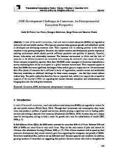
off-line programming. Current simulation systems do not typically have very high-fidelity sensor models, for example. Modeling the uncertainties and realistic responses of a sensor to different surface textures, geometries, and ambient conditions will be essential for designing and programming sensor-rich robotic workcells offline. Similarly, tactile sensors and hand kinematics must be well-modeled and well-calibrated to their physical counterparts. Hence, leveraging the advanced capabilities of next-generation robotic systems through offline programming raises the importance of accurate calibrations of a robot’s arm kinematics, sensors, and advanced hands. Collaborative Robots Robot collaboration (either with humans or with other robots) is often characterized by four levels of interaction [25]: independent, synchronous, simultaneous, and supportive. In independent collaboration, the robot and its collaborator operate on separate workpieces without any interaction. In synchronous collaboration, the robot and its collaborator operate on sequential components on the same workpiece. In simultaneous collaboration, the robot and its collaborator are co-located, and operate on separate tasks on the same workpiece(s) at the same time. And in supportive collaboration, the robot and its collaborator work ‘cooperatively’ to complete the processing of a single workpiece. Simultaneous and supportive tasks are expected to have the highest potential for risk of injury [26], so most state-of-the-art industrial operations requiring robot collaboration do so using synchronous interactions. In assembly tasks, for instance, multi-robot systems perform the component manipulations in a series of workstation operations rather than simultaneously to reduce risks to the robots, parts, and humans in the work environment. Specifically, one robot will perform its programmed task on the shared workpiece, and then that workpiece is passed to the next station for additional processing. Each robot is assigned a single task role, and parts are presented in fixtures. When multiple robots must operate simultaneously, the scheduling of the system is the principal concern for integrators [27]. Such scheduling includes resource allocations [2830], process distribution [29-32], logistical controls (i.e., part presentations [28, 33]), and collision avoidance [33]. In many of these test cases, the physical interaction between robots is restricted or nonexistent, and the robots operate simultaneously in the shared workcell, but in a non-supportive manner. Supportive collaborations require the threedimensional location and time-based coordination and synchronization of motions to minimize positioning and trajectory errors. Such errors may negatively impact the robots themselves, damage parts or tooling, or present hazards to human operators working in the area. Figure 2 shows an example of different robots collaborating. When programming robots in heterogeneous configurations (i.e., when the robots have separate, incompatible controllers), the robots’ joint- and Cartesian-space motions, data access, communication, and processing delays, and system processing timings must be characterized and registered to enable synchronization (see Figure 2 and Figure 3).
10
Figure 2: Illustrative Vignette of Two Heterogeneous Supportive Collaborating Robots. The red robot (left) is handing a part to the orange robot (right). Note that their geometries and capabilities are very different, yet they must have a common frame of reference about space and time to achieve this handoff.
A
B
C
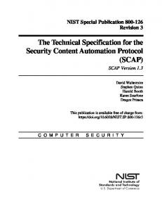
Figure 3: The synchronized timing of individual robots’ motion commands consists of the signal transit time, the command execution time, and the time necessary to move the robot (A). Traditional approaches for coordinating robots results in a serialization of motion commands (B), whereas timing the independent motions of robots can result in defined states being reached simultaneously (C).
11
Calibration Requirements and Techniques The field of robot and sensor calibration is both vast and long-lived, and as such we cannot provide an exhaustive survey of all possible calibration techniques. Instead, we will attempt to give a broad overview of many of the more common mechanisms for calibrating and registering robots and sensors, both as stand-alone platforms and as integrated systems. In general, a calibration process consists of four sequential steps: 1. Choosing a mathematic model 2. Taking lots of measurement data (this step implies a decision on the measurement device) 3. Calculating the appropriate control parameter errors to be minimized, and finally 4. Integrating the error compensation into the system. Calibrations can be time-consuming and can be performed at various levels of complexity. General challenges include: • Determining which measurements to take (location and number) to ensure good results while minimizing resources required • Deciding which metrology system or measurement approach to use for collecting the data • Deciding which algorithm and tools to use for processing the data, and • Knowing when the system is out of calibration. For example, for robot arm kinematics, depending on the type of error modeled, the calibration can be classified as Level-1 (only joints are modeled to determine the relationship between the signal to the joint and its actual joint displacement), Level-2 (entire kinematic calibrations – determine the basic kinematic geometry of the robot as well as the correct joint-angle relationship), and Level-3 (non-kinematic calibrations where errors in positioning of the end effector are due to non-geometric errors such as joint compliance, friction, and clearance, link compliance, stiffness, temperature, and dynamic modeling could be in this level too) [1, 34].
12
Figure 4: Conceptual View of the Different Coordinate Frames and Calibration/Registration Requirements
Figure 4 is a highly abstracted and idealized representation of a robot workcell with an articulated arm on a mobile base. The arm has a multi-fingered hand with tactile sensors and the cell includes two external sensors. To function correctly, all the different components must be calibrated and many must have the relationships between their coordinate frames established (“registered”). In the next sections, we will provide a brief summary of the calibration practices and issues for the main components in Figure 4.
Camera Calibration Computer vision techniques precisely calculate and mathematically represent a camera’s various property values -- both intrinsic and extrinsic. The extrinsic parameters define exactly where in the 3D space that a camera is located in the physical world (translation) and which way that the camera lens is pointing (rotation). The intrinsic parameters cover the camera model-specific attributes such as the camera’s focal length, lens distortion, etc. [35]. Knowing these properties then lets us determine how the camera’s reported image pixel values correspond to the real world (three-dimensional, 3D, space) that it is observing. The entire process poses many difficulties. As described in [36]:
13
“Complex robots can also pose many challenges for the calibration procedure. The robot may have many different sensors, and each sensor often has very different error characteristics. For instance, a laser rangefinder detects points in 3D very differently than a stereo camera, and a camera’s precision in resolving points is very dependent on its focal length. To complicate things further, if the camera is mounted on a robot arm or other actuated linkage, then the linkage’s error characteristics must also be incorporated into the sensor’s uncertainties.” Once these property values have been calculated, the correspondence between the camera’s image view (i.e., two dimensional – 2D – image space) and the real world (i.e., 3D Cartesian space) position can be mathematically represented.
Robot Calibration A succinct summary of robot calibration comes from Roth et al. [37]: “Calibration involves identifying a more accurate functional relationship between the joint transducer readings and the actual workspace position of the end effector and using these identified changes to permanently change (between each consecutive calibration) the robot positioning software.” Before a robot can plan a trajectory or perform any kind of motion, it must first understand its own configuration. Encoder or resolver information is meaningless unless there is a reference frame against which all subsequent readings can be compared. This mastering process involves manually moving the robot into an a priori established configuration, and recording the sensor readings. This is a registration process, where the robot’s joint/encoder readings are mapped to a known pose of the robot. This information is then used to establish a kinematic mapping of the totality of the joint values to a Cartesian coordinate frame at the robot’s origin. At this point, assuming the mastering process was performed correctly, the robot is calibrated only to itself. However, the robot is otherwise fully functional in that Cartesian motions to the robot’s tool flange can be commanded relative to that base frame. Programs can be written and executed without issue provided that the robot does not have to coordinate with another system (such as external sensors or other robots), or perform actions using an attached tool. Such actions require quality calibration of the robot, and then registering the robot to an external coordinate frame. Articulated Robot Calibration Ultimately, a robot must be precisely aware of its own position, and the position of all its constituent components, within its operating volume. This is the crux of robot calibration. A robot’s exact position, and its components’ positions, can be affected by a multitude of factors including machine wear, joint friction, and manufacturing imperfections [38, 39]. Robot calibration uses a combination of techniques to help compensate for any or all of these factors. That is, given a perfect robot calibration, a robot’s end effector will be positioned in Cartesian space with high accuracy and repeatability. The current techniques to achieve robot calibration involve procedures such as • Using precision measurement techniques to observe the differences between actual
14
robot position and the position the robot calculates it is at to observe repeatable and/or predictable translation and rotation errors, and • Modeling the capabilities of the robot in software and factoring in any known observable errors. Figure 5 illustrates some of the parameters, such as joint angles and link lengths, which must be factored into calibration procedures.
Figure 5: The more complex a robot, the more errors (joint offsets and link-length) that must be compensated.
Traditional calibration techniques vary in accuracy, ease of use, and cost to implement. Moreover, they share many of the following challenges [38]: • Trained personnel are needed to operate the measuring equipment properly. • Data collection is boring, time-consuming, and may be difficult to automate fully. • Some calibration techniques were developed for laboratory use, and are not intended for shop floors with uncontrolled environmental conditions. • The initial setup and measurement collection requires considerable human intervention, as most current technology does not enable dynamic self-calibration. In general, there are two different types of calibration commonly employed: 1) dynamics calibration, and 2) kinematics calibrations. Dynamics calibrations focus on the motions of the robot, and consist principally of computing the Jacobian matrix. The Jacobian matrix maps the velocities of the robot’s individual axes to the velocity of the robot’s tool as it moves through Cartesian space. This process is well documented in robotics textbooks (e.g., [40, 41]) for robot systems with known properties, and can otherwise be approximated if the robots’ characteristics are not well known (e.g., [42]). In contrast, kinematic calibrations are aimed at mapping the joint configuration to the position of the robot’s individual axes, links, and tools in Cartesian space. Typically kinematic calibrations are performed one axis at a time, making them lengthy to perform and cumbersome to analyze. While technology has advanced considerably since the dawn of robotics, many of the basic kinematic calibration techniques are still the same. The only distinction between legacy and modern methods is simply that current techniques employ modern and more advanced sensors and computer systems. The array of tools available,
15
though providing more options, may complicate the selection process for calibrations: Measurement devices [1] used for calibration include: 1. Touch probes with a reference artifact [44, 45] 2. Telescoping ball bar 3. Camera-based 3D (positioning) devices 4. Acoustic sensors 5. Large-range 3D measurement devices such as laser-trackers [46], coordinate measuring machines, theodolites [47], laser interferometry [35, 48, 49], and photogrammetry [50]. Each comes with its own advantages and disadvantages. Touch probe with reference artifact is one of the oldest methods and simplest to use; however, it is best used in a controlled environment and is not ideal for large volume systems. Telescoping ballbars use embedded sensors and analysis software to give a relatively simple, rapid check of positioning performance that is tied to international standards and are quite familiar to machine tool calibraters across the manufacturing floor; however, they are usually limited to approximately 300 mm in length and can only calibrate one-dimension at a time. Largerange 3D measurement devices provide extremely accurate, large volume measurements; however, the equipment is expensive, needs to be calibrated itself, and needs a trained operator to set up and use the device before calibrating the robot system. Rather having to calibrate each joint of the robot individually and then reference each one back to a common reference point, the robot’s end effector could be the only point calibrated. This may have its own advantage (shorter time period to calibrate) and disadvantage (the robot may not know its own volume space, i.e., how big it is!). Researchers are constantly trying to find easier and quicker ways to calibrate robots. For example, one group developed a 6D (complete pose, consisting of location and orientation) measurement system comprised of a camera-based system or a laser tracker with a 6D probe (e.g., telescoping ballbar system) [1]. By combining calibration techniques, they were able to accomplish the calibration in about an hour, at a relatively low cost. However, the system only has a small working volume of 300 mm and it does not factor in any sensors (e.g., vision, touch) that the user may want to use. The hunt is still on for the calibration methods that is easy to use, inexpensive, and quick enough to perform on a regular basis. A robot’s position is a combination of the requested location and the robot errors. The measurement device mentioned above will provide lots of data; however, it still does not necessarily provide a repeatable position response. The measurement data combined with an appropriate mathematical model (e.g., Denavit-Hartenberg and Denavit-Hartenberg Modified Conventions [43], Complete and Parametrically Continuous Model [44, 45], Product of Exponentials [46, 47]) will improve the representation of the position and orientation (i.e., the pose) of the robot end-effector. These mathematical models are a function of the robot joint angles and the error parameters that need to be modeled. Robot-Camera Calibration
Another method to approximate robot calibration is through observations of the robot’s workspace of specific target points using calibrated cameras. If the observational camera’s intrinsic and extrinsic properties can be calculated, then interpretation of objects in the camera’s view can be used to map out where objects are in the 3D space being observed.
16
Standard checkerboard patterns placed in the robot workspace can be used to calculate a camera’s specific intrinsic and extrinsic properties. An example of such a checkerboard is shown in Figure 6. A series of multi-image captures are collected of the checkerboard in various areas of the camera’s frame. These images are then used to calculate the values of the camera’s specific properties including: position, rotation, focal point, skew, and distortion properties. Once these properties are known, then the camera is considered to be a fully calibrated camera.
Figure 6: Checkboard patterns can be used to register multiple sensors at one time.
Two methods have been developed for determining a robot arm’s position and pose based on calibrated cameras: one method has the calibrated camera attached to the robot’s end effector to be able to calculate a precise view of where the camera is in 3D space and correspondingly where the robot’s end effector is in 3D space. The other method has the calibrated camera as a stationary camera (or stereo camera pairs) at the base of the robot observing the robot’s pieces as they move through the robot space [48-51]. Robot Calibration using Calibrated Cameras Generally speaking, there is a lack of a general-purpose framework for calibrating all of the sensors and actuators of a robot together that accounts for each sensor’s individual error characteristics. A promising new technique [36] allows the combination of data from a variety of observational sensors (laser range-finders, cameras, stereo cameras, etc.) in the robot’s workspace to be used along with the classic computer vision technique of bundle adjustment2 to solve the intrinsic and extrinsic properties along with error estimations of each individual sensor used. Once determined, these can be used together to get an accurate calculation of the robot’s position and pose. If these new techniques are proven to be consistently reliable and accurate and if straightforward methods and instructions can be created for robot manufacturers and/or SMEs to replicate these techniques, then all the advantages of having a precision robot calibration will be gained. One such attempt at accomplishing this is available for the ROS (Robot Operating System) environment. [52]
2 Bundle adjustment is a technique for deriving jointly optimal 3D structure and viewing parameter
(camera pose and/or calibration) estimates. “Bundle” refers to the group of light rays that emanate from each object feature and converge on the camera’s center.
17
Robot-Vehicle Calibration It is anticipated that robotic vehicles will be integral to the future of large-scale and flexible factory automation of assembly tasks. As noted above, automated guided vehicles (AGVs), mobile robots, and mobile manipulators (articulated robot arms mounted on mobile platforms [19]) are anticipated as being critical technologies for agile manufacturing applications, and ultimately pose the greatest risk in human-occupied factory environments. Ensuring that their position and sensor systems are correctly calibrated is essential. Many approaches exist for the calibration and evaluation of marker-less methods for localization, more commonly known as simultaneous localization and mapping (SLAM, [53, 54], discussed in more detail later). Within the manufacturing realm, however, SLAM does not provide localization robust enough to ensure optimal positioning performance or safety, but some results imply such performance may be eventually possible [55]. Other approaches use active mechanisms to project fiducials into the environment that are used for range measurement and localization (e.g., [56]). However, such methods have not found much application within industry. Instead, typical mobile platform installations focus on providing fixed references (e.g., visual targets or easily-identifiable structural components) within the environment to provide suitable localization and navigational support. Commercial options for such fiducials include retro-reflective markers [57], ceilingmounted bar codes [58], and wires, visual markers, or magnets embedded in the floor (e.g., [59]). Commercial AGV systems have known performance accuracies, though the performance of the mobile system is dependent on the extrinsic calibration between the tracking system and the robot itself. Typically, the AGV will have some form of onboard, odometry-based system that attempts to localize itself through dead reckoning. Odometry-based systems are dependent on accurate measurements of wheel radii, the baseline between wheels, wheel slip models, and the accuracy and precision of the steering mechanism (e.g., differential-steering versus Ackerman-steering). Gyro-based internal localization systems (e.g., inertial odometric navigation - ION) go through a series of known motions to calibrate the control laws. De Cecco [60], for instance, assumes the ION knows nothing about the AGV, and commands the AGV to move through a series of rounded rectangular paths to automatically generate estimates for the 1) steering angle at which the instantaneous center of rotation is at infinity, 2) the driving wheel radius, 3) the distance between the wheel rotation axes, and 4) the characteristics of the gyroscope itself. An infrared absolute triangulation system (with an angular uncertainty of ± 47 arcseconds and positional accuracy of ±2 mm) provided the inputs into the calibration procedure. As a verification metric, the calibration values for these characteristics were compared with the nominal values provided by the AGV and gyro vendors. In his experiment, this technique made it possible to achieve a mean difference in the end position estimation between the absolute system and the navigation algorithm of εx = 6 mm, εy = 4 mm, ε = 0.2 degrees. The variance achieved was σx=12 mm, σy = 8 mm, σ = 0.6 degrees over a path of 25 m long. Censi et al. [61] provide a mobile platform calibration technique for calibrating robot odometry as well as the extrinsic parameters for a laser-based localization system relative to its location on the robot. Unlike many other approaches, this method does not require the robot to move through known trajectories, though the authors do recommend δ
δ
18
trajectories be chosen that result in closed loops in confined spaces with relatively low speeds to maximize the sample density. Their evaluations were performed on a small, differentially-steered mobile robot with an onboard laser range finder, and the calibration verification was done by means of comparing the calibrated estimates with values measured manually (when possible) and provided in product specifications. Kelly and Sukhatme [62] solve the problem of extrinsically calibrating sensors to inertial measurement units onboard mobile robot platforms. Parameters recovered during the selfcalibration include sensor-to-sensor transformations, inertial measurement unit (IMU) biases, local gravity vector, and scene structure by utilizing structure from motion (i.e., SLAM). The approach was evaluated in simulation and in experiments. Verification took the form of comparing the self-calibration methodology with hand-measured results. Robot-Gripper/Hand Calibration A highly coveted functionality regarding multi-fingered, general purpose robotic hands is their ability to efficiently and effectively grasp objects within unstructured environments. Without accurate knowledge and control over the environment, perception and reactivity is of paramount necessity to robust interactivity. Neurophysiological research has repeatedly shown that humans possess a suite of finger-embedded mechanoreceptors that provide sensory information that is ultimately responsible for our ability to properly force modulate our grasps in the presence of uncertainty and disturbances [63, 64]. Consequently, many state-of-the art techniques in robotic grasping and manipulation exploit the feedback capabilities of many different kinds of finger sensors. For instance, contemporary strategies rely heavily on measuring contact forces [65-70]. Finger sensors can provide this information through sensory layouts such as load cells, barometers, accelerometers, electrodes, hydrophones, cameras, or some combination thereof. The complexity of these sensors with application to touch-related events not only lies with their design and integration, but also with their calibration. That is, inherently they are designed to respond to certain perturbations during contact, but their responses are made meaningful through the application of mathematical models. These models can be complex, and are typically applied offline on large reference datasets that have been collected. Furthermore, many of these sensors can exhibit nonlinear response dynamics that can complicate the calibration process. Generally speaking, the difficulty of the calibration process for these contact sensors rests with data collection and data analysis. The particular experience in each of these categories can vary significantly depending on the particular design and implementation of the sensor and its desired application.
19
Figure 7: Shows the attachment of a biomimetic fingertip as a contact sensor against a reference load cell for the data collection process for force calibration.
In the data collection process, raw sensory data from the touch sensor must be collected against a pre-calibrated reference. For force calibration, this stage is typically achieved by mounting the sensor directly to an external load cell as shown in Figure 7. This step is tedious in nature for many reasons. First, data collection is conducted on a per-sensor basis. Since general purpose robotic hands often possess many contact sensors, this process would have to be conducted for each one. Furthermore, particular care in properly exploring the sensor response range is necessary to ensure proper calibration. This includes sufficiently varying the points of application, contact direction, and force. Other complexities include proper temporal alignment of sensory output data to reference data, data trimming, and possibly filtering. In the data analysis process, a function needs to be created that establishes an accurate connection between the outputs of the contact sensor to external stimuli. The complexity of this process varies depending on the response dynamics of the contact sensor. For instance, load cell based sensors are well understood to be linear in nature, and ordinary linear regression can be applied to establish the mapping of strain gage voltages to forces. This method does not work for others such as electrodes in biomimetic sensors [71]. Instead, more complex filtering or machine learning algorithms such as artificial neural networks (ANN) need to be applied to the datasets to obtain proper calibration. Moreover, the particular internal parameters in these algorithms may need to be properly tuned to yield high-fidelity mapping performance. Depending on the sensor and particular mathematical model, a different function map may also need to be created for different data. For instance, data collected during interaction with objects of various hardness and curvatures. This process would also need to be repeated for each sensor on the robotic hand. Calibrating Robots to CAD Models for Offline Programming Fitting sensor data to CAD models for the identification and localization of parts has been demonstrated as an effective tool for industrial robot applications. While this is still an active field of research, the application of CAD models to workpiece identification and 20
localization is so effective that some consider their use to be a basic starting point for many offline programming industrial robots [72]. CAD models of the robots, themselves, have also gained popularity, and are often used as a basis for evaluating robot workcell design (e.g., [73]), process flow representation (e.g., [74]), and offline programming (e.g., [21]). Models of the robots are loaded into a 3D virtual representation of the actual or planned workcells. The kinematics of these models are linked to a simulated robot controller, allowing for the visualization of the robots’ motions as they would be executed by their real-world counterparts [75]. Such simulations of robot controllers (and the 3D rendered environments) are typically provided by the robot vendors, but third-party solutions are gaining in popularity for their ability to model robots and control algorithms from multiple sources. Another use of CAD models is for the evaluation of robot operational environments for safety and performance optimization. For instance, in 1992, Yao and Yusoff [76] demonstrated a system in which a material handling workcell for a 4-axis robot was registered to a commercial CAD representation of the operational space. This registration forms the basis of an error map that is used for task-oriented, collision-free trajectory planning for the robot whenever the environment is changed. Using the known kinematics of the robot, positional errors are projected throughout the modeled working environment. These error models provide the basis for offline planning, programming, and error-reduced performance optimization. Similar techniques are used today in open-sourced libraries for the offline, automatic generation of collision-free motion planning (e.g., [77]). Rather than representing environments in commercial software, robots and their operational environments are captured in the unified robot description format (URDF)[78] so as to be usable by ROS tools and libraries. In all of these examples, the calibration and registration of virtual robots, workpieces, and environments to the real world have been accomplished manually through meticulous measurement and verification processes. In the virtual-real transition, physical workcells are constructed from the original CAD models within some degree of construction tolerance, whereas the real-virtual transition is largely based on rough measurements of physical spaces integrated with vendor-provided 3D models of the robots. Advances in sensing, processing, and display capabilities have given rise to new applications with augmented reality. In such systems (e.g., [79]), calibrated markers are used to register the perspective of a vision system to the physical configuration, and a 3D rendered representation of the robot is projected into the operator’s visual display for programming and process feedback.
Calibrating Virtual Models to Sensor Data Vision sensor-based robot applications require some model of the parts on which the robots are operating. Such applications are historically limited to routine material handling (e.g., part acquisition and inspection), but advances in sensing and robot technologies are enabling expanded applications in the domains of robotic assembly, part manipulation, welding, and surface finishing. There are trade-offs between multiple factors, including flexibility, reliability, performance, cost, and ease-of-use depending on which sensors and models are used, however. For
21
example, limited-view model perspectives of the parts for monocular camera capture systems (e.g., parts being presented in matrix kit trays) compromise flexibility in favor of easier programming and increased reliability. In contrast, CAD-based model fitting of 3D point cloud data reduces the restriction on part presentation and grasping, and enables a broader range of intelligent applications due to the ability to directly map offline CAD data to online processes. Registering sensor information to virtual models (e.g., CAD data, as described previously) is a broad topic that is still actively being investigated. A full survey of such techniques is beyond the scope of this report, but it is worth mentioning some approaches from the literature landscape here. In particular, we will discuss techniques for template matching, feature matching, and cross-modal fitting. Template Matching Template matching is the most direct method for comparing virtual models to raw sensor inputs. Here, the virtual model consists of an a priori defined template (or specific instance or sub-samples of sensor data), which is provided to the observer system. The system then searches the sensor input for an exact match of that template to identify if and where that template occurs in the data stream. In image-based matching, for instance, an example image of an object or element is provided as a template. That template is then shifted across a query image to determine if and where that template image can be found. A common implementation of this matching process is by means of correlation coefficients (or measures of similarity) between the archetype template and the raw sensor input. A limitation of the template matching approach, however, is that templates must be defined for every possible instance and orientation of the components to be identified. Certain transforms may be applied to the templates (e.g., in image-based matching, templates may be scaled, skewed, or rotated) to identify the approximate offsets from the base template. Template matching is best applied when the presentation and tolerances of parts can be tightly controlled. Such matching processes are generally not robust against large deviations from the archetype templates (e.g., part variations or shifts in lighting in imagebased matching). Moreover, increasing the search space, number of comparison templates, or transforms applied to the templates increases the computational cost of identification and localization. Certain performance optimization tricks such as subsampling [80] or signal scaling can be used to mitigate high computational costs. Feature Matching In contrast with template matching, which requires a representative sample for comparison, feature matching provides identification and localization based on collections of numerical rules (or classifiers). Here, these classifiers act as virtual models, and provide the basis of assessing sensor inputs. Specific sub-elements of the inputs are uniquely identified based on mathematically identifiable aspects of the sensor space. Such aspects include identified edges or circles in camera images [81], force and torque profiles in force-based control measurements [82], and specific frequency and magnitude profiles in sound-based applications [83]. Multiple classifiers may be used to improve identification and localization by means of inter-classifier relationships. The matching process consists largely of a goodness of fit metric, where the mathematical features, once identified and located within the inputs data stream, are assessed based on the defined inter-classifier relationships. Such assessments may be based on root mean 22
errors (differences) between the measured values, or in terms of transformation magnitudes necessary to fit the classifiers to the data stream (e.g., comparing relationships based on attributes, such as using pattern recognition algorithms like the K-nearest neighbors techniques[84]). Earlier we introduced a related field of study, simultaneous localization and mapping, or SLAM. As the name implies, SLAM attempts to identify where within a parameter space a given system is located, while simultaneously characterizing that space. This is most commonly applied toward the mobile robot domain, with specific applications in robot navigation and planning ([53, 54]). Both SLAM and SLAM-based navigation are extensive fields of research, but the underlying principle is as follows. A robot-mounted sensor system measures the distance between the robot and some identified features (or landmarks) in the surrounding area. These features must be both easily identifiable (e.g., flat surfaces or corners) and static. Based on these distance measurements, the robot estimates its position relative to these features based on prior estimates of previously seen (and recorded) features. These position estimates may be combined with dead reckoning state estimates based on wheel encoders or open-loop control predictions. As the robot moves throughout the space, both its position and the map of identified features are refined. If the robot traverses through that space again, the generated maps may be used to provide localization cues (e.g., through Monte Carlo processes [85]). In general, the SLAM process is largely open loop, as the true locations of the robot and identified features are never known or measured. In general, feature-based matching algorithms are both fast and robust. However, accuracy may be impacted if bounds are not properly placed on the quality of feature matches, or if the initial set of features is poorly defined. Specifically, in contrast with template matching, the process of mathematically defining features and their weights is not always intuitive. What appear to be key features for a human to identify parts may not work as well for an automated system. As such, a considerable amount of initial trial and error may be required. Similarly, if the system is required to go open-loop as in SLAM, even minor matching errors may accumulate to produce larger, irrecoverable errors downstream unless concerted efforts are made to “close the loop” using established reference points. Cross-Modal Fitting In both template and feature matching, virtual models are defined within the context of the constituent data streams. There is, however, a significant challenge presented when the virtual model is defined in a configuration space that is not identical to the raw sensor input. In such instances, one representation must be transformed into the format of the other, or both must be transformed into a third space for direct comparison. An illustrative example of such cross-modal fitting is attempting to match a CAD model to raw red-green-blue-depth (RGBD) data. In such cases, both the CAD model and the RGBD data must be projected into the Cartesian coordinate space. The RGBD data will take the form of a point cloud, while the CAD model will be a geometric solid. The brute-force approach exhaustively rotates and shifts both the point cloud and the solid until the best possible fit is found. If allowed, such an approach could take an eternity to complete if the accuracy requirements are too stringent. An alternative approach is to project both the CAD model and the RGBD point cloud into yet another form (e.g., shape proxies [86]) that enable faster and more direct comparisons. Other examples of this include converting the CAD model into a point cloud for K-nearest neighbor evaluation, or the inverse in which a CAD
23
model is generated from point cloud data (i.e., “reverse engineering” [87]). This transformative process involves some level of initial computational overhead, but significantly reduces the problem complexity. Essentially, the cross-modal problem becomes reduced to either a template or a feature matching problem.
Discussion In this report, we introduced challenges to integrating robots into manufacturing processes faced by SMEs as well as large manufacturers. We drew specific attention to the issues concerning robot system calibration and registration, and presented a number of approaches from the literature to address many of the calibration and registration challenges. Clearly, calibration and registration issues are but a small fraction of the barriers to small- and medium-sized enterprises accepting robot technologies. However, these issues are central to the performance of any robot integrated into a manufacturing process. Being aware of both the nature of the challenges and the existence of approaches to addressing those challenges is critical to acceptance. The processes of calibrating and registering robots to other systems are difficult and time consuming. As the needs and concerns of SMEs become well documented and understood, new, user-friendly tools are expected to become available to utilize calibration and registration techniques with minimal effort. This endeavor, however, cannot be completed in a vacuum, or without the active participation of SMEs. New standards may be written to address the requirements for providing assurance of system performance. But without the inputs of SMEs, these standards are unlikely to address the broad spectrum of stakeholder preferences. Similarly, new technologies and tools may be developed to ease the intellectual burden of calibration and registration. Yet, if SMEs are either unaware of their existence or unwilling to provide feedback on experimental systems, these technologies are unlikely to find their way onto the manufacturers’ shop floors. Therefore, a convening of all the interested parties is needed to achieve progress in the adoption of robotics by SMEs. This report is intended to serve as a starting point for the discussions and formulation of action plans leading towards the development of accurate and easy to implement toolkits for reducing the burden of calibration and registering of robotic workcells.
24
Bibliography 1. 2.
3.
4. 5. 6. 7. 8. 9. 10. 11. 12. 13. 14. 15. 16. 17. 18. 19.
Nubiola, A. and I.A. Bonev, Absolute robot calibration with a single telescoping ballbar. Precision Engineering, 2014. 38: p. 472-480. Computing Community Consortium, Workshop on Opportunities in Robotics, Automation, and Computer Science. 2014: http://www.cra.org/ccc/files/docs/meetings/NSF-OSTP-CCC-RVO-WorkshopReport-Oct21-2013.pdf. Marvel, J.A., Collaborative Robotics: A Gateway into Factory Automation, in ThomasNet News. 2014: http://news.thomasnet.com/IMT/2014/09/03/collaborative-robots-a-gatewayinto-factory-automation/. Lavars, N., Factory-in-a-Day project aims to deploy work-ready robots within 24 hours, in Gizmag. 2014: http://www.gizmag.com/factory-in-a-day/30053/. Union, E. Factory-in-a-Day. 2013 23 September, 2014]; Available from: http://www.factory-in-a-day.eu/ Barajas, L.G., A.L. Thomaz, and H.I. Christensen. Ushering in the Next Generation of Factory Robotics & Automation. in National Workshop on Challenge to Innovation in Advanced Manufacturing: Industry Drivers and R&D Needs. 2009. International Federation of Robotics. Statistics - IFR International Federation of Robotics. 2014 [cited 2014; Available from: http://www.ifr.org/industrialrobots/statistics/. Knight, W., Increasingly, robots of all sizes are human workmates, in MIT Technology Review. 2014. Orcutt, M. Manufacturers Adding Robots to the Factory Floor in Record Numbers. 2014 [cited 2015 03 February]; Available from: http://www.technologyreview.com/graphiti/529971/robots-rising/. Whitney, D.E., Mechanical assemblies: their design, manufacture, and role in product development. Vol. 1. 2004: Oxford University Press. Shneier, M., et al., Measuring and Representing the Performance of Manufacturing Assembly Robots. 2015, National Institute of Standards and Technology: Gaithersburg, MD. Dafle, N.C., et al. Extrinsic dexterity: In-hand manipulation with external forces. in Robotics and Automation (ICRA), 2014 IEEE International Conference on. 2014. IEEE. Computing Community Consortium, A roadmap for US robotics: From Internet to robotics. 2013: http://www.us-robotics.us/reports/CCC Report.pdf. Okamura, A.M., N. Smaby, and M.R. Cutkosky, An overview of dexterous manipulation, in IEEE International Conference on Robotics and Automation. 2000: San Francisco, CA, USA. p. 255-262. Falco, J., J. Marvel, and E. Messina, Dexterous Manipulation for Manufacturing Applications Workshop, N.I.o.S.a. Technology, Editor. 2013: http://www.nist.gov/el/isd/upload/NIST-IR-7940.pdf. Gray, T., D. Orf, and G. Adams, Mobile Automated Robotic Drilling, Inspection, and Fastening. 2013, SAE Technical Paper. Li, X., et al. Automatic offline program calibration in robotic cells. in Cyber Technology in Automation, Control, and Intelligent Systems (CYBER), 2014 IEEE 4th Annual International Conference on. 2014. IEEE. Lewis, J., Elements of Successful Vision-Guided Robotics, in Assembly. 2013. Marvel, J.A. and R. Bostelman, Towards mobile manipulator safety standards, in IEEE International Symposium on Robotic and Sensors Environments. 2013: Washington 25
20. 21. 22. 23. 24. 25. 26. 27. 28. 29. 30. 31. 32. 33. 34. 35. 36. 37. 38. 39. 40.
D.C. p. 31-36. Chen, H., T. Fuhlbrigge, and X. Li, A review of CAD‐based robot path planning for spray painting. Industrial Robot: An International Journal, 2009. 36(1): p. 45-50. Neto, P., J.N. Pires, and A.P. Moreira, CAD-based off-line robot programming, in IEEE Conference on Robotics Automation and Mechatronics (RAM). 2010. p. 516-521. da Motta, J.M.S., C.A.G. de Sousa, and F.A. Afonso. An off-line robot programming system including workcell and robot calibration. in ABCM Symposium Series in Mechatronics. 2004. Bergström, G., Method for calibrating of off-line generated robot program, in Department of Automatic Control. 2011, Chalmers University of Technology. Dynalog. Integrated OLP process at JCI using DynaCal. [cited 2015 January 6, 2015]; Available from: http://www.dynalog-us.com/dynalogmainsite_005.htm. Helms, E., R.D. Schraft, and M. Hägele, rob@work: Robot assistant in industrial environments, in 11th IEEE International Workshop on Robot and Human Interactive Communication. 2002: Berlin, Germany. p. 399-404. Marvel, J.A., J. Falco, and I. Marstio, Characterizing task-based human-robot collaboration safety in manufacturing. IEEE Transactions on Systems Science and Cybernetics: Systems, 2015. 45(2): p. 260-275. Abd, K., K. Abdhary, and R. Marian, A scheduling framework for robotic flexible assembly cells. King Mongkut's University of Technology North Bangkok: International Journal of Applied Science and Technology, 2011. 4(1): p. 31-38. Nof, S.Y. and Z. Drezner, The multiple-robot assembly plan problem. Journal of Intelligent and Robotic Systems, 1993. 5: p. 57-71. Hsieh, S.-F., Re-configurable dual-robot assembly system design, development and future directions. Industrial Robot: An International Journal, 2003. 30(3): p. 250-257. Fu, L.-C. and Y.-J. Hsu, Fully automated two-robot assembly cell, in IEEE International Conference on Robotics and Automation. 1993: Atlanta, GA USA. p. 332-338. Glibert, P.-R., et al., Scheduling of a multi-robot assembly cell. Computer Integrated Manufacturing Systems, 1990. 3(4): p. 236-245. Lee, J.-K. and T.-E. Lee, Automata-based supervisory control logic design for a multirobot assembly cell. International Journal of Computer Integrated Manufacturing, 2010. 15(4): p. 319-334. Bonert, M., L.H. Shu, and B. Benhabib, Motion planning for multi-robot assembly systems. International Journal of Computer Integrated Manufacturing, 2010. 13(4): p. 301-310. Mooring, B.W., Z.S. Roth, and M.R. Driels, Fundamentals of Manipulator Calibration. 1991: John Wiley & Sons, Inc. Tsai, T.-M., Camera Calibration for a Manufacturing Inspection Workstation. 2005, US Department of Commerce, Technology Administration, National Institute of Standards and Technology. Pradeep, V., K. Konolige, and E. Berger. Calibrating a multi-arm multi-sensor robot: A bundle adjustment approach. in Experimental Robotics. 2014. Springer. Roth, Z.S., B. Mooring, and B. Ravani, An overview of robot calibration. Robotics and Automation, IEEE Journal of, 1987. 3(5): p. 377-385. Elatta, A.Y., et al., An Overview of Robot Calibration. Information Technology Journal, 2004. 3(1): p. 74-78. Roth, Z.S., B.W. Mooring, and B. Ravani, An overview of robot calibration. IEEE Journal of Robotics and Automation, 1987. 3(5): p. 377-385. Jazar, R.N., Theory of Applied Robotics: Kinematics, Dynamics, and Control. 2nd ed. 2010: Springer Science+Business Media.
26
41. 42. 43. 44. 45. 46. 47. 48. 49. 50. 51. 52. 53. 54. 55.
56. 57. 58.
59. 60.
Kafrissen, E. and M. Stephens, Industrial Robots and Robotics. 1984, Reston, Virginia: Reston Publishing Company, Inc. Piepmeier, J.A., G.V. McMurray, and H. Lipkin, A dynamic Jacobian estimation method for uncalibrated visual servoing, in IEEE/ASME International Conference on Advanced Intelligent Mechatronics. 1999: Atlanta, GA, USA. p. 944-949. Wikipedia. Hartenberg Parameters. 2014 24 September, 2014]; Available from: http://en.wikipedia.org/wiki/Denavit%E2%80%93Hartenberg_parameters. Zhuang, H., Z.S. Roth, and F. Hamano, A complete and parametrically continuous kinematic model for robot manipulators. IEEE Transactions on Robotics and Automation, 1992. 8(4): p. 451-463. Zhuang, H. and Z.S. Roth, Robot calibration using the CPC error model. Robotics and Computer-Integrated Manufacturing, 1992. 9(3): p. 227–237. Brocket, R.W., Robotic manipulators and the product of exponentials formula, in In Lecture Notes in Control and Information Sciences: Mathematical Theory of Networks and Systems. 1984. p. 120-129. Tao, P.Y., et al., Product-Of-Exponential (POE) Model for Kinematic Calibration of Robots with Joint Compliance, in IEEE/ASME International Conference on Advanced Intelligent Mechatronics. 2012. p. 496-501. Augustson, T.M., Vision Based In-Situ Calibration of Robots: with Application in Subsea Interventions, in Mechanical Engineering Department. 2007, Pontificia Universidade Catolica do Rio de Janeiro: Lap Lambert Academic Publishing. Du, G. and P. Zhang, Online robot calibration based on vision measurement. Robotics and Computer-Integrated Manufacturing, 2013. 29(6): p. 484-492. Meng, Y. and H. Zhuang, Autonomous robot calibration using vision technology. Robotics and Computer-Integrated Manufacturing, 2007. 23(4): p. 436-446. Motta, J.M.c.S.T., G.C.d. Carvalho, and R.S. McMaster, Robot calibration using a 3D vision-based measurement system with a single camera. Robotics and ComputerIntegrated Manufacturing, 2001. 17(6): p. 487-497. ROS. ROS (Robot Operating System)-Industrial’s Multi-Camera Extrinsic Calibration with a Target package. [cited 2015 May 6]; Available from: http://wiki.ros.org/industrial_extrinsic_cal/Tutorials/Multi_camera_calibration. Durrant-Whyte, H. and T. Bailey, Simultaneous localization and mapping: Part I, in IEEE Robotics and Automation Magazine. 2006. p. 99-110. Bailey, T. and H. Durrant-Whyte, Simultaneous localization and mapping (SLAM): Part II, in IEEE Robotics and Automation Magazine. 2006. p. 108-117. Wang, C.-C., C. Thorpe, and S. Thrun, Online simultaneous localization and mapping with detection and tracking of moving objects: THeory and results from a ground vehicle in crowded urban areas, in IEEE International Conference on Robotics and Automation. 2003: Taipei, Taiwan. p. 842-849. Reid, I.D., Projective calibration of a laser-stripe range finder. Image and Vision Computing, 1996. 14(9): p. 659-666. Götting KG. Laser Scanner for Navigation. 2014 [cited 2014 1 October]; Available from: http://www.goetting-agv.com/components/43600. TotalTrax, I. The Sky-Trax System. 2014 [cited 2014 1 October]; Information page for the Sky-Trax forklift localization system. Includes a few case studies (PDFs) at the bottom of the page.]. Available from: http://totaltraxinc.com/index.php/smartforklift-solutions/forklift-tracking/sky-trax. Götting KG. Introduction Inductive Track Guidance. 2014 [cited 2014 1 October]; Available from: http://www.goetting-agv.com/components/inductive/introduction. De Cecco, M.D., Self-calibration of AGV inertial-odometric navigation using absolute-
27
61. 62. 63. 64. 65. 66. 67. 68. 69. 70. 71. 72. 73. 74. 75. 76. 77. 78. 79. 80.
reference measurements, in IEEE Instrumentation and Measurement Technology Conference. 2002: Anchorage, AK, USA. p. 1513-1518. Censi, A., et al., Simultaneous calibration of odometry and sensor parameters for mobile robots. IEEE Transactions on Robotics, 2013. 29(2): p. 475-492. Kelly, J. and G.S. Sukhatme, Visual-intertial sensor fusion: Localization, mapping and sensor-to-sensor self-calibration. International Journal of Robotics Research, 2011. 30(1): p. 56-79. Johansson, R.S. and R. Flanagan, Coding and use of tactile signals from the fingertips in object manipulation tasks. Nature Review Neuroscience, 2009. 10: p. 245-259. Johansson, R.S., C. Häger, and R. Riso, Somatosensory control of precision grip during unpredictable pulling loads. Experimental Brain Research, 1992. 89: p. 192-203. Glossas, N.I. and N.A. Aspragathos, Fuzzy logic grasp control using tactile sensors. Mechatronics, 2001. 11(7): p. 899-920. Sadigh, M.J. and H. Ahmadi, Robust control algorithm for safe grasping based on force sensing, in IEEE International Conference on Robotics and Biomimetics. 2008: Bangkok, Thailand. p. 1279-1284. Ascari, L., et al., Bio-inspired grasp control in a robotic hand with massive sensorial input. Biological Cybernetics, 2009. 100(2): p. 109-128. Sadigh, M.J. and H. Ahmadi, Safe grasping with multi-link fingers based on force sensing, in IEEE International Conference on Robotics and Biomimetics. 2009, 17961802: Guilin, China. Romano, J.M., et al., Human-inspired robotic grasp control with tactile sensing. IEEE Transactions on Robotics, 2011. 27(6): p. 1067-1079. Boughdiri, R., et al., Dynamic modeling and control of a multi-fingered robot hand for grasping task, in International Symposium on Robotics and Intelligent Sensors. 2012. p. 923-931. Wettels, N. and G.E. Loeb, Haptic feature extraction from a biomimetic tactile sensor: Force, contactor location and curvature, in IEEE International Conference on Robotics and Biomimetics. 2011: Phuket, Thailand. p. 2471-2478. Pan, Z., et al., Recent progress on programming methods for industrial robots. Robotics and Computer Integrated Manufacturing, 2012. 28: p. 87-94. Adam, G.K. and E. Grant, QMTOOL - A qualitative modelling and simulation CAD system for designing automated workcells, in IEEE International Conference on Robotics and Automation. 1994: San Diego, CA. p. 1141-1146. Jongeling, R. and T. Olofsson, A method for planning of work-flow by combined use of location-based scheduling and 4D CAD. Automation in Construction, 2007. 16(2): p. 189-198. Harrison, W.S., Virtual Fusion: The Integration and Analysis of Simulation and Real Processes for Manufacturing Process Deployment, in Mechanical Engineering. 2011, University of Michigan. Yao, Y.L. and M.R.M. Yusoff, A CAD-based mapping and layout facility for precision robotic operations. Robotics and Computer Integrated Manufacturing, 1992. 9(6): p. 505-511. Chitta, S., I. Sucan, and S. Cousins, MoveIt! [ROS Topics], in IEEE Robotics and Automation Magazine. 2012. p. 18-19. Meüssen, W., J. Hsu, and R. Diankov. URDF - Unified Robot Description Format. 2014 [cited 2015 3 February]; Available from: http://www.ros.org/wiki/urdf. Girbacia, F., M. Duguleana, and A. Stavar, Off-line programming of industrial robots using co-located environments. Advanced Materials Research, 2012: p. 1654-1657. Vanderbrug, G.J. and A. Rosenfeld, Two-stage template matching. IEEE Transactions
28
81. 82. 83. 84. 85. 86. 87.
on Computers, 1977. c-26(4): p. 384-393. Forsyth, D.A. and J. Ponce, Computer Vision: A Modern Approach. 2003, Upper Saddle River, New Jersey, USA: Prentice Hall. Skubic, M. and R.A. Volz, Acquiring robust, force-based assembly skills from human demonstration. IEEE Transactions on Robotics and Automation, 2000. 16(6): p. 772781. Kashino, K., T. Kurozumi, and H. Murase, A quick search method for audio and video signals based on histogram pruning. IEEE Transactions on Multimedia, 2003. 5(3): p. 348-357. Peterson, L.E., K-nearest neighbor. Scholarpedia, 2009. 4(2): p. 1883. Thrun, S., et al., Robust Monte Carlo localization for mobile robots. Artificial Intelligence, 2001. 128: p. 99-141. Schnabel, R., R. Wahl, and R. Klein, Efficient RANSAC for point-cloud shape detection. Computer Graphics Forum, 2007. 26(2): p. 214-226. Durupt, A., et al., From a 3D point cloud to an engineering CAD model: a knowledgeproduct-based approach for reverse engineering. Virtual and Physical Prototyping, 2008. 3(2): p. 51-59.
29