Toplogy Based Modeling and Simulation of UMTS-WLAN Wireless Heterogeneous Network Dina S. Deif
Hesham El-Badawy
Electronics and Communications Dept. Misr International University Cairo, Egypt
[email protected]
Network Planning Dept. National Telecom Institute Cairo, Egypt
[email protected]
Hadya El-Hennawy Dean of Faculty of Engineering Ain Shams University Cairo, Egypt
[email protected]
Abstract— Wireless Heterogeneous Networks (WHN) have become one of the deployment scenarios for the Fourth Generation Mobile Communications Networks (4G). In recent trends, heterogeneous service models integrating between Wireless LANs (WLANs) and cellular networks have attracted the most attention. This is due to the increasing demand for broadband services, causing cellular network providers to consider the complementary use of WLAN in hot spot areas and indoor locations in a cooperative context. Cooperative approaches in integration are characterized by mutual investments and/or ownership of both access technologies, opening up the possibilities for centralized coordination between them to optimize the design parameters and hence the performance of the integrated network. In this paper, we propose an architecture for deploying a service model combining UMTS and WLAN hotspots into an integrated cooperative heterogeneous network. Through modeling and simulation, we investigate the effect of certain network topology parameters on the over-all network performance. We present a WLAN-first based vertical handoff (VHO) scheme to use in our proposed model. Simulation results show that the topology parameters of the integrated network, specifically the positioning of the WLAN hotspots, can be used as design variables to enhance the overall network performance through minimizing call blocking probability.
Keywords-Heterogenous networks; WLAN; UMTS; Vertical handoff; Topology; Modeling; Simulation
I.
INTRODUCTION
Wireless Heterogeneous Networks (WHN) have become one of the deployment scenarios for the Fourth Generation Mobile Communications Networks (4G). Operators and service providers can build new service models by combining different radio access technologies (RATs), often having overlapping areas of coverage, such as IEEE 802.11 Wireless Local Area Networks (WLANs), GPRS/EDGE, cdma2000, and WCDMA,
978-1-4244-7202-4/10/$26.00 ©2010 IEEE
aiming to enhance the integrated wireless networks performance, in terms of coverage and quality of service (QoS). A mobile node (MN) equipped with a multi-interface terminal should be able to roam among these heterogeneous networks by seamlessly switching between the serving access nodes through both horizontal handoffs (HHOs) and vertical handoffs (VHOs), benefiting from the diverse characteristics of the constituting access technologies. In recent trends, the service models integrating between WLANs and cellular networks have attracted the most attention. This is due to the fact that both access technologies already coexist, have complementary characteristics and many cellular devices have dual RF interfaces for WLAN and cellular access. Furthermore, the increasing demand for broadband services caused cellular network providers to consider the complementary use of WLAN in hotspots and indoor locations in a cooperative context, hence enhancing the service package offered to subscribers and offloading data traffic from the cellular frequency bands [1]. One of the main challenges in deploying such a heterogeneous network is the vertical handoff management [2]. The term collectively refers to the three main steps of the vertical handoff process: system discovery, handoff decision and handoff execution. The handoff decision (also referred to as network selection), being the most important step in the vertical handoff process, received greater emphasis in literature. A common and natural trend for vertical handoff in WLAN/WWAN integrated networks is the WLAN-first scheme, where WLANs are always preferred by mobile nodes whenever the WLAN access is available, to possibly increase bandwidth and reduce cost compared to WWANs [3]. Numerous variations and enhancements on this vertical handoff scheme appeared in literature. In [4], WLAN-first scheme is adopted, where the VHO decision is taken through a fuzzy logic-based algorithm, taking into account radio signal strength (RSS), and threshold and hysteresis values. In [5], a
dwell timer is added to a WLAN-first based vertical handoff scheme to minimize service quality degradations such as decreased throughput and network disconnection. In this paper, we present an architecture that integrates UMTS, as the cellular access technology, and WLAN into an integrated cooperative wireless heterogeneous network. We investigate the effect of different parameters in the topology of the proposed integrated network architecture, specifically the positioning of the WLAN hotspots, on the overall call blocking probability. Modeling and simulation are used to illustrate these effects, and find the optimum positioning parameters for the deployment of the WLAN hotspots in the integrated network coverage area. In our proposed model, we adopt a WLAN-first based VHO decision algorithm that employs the actual radio signal strength values, signal thresholds and available radio resources in both access networks as decision inputs. The rest of this paper is organized as follows. The model description of the proposed integrated network architecture is presented in section II. In section III, the WLAN-first based vertical handoff algorithm used in our proposed model is described. Simulation results are shown and discussed in IV. The paper is concluded in V.
II.
MODEL DESCRIPTION
Currently, the deployment scenarios for WHNs can be classified into competitive or cooperative scenarios. In the competitive scenario, diverse access technologies are operated by different network providers (NP), and it’s impractical to deploy any centralized entities to coordinate the operations, such as radio resource management. On the other hand, the cooperative scenario is characterized by mutual investments and/or ownership of different access technologies, opening up the possibilities for centralized coordination between them to optimize the design and performance of the integrated heterogeneous network, particularly through joint radio resource management (JRRM). This is consistent with the work published in [6-9]. In this paper, we adopt a cooperative approach, assuming a single network operator for both constituting access technologies. On the other hand, there are three strategies for handoff decision mechanisms: mobile-controlled handoff (MCHO), network-controlled handoff (NCHO), and mobile-assisted handoff (MAHO) [2]. From the perspective of the adopted cooperative approach for integration, MAHO is the most suitable. This is due to the fact that a dual-interface MN can easily perform RSS measurements when roaming in a WHN, using the reference channel/beacon of the different access networks. These measurements, along with user preferences and service requests, are employed as decision inputs to a VHO decision algorithm, implemented in a central networkcontrolled mobility-management entity. Inspired by the work published in [6], we use the name vertical handoff decision controller (VHDC) for this entity. VHDC utilizes the media independent handover function (MIHF) in the IEEE 802.21 standard, to enable the exchange of the integrated network’s conditions and available RRs, through standards-based
messages between itself and both types of access networks (APs and Node B). The following subsections provide a detailed description of the different parts in our proposed UMTS-WLAN heterogeneous network model. A. UMTS Node B UMTS cells are deployed in a pattern of 7 cells, with a hexagonal pattern used for cell shapes, providing a suitable coverage of the circular radiation patterns of Node Bs’ antennas. Each UMTS cell is assumed to be served by one antenna, positioned in the center of the circular coverage area, with a radius Ru . In order to investigate the impact of the integration between the UMTS cell and the WLAN hotspots inside it on the integrated network performance, only the center Node B, located at (0 ,0 ) coordinates, is considered in calculations, and will be referred to as the origin Node B. The situation of the other neighboring UMTS cells will not be taken into consideration. Consequently, VHOs between the center Node B and the hotspots’ APs are considered, and no HHOs to/from neighboring UMTS cells are taken into consideration. Node B will allocate its limited RRs to the MNs attached to it at any instant in time, according to the decisions issued by the VHO decision algorithm implemented in the VHDC.
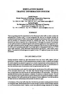
B. WLAN APs It is common that several APs are implemented within a single cellular cell coverage area, where the BS(s) provide almost full coverage of the integrated network, and APs represent hotspots with much smaller coverage areas. In our proposed architecture, four WLAN IEEE 802.11 hotspots are implemented inside the UMTS cell. Each hotspot is serviced by an AP with an omni directional antenna positioned also in the center of its circular coverage area. The APs positions are defined by their polar coordinates referenced to the system’s origin (0 ,0 ) , denoted D APi ,θ APi , with a coverage of radius Rwi ,
(
)
where 1 ≤ i ≤ 4 .All APs are assumed to have the same size, with radii equal to Rw .We assumed that the angular spacings between the four APs are equal and the radial coordinate of all four is equal to D AP . Therefore, the four APs form a tier inside the UMTS cell as depicted in Fig.1.
C. Mobile Nodes (MN) The population of mobile nodes is generated in the simulation software with three parameters; the polar coordinates of the MN referenced to the origin (0 ,0 ) , denoted r j , θ j , defining the spatial position of each MN in the coverage area under test, and the requested data rate of the MN, which corresponds to the service type the MN is using (voice or any data application). The number of MNs generated in each simulation scenario is denoted N , where 1 ≤ j ≤ N . MNs are distributed using two different population schemes. The first scheme uses a random distribution for both radial and angular coordinates r j and θ j . The second scheme uses a normal
(
)
distribution for the radial coordinate r j , and a random
TABLE I.
NETWORK PARAMETERS USED IN SIMULATION
Parameters
Values UMTS Parameters
Cell radius
1000 m
Node B transmit power
45 dBm
Bandwidth capacity Threshold
12 Mbps
ζu
-119 dBm
Node B antenna height
25 m
WLAN Parameters
WLAN range
50 -150 m
RF band
ISM 2.4 GHz
AP transmit power
1mW - 40 mW
Bandwidth capacity
Figure 1. WLAN-UMTS heterogeneous network topology
AP sensitivity
distribution for the angular coordinate θ j , which is a more realistic distribution. Only data services are considered in simulation and, the requested data rate of all MNs is assumed to be a constant of 64 Kbps.
D. Path Loss Models The adopted propagation model for the UMTS cell in this simulation is the COST 231 (Walfisch-Ikegami) NLOS model, given by (1) [10] LuNLOS [ dB ] = LFS + Lrts + LMSD
(1)
Where LFS is the free space loss, Lrts is the roof-to-street loss, and LMSD is the multi-diffraction loss. For the WLAN hotspots, path loss model used inside each hotspot in the simulation is assumed to be the dual slope model, given by (2) [11]
Lw [ dB ] = Lref + 10 n1 log10 ( ri , j ) + 10( n2 − n1 ) log10 ( 1 + ri , j / rb ) (2)
Where ri , j is the distance between MNj and APi, Lref is the reference path loss at ri , j = 1 m, taken to be equal 40 dB , n1 and n2 are the path loss exponents before and after the breakpoint distance rb , and are taken to be equal to 2 and 4 respectively. The rest of the parameters used in (1) and (2) in the simulation are shown in Table I.
ζw
2 Mbps -80 dBm
AP antenna height
1.5 m
Breakpoint distance rb
72 m MN Parameters
MN required data rate
64 kbps
Average MN height
1.5 m
Number of MNs
240
III.
VERTICAL HANDOFF DECISION ALGORITHM
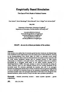
It is assumed that the VHDC maintains a list of all candidate service nodes available in its coverage area; in this case these can either be a Node B or one or more of the four APs. The VHDC also collects information on the load status of every AP and Node B on its list via the MIHF. Hence, available radio resources in the candidate service nodes are assumed to be obtainable information in the VHDC, and are used as inputs to the decision algorithm. Furthermore, it maintains a periodically updated service matrix, which depicts the current service node of each MN in the integrated network coverage area after each decision instant. Since direct comparison of RSS values from different access technologies can not be employed, two different thresholds are used, denoted ζ w and ζ u . We take ζ w to be equal to the AP sensitivity and ζ u to be equal to the sensitivity level required for circuit switched 64 kbps data service in UMTS cell. APs are the favored service nodes whenever available. However, sufficient radio resources must be available in the AP in question at the decision instant for a VHO or a new call request to be granted, or else Node B remains the node of service. On the other hand, handoff /new call blocking of a MN can occur in any of the following three cases, as depicted in Fig.2:
a) The current service node is Node B, but its RSS dropped below ζ u and the MN is not in the coverage of any of the APs. b) The current service node is an AP, but its RSS dropped below ζ w , and RRs of Node B are already consumed.
Hence, we present a comparison between our proposed integrated network topology at optimum D AP and Rw / Ru values, and the previously published results in [9].
Figure 2. Flowchart of VHO decision algorithm
c) The current service node is an AP, but its RSS dropped below ζ w , however, RSS of Node B is also below ζ u . This case occurs for MNs close to or on the UMTS cell boundaries. In the simulation software, time is divided in segments of T seconds. In each segment, the status of the integrated network is captured by the VHDC; all MNs’ locations are updated, and hence the VHO decision algorithm updates the service node of each MN. This accounts for the random movement of MNs inside the coverage area under test. However, it is assumed that the collective distribution of MNs’ population and their number remain unchanged during the entire simulation run. At the decision instant, no distinction is made in the software between a handoff and a new call request. Hence, the handoff/new call blocking probability will be simply referred to as call blocking probability. In each decision instant (time segment), the number of MNs that were denied service is calculated. In each simulation run, the call blocking probability is computed in 100 time segments and then averaged. IV.
SIMULATION RESULTS AND ANALYSIS
We conducted different simulation scenarios to investigate the effect of the integrated network topology parameters on the call blocking probability. Two topology parameters are specifically addressed; the radial distance between the APs tier and the origin Node B ( D AP ), and the relative size of WLAN cells (Rw / Ru ) . In this section, we present the results obtained from the conducted simulations and determine the optimum D AP and Rw / Ru to minimize the call blocking probability, using the parameters listed in Table I.
Fig.3 shows the relation between D AP and the call blocking probability for the two different mobile nodes population distributions, at Rw set to a mid range value of 100 m. The graph shows that the minimum value of the call blocking probability occurs around 100 m in both population distributions. Below 500 m, the blocking probability for the normal distribution is less than that of the random distribution. This is due to the higher density of MNs near the origin Node B in the normal distribution case, utilizing the radio resources provided by the APs tier, compared to the random distribution case. On the other hand, the random distribution suffers less blocking than the normal distribution above 500 m, since a fraction of the number of MNs close to the UMTS cell boundaries, previously blocked due to weak RSS, become covered by the APs, where in the normal distribution case, more MNs are being blocked due to insufficient radio resources near the origin Node B. In Fig. 4, the relation between the relative size of the WLAN hotspots ( Rw / Ru ) with respect to the UMTS cell, and the call blocking probability at different values of D AP is shown, using the normal distribution scheme. The figure illustrates that the minimum blocking probability, for different values of Rw / Ru , occurs when D AP is equal to 100 m. This is consistent with the results shown in Fig. 3. On the other hand, for each value of D AP , the blocking decreases consistently, until the curve saturates at a certain Rw / Ru value that ranges between 0.9 and 0.12. This can be explained as follows: as the relative size of hotspots increases, the number of MNs blocked due to insufficient RRs decreases; however, after certain point, any further increase in relative size will result in overlap in the coverage of the four hotspots, therefore causing the blocking to saturate. Naturally, as D AP increases, the R w / Ru value at which the curve saturates will also increase. From Fig.3 and Fig.4, we can conclude that minimum call blocking probability in our proposed WLAN-UMTS integrated network architecture is obtained when the topology parameters, D AP and Rw / Ru , are set to 100 m and 0.1 respectively. Fig. 5 shows a comparison between our proposed integrated WLAN-UMTS architecture and the results published in [9]. In our proposed architecture, D AP and Rw / Ru are set to 100 m and 0.1 respectively, and the normal distribution scheme is used to generate the MNs population. The figure illustrates that both architectures, although different in several modeling and simulation parameters, result in curves with roughly the same trend, where the blocking probability increases as the number of MNs increase. This is due to the increase in service requests, where as the available radio resources are kept constant. In our proposed architecture, the non- zero blocking probability for a number of MNs less than 140 is due to the assumption that MNs near the UMTS cell boundary will be blocked.
CONCLUSION
In this paper, we proposed an architecture for deploying a cooperative WLAN-UMTS WHN, assuming a single Network Operator. Through modeling and simulation, we highlighted the effect of two of the topology parameters of the WHN on the call blocking probability. The simulation results showed that, for every set of network parameters (available services, networks’ capacities, etc.); there exists a corresponding set of optimum topology parameters that corresponds to the positions of the WLAN hotspots with respect to the already-in-place UMTS Node B, namely D AP and Rw / Ru , which can be used by the network operator as design parameters to minimize call blocking probability.
12
10
Call blocking probability (%)
V.
Proposed optimized architecture Results in [9]
8
6
4
2
0 1 10
Call blocking probability (%)
20
3
10
Figure 5. Call blocking probability vs. number of mobile nodes for the proposed topolgy(DAP = 100 m, Rw/Ru =0.1) and the results in [9]
15
Normal distribution Random distribution 10
REFERENCES [1]
5
0
0
100
200
300
400
500
600
700
800
900
1000
Radial distance between Node B and APs (m) Figure 3. Call blocking probability vs. radial distance between APs and Node B (DAP)
18
DAP = 100m DAP = 200m
16
Call blocking probability (%)
2
10
Number of mobile nodes
DAP = 250m
14
DAP = 150m
12 10 8 6 4 2 0 0.05
0.06
0.07
0.08
0.09
0.1
0.11
0.12
0.13
0.14
Relative size of WLAN hotspots Figure 4. Call blocking probability vs. relative size of WLAN hotspots (Rw/Ru)
A. Doufexi, S. Armour and A. Molina, “Hotspot Wireless LANs to Enhance the Performance of 3G and Beyond Cellular Networks”, IEEE Communications Magazine, vol. 41, no. 7, pp. 58-65, Jul. 2003. [2] M. Liu, Z. Li, X. Guo, and E. Dutkiewicz, “Performance analysis and optimization of handoff algorithms in heterogeneous wireless networks,” IEEE Trans. Mobile Computing, vol.7, pp. 846–857, July 2008. [3] K. Hong, S. Lee, L. Kim, and P. Song, “Cost-based vertical handover decision algorithm for WWAN/WLAN integrated networks,” EURASIP Journal on Wireless Communications and Networking, vol. 2009, pp. 1– 11, January 2009. [4] A. Majlesi and B. H. Khalaj, “An adaptive fuzzy logic based handoff algorithm for interworking between WLANs and mobile networks,” IEEE International Symposium of Personal, Indoor and Mobile Radio Communications, vol. 5, pp. 2446 – 245, September 2002. [5] K. Ayyappan, R. Dhanraj, P. Dananjayan, R. Kumar, “Dwell Timer Based Vertical Handoff Scheme For Heterogeneous Wireless Networks,” MASAUM Journal of Computing, vol.1, pp. 136–141, September 2009. [6] S. Lee, K. Sriram, K. Kim, J. Lee, “Vertical Handoff Decision Algorithms for Providing Optimized Performance in Heterogeneous Wireless Networks”, IEEE Trans. Vehicular Technology, pp.1–16, November 2006. [7] I. M. Suliman, C. Pomalaza-Rez, J. Lehtomki, and I. Oppermann, “Radio resource allocation in heterogeneous wireless networks using cooperative games,” in Proceedings of Nordic Radio Symposium 2004 / Finnish Wireless Communications Workshop, August 2004. [8] M. Lott, M. Siebert, S. Bonjour, D. von Hugo, “Interworking of WLAN and 3G systems,” IEEE Communications Magazine, vol. 151, pp.34– 41, May 2006. [9] F. Zarai, N. Boudriga, M. S. Obaidat, “WLAN–UMTS Integration: Architecture, Seamless Handoff, and Simulation Analysis,” Simulation Journal, vol. 82, issue 6, pp. 413– 424, 2006. [10] R. Vaughan, J. Bach Andersen, Channels, Propagation and Antennas for Mobile Communications, IEE, 2003. [11] S. Sanders, Antennas and Propagation for Wireless Communication Systems, Wiley, 2000.