Sep 28, 2014 - arXiv:1409.7888v1 [gr-qc] 28 Sep 2014. Total-variation-based methods for gravitational wave denoising. Alejandro Torres,1 Antonio Marquina ...
Total-variation-based methods for gravitational wave denoising Alejandro Torres,1 Antonio Marquina,2 Jos´e A. Font,1, 3 and Jos´e M. Ib´an˜ ez1, 3 1
Departamento de Astronom´ıa y Astrof´ısica, Universitat de Val`encia, Dr. Moliner 50, 46100, Burjassot (Val`encia), Spain 2 Departamento de Matem´atica Aplicada, Universitat de Val`encia, Dr. Moliner 50, 46100, Burjassot (Val`encia), Spain 3 Observatori Astron`omic, Universitat de Val`encia, C/ Catedr´atico Jos´e Beltr´an 2, 46980, Paterna (Val`encia), Spain
arXiv:1409.7888v1 [gr-qc] 28 Sep 2014
We describe new methods for denoising and detection of gravitational waves embedded in additive Gaussian noise. The methods are based on Total Variation denoising algorithms. These algorithms, which do not need any a priori information about the signals, have been originally developed and fully tested in the context of image processing. To illustrate the capabilities of our methods we apply them to two different types of numerically-simulated gravitational wave signals, namely bursts produced from the core collapse of rotating stars and waveforms from binary black hole mergers. We explore the parameter space of the methods to find the set of values best suited for denoising gravitational wave signals under different conditions such as waveform type and signal-to-noise ratio. Our results show that noise from gravitational wave signals can be successfully removed with our techniques, irrespective of the signal morphology or astrophysical origin. We also combine our methods with spectrograms and show how those can be used simultaneously with other common techniques in gravitational wave data analysis to improve the chances of detection. PACS numbers: 04.30.Tv, 04.80.Nn, 05.45.Tp, 07.05.Kf, 02.30.Xx.
I.
INTRODUCTION
After a sustained effort spanning several decades gravitational wave (GW) astronomy is expected to become a reality in the next few years. The next generation of ground-based, laser interferometer gravitational wave detectors, Advanced LIGO [1], Advanced Virgo [2] and KAGRA [3], are presently being upgraded and will begin operating before the end of this decade. The significant improvement in sensitivity with respect to previous detectors will make possible the direct detection of GWs in a frequency band ranging from about 10 Hz to a few kHz from a large class of sources including, among others, isolated spinning neutron stars, coalescing binary neutron stars and/or (stellar mass) black holes, core collapse supernovae and gamma-ray bursts, each one of them with a characteristic signal waveform. One of the most challenging problems in signal data analysis (and GW data analysis in particular) is noise removal. Almost every process of transmission, detection, amplification or processing, add random distortions to the original signal. Noise in GW interferometers is particularly problematic because the signals from most sources are in the limit of detectability. Additionally, real signals will be disturbed by noise transients and noise frequency lines will appear often in the detector data. These transients are often indistinguishable from the true signals, hence algorithms to identify noise artifacts and to “veto” them are required [4, 5]. GW data analysis algorithms have had a great development over the past decade (see [6] and references therein). Specific analysis techniques have been developed according to the specific type of source [7] and deterministic signals exist for rotating neutron stars (continuous signals), coalescing binaries (transient, modelled signals), and supernova explosions (transient, unmodelled signals). For coalescing compact binaries the inspiral part of the (chirp) signal can be detected by correlating the data with analytic waveform templates and maximizing such correlation with respect to the waveform parameters. When the signal-to-noise ratio (SNR) of the filter
output over a wide bandwith of the detector exceeds an optimal threshold, the matched-filtering technique generates a trigger associated with a specific template. On the other hand, the detection of the continuous gravitational wave emission from radio pulsars and spinning neutron stars is unpractical for matched-filtering techniques due to the exceedingly large computational resources it would require. Such continuous GW signal is weak and only galactic sources (within a few hundred pc) are expected to be detected. The GW emission from millisecond pulsars is stable and allows for coherent signal integration for long time intervals. Data analysis methods designed for continuos GWs differ by duration and sky coverage (all-sky or targeted) [8, 9]. Computational requirements from long time all-sky search have led to the Einstein@Home initiative [10]. The aspherical gravitational collapse of the core of massive stars produces a short duration signal with a significant power in the kHz frequency band. Unlike coalescing compact binaries, such supernova “burst” GW signals are unmodelled due to uncertainties with the large number of parameters involved. Numerical simulations are computationally expensive which renders impractical to produce a comprehensive enough template bank against which employ matched-filtering techniques for detection. Time-frequency analysis is used instead [11] in which the signal is decomposed in its frequency components via Fourier transform or using wavelets, and a trigger is generated if some component is above the detector baseline noise. This approach involves the analysis of the coincidences among the various detectors, studying the triggers either directly, using cross-correlation methods or, in a more general way, using coherent methods [12, 13]. For GW burst signals in particular, Bayesian inference methods have been proposed to extract physical parameters and reconstruct signal waveforms from noisy data [14, 15]. In practice a direct solution of the normal equations derived from the associated least squares problems can lead to numerical difficulties when the matrix of the system is large, dense and close to singular. These difficulties can be addressed using
2 the technique of singular value decomposition (SVD) that reduces the complexity and singularity of the problem by means of computing a small number of basis vectors, i.e. an orthogonal set of eigenvectors derived from numerical relativity simulated waveforms. Markov Chain Monte Carlo (MCMC) algorithms fit the basis vectors to the data, providing waveform reconstruction with confidence intervals and distributions of physical parameters, assuming that the principal components are related to astrophysical properties of the source. The use of a good Bayesian prior often makes the problem computationally complex and ill-conditioned resulting in an over-fitted signal recovery. In this paper we deviate from the standard approaches used in the GW data analysis community by assessing a method based on Total Variation (TV) norm regularized algorithms for denoising and detection of GWs embedded in additive Gaussian noise. Our motivation comes from the idea of adding a regularization term to the error function (fidelity), weighted by a positive Lagrange multiplier, in order to control the overfitting, where the Lagrange multiplier measures the relative importance of the data-dependent fidelity term. TV-norm regularization was introduced in 1992 in [16] for denoising problems. This regularization becomes successful because it uses the regularization strategy based on a L1 -norm. TV-denoising is based on such regularization and the variational model is called ROF model, after Rudin, Osher and Fatemi. It is one of the most common methods employed for image denoising since it avoids spurious oscillations and Gibbs phenomenon near edges. Since the publication of compressed sensing (CS) methods [17], based on the L1 -norm regularization which allows to accurately reconstruct a signal or image from a small part of the data in a very efficient way, this technique has been employed with very successful results in medical imaging, radar imaging, and magnetic resonance imaging (see [18] and references therein). The main advantage of the L1 -norm regularization is that it favors sparse solutions, i.e. very few nonzero components of the solution or its gradient. In addition the algorithm to find L1 -norm minimizers is extremely efficient despite this norm is not differentiable. Split Bregman method was developed by Goldstein and Osher [18] to efficiently solve most common L1 -regularized problems and it is particularly effective to solve denoising problems based on the ROF model. More precisely, in this work we apply two different TVdenoising techniques in the context of GW denoising. Arguably, the main advantage of these techniques is that no a priori information about the astrophysical source or the signal morphology is required to perform the denoising. As we illustrate below, this main feature allows us to obtain satisfactory results for two different catalogs of gravitational waveforms comprising signals with very different structure. Our aim is to find optimal values of the parameters of the ROF model that can assure a proper noise removal. In order to do so we modify the ROF problem to take into consideration the sensitivity curve from the Advanced LIGO detector. We restrict the formulation of the problem to 1D, since the available gravitational wave catalogs used are one-dimensional, even though the algorithm can be easily extended to higher dimensions.
We emphasize that there are no restrictions about the data, and in this way the denoising can be performed in both the time or the frequency domain. This paper is organized as follows: Section II explains total variation methods and algorithms. Section III describes the gravitational waveform catalogs employed to assess our methods. In Section IV we adapt the general problem to the specific case of GW signals and detector noise and we obtain a satisfactory value of the regularization parameter for both algorithms. In Section V we discuss the results of applying the methods to signals from the two GW catalogs either when they are applied in a standalone fashion or in combination with other common tools in data analysis such as spectrograms. Finally, the conclusions of our work are presented in Section VI. Technical details regarding noise generation are briefly considered in the appendix. II.
TOTAL VARIATION BASED DENOISING METHODS
A. Variational models for denoising: Total variation based regularization
We shall assume the general linear degradation model f =u+n,
(2.1)
where f is the observed signal, n is the noise and u is the signal to be recovered. For the sake of understanding of the adopted mathematical models we assume that n is Gaussian white noise, (i.e. n is a square integrable function with zero mean). Moreover, throughout this section we will assume that the signals belong to a k-dimensional Euclidean space provided with discrete L1 and L2 norms. The problem of signal denoising consists of estimating a (clean) signal u whose square of the L2 -distance to the observed noisy signal f is the variance of the noise, i.e. ||u − f ||2L2 = σ 2 .
(2.2)
where σ denotes the standard deviation of the noise. Classical models and algorithms for solving the denoising problem are based on least squares, Fourier series and other L2 norm approximations. A least squares problem can be solved by computing the solution of the associated normal equations, which is a linear system of equations where the unknowns are the coefficients of a linear combination of polynomials or a wavelet basis [19]. The main drawback of this technique is that the results are contaminated by Gibbs’ phenomena (ringing) and/or smearing near the edges (see [20] and references therein). Moreover, the linear system to be solved is large, (related to the size of the sample of the observed signal f ) and ill-conditionned, i.e. close to singular. The usual approach to overcome these problems is to regularize the least squares problem using an auxiliary energy (‘prior’) R(u), and solve the following constrained variational problem min R(u)
(2.3)
u
subject to
||f − u||2L2 = σ 2
3 where the functional R(u) measures the quality of the signal u in the sense that smaller values of R(u) correspond to better signals. This general model can be applied to 1D signals, 2D images or multidimensional volume data. The above variational problem has a unique solution when the energy R(u) is convex. We will assume from now on that R(u) is convex. The constrained variational problem can be formulated as an unconstrained variational problem using the Tikhonov regularization. The regularization consists of adding the constraint (”fidelity term”) weighted by a positive Lagrange multiplier µ > 0 (also unknown) to the energy R(u) n o µ u = argmin R(u) + ||f − u||2L2 . (2.4) 2 u There exists a unique value of µ > 0 such that the unique solution u matches the constraint. The Lagrange multiplier µ > 0 becomes a scale parameter in the sense that larger values of µ allow to recover finer scales in a scale space determined by the regularizer functional R(u). It can be understood as that µ > 0 controls Rthe relative importance of the fidelity term. If R(u) := |∇u|2 where the integral is extended to the domain of the signal either discrete or continuous, then the model (2.4) becomes the so-called Wiener filter. In order to compute the solution in this case we solve the associated Euler-Lagrange equation ∆u + µ(f − u) = 0 ,
(2.5)
under homogeneous Neumann boundary conditions. In the previous equation and in the definition of the energy R(u), ∆ and ∇ stand, respectively, for the (discrete) Laplacian and gradient operators. This equation corresponds to a nondegenerate second order linear elliptic differential equation, which is easy to solve due to differentiability and strict convexity of the energy term. We note that this equation satisfies the conditions that guarantee uniqueness of the solution (see [21] and references therein). Indeed, the equation can be efficiently solved by means of the Fast Fourier Transform (FFT). The choice of a quadratic energy for the regularizer makes the variational problem more tractable. It encourages Fourier coefficients of the solution to decay towards zero, surviving the ones representing the processed signal u. However this good behavior is no longer valid when noise is present in the signal. Noise amplifies high frequencies and the recovered smooth solution u prescribed by the model contains spurious oscillations near steep gradients or edges (see [22–24]). The Wiener filter procedure reduces noise by shrinking Fourier coefficients of the signal towards zero but adds spurious oscillations due to the Gibbs’ phenomena. In order to avoid the aforementioned problems arising by using quadratic variational models, Rudin, Osher and Fatemi proposed in [16] the TV norm as regularizing functional for the variational model for denoising (2.4) Z T V (u) = |∇u| (2.6) where the integral is defined on the domain of the signal. The ROF model consists of solving the variational problem for de-
noising: n o µ u = argmin T V (u) + ||u − f ||2L2 . 2 u
(2.7)
The TV norm energy is essentially the L1 -norm of the gradient of the signal. Although many L1 based norms have been usually avoided because of its lack of differentiability, the way the L1 -norm is used in the ROF model has provided a great success in denoising problems. The ROF model allows to recover edges of the original signal removing noise and avoiding ringing. The parameter µ > 0 runs a different scale space as in the Wiener model. Since the energy is convex there is a unique optimal value of the Lagrange multiplier µ > 0 (scale) for which equation (2.2) is satisfied. When the standard deviation of the noise is unknown a heuristic estimation of µ is needed to find the optimal value. Indeed, if we choose a large value of µ the ROF model will remove very little noise, while finer scales will be destroyed if small values of µ are chosen instead. The use of L1 -norm related energies for least squares regularization has been popularized following the pioneering contribution of Rudin, Osher and Fatemi. For example, soft thresholding is a denoising algorithm related to L1 -norm minimization introduced by Donoho in [25, 26]. The L1 -norm regularization selects a unique sparse solution, i.e., solutions with few nonzero elements. This property is essential for compressive sensing problems, (see [17, 27]). An earlier application of penalizing with the L1 -norm is the LASSO regression proposed in the seminal paper by R. Tibshirani in [28]. Since the ROF model uses the TV-norm the solution is the only one with the sparsest gradient. Thus, the ROF model reduces noise by sparsifying the gradient of the signal and avoiding spurious oscillations (ringing). B. Algorithms for TV based denoising: Split Bregman Method
We shall present the algorithms we will use for the computation of the solution of the ROF model. The standard method to solve nonlinear smooth optimization problems is to compute the solution of the associated Euler-Lagrange equation. The ROF model consists of a nonsmooth optimization problem and the associated EulerLagrange equation can be expressed as ∇·
∇u + µ(f − u) = 0 , |∇u|
(2.8)
where the differential operator becomes singular and has to be defined properly when |∇u| = 0 (see [29]). The first algorithm we will use is the regularized ROF algorithm (rROF hereafter). This algorithm computes an approximate solution of the ROF model by smoothing the total variation energy. Since the Euler-Lagrange derivative of the TV-norm is not well defined at points where ∇u = 0, the TV functional is slightly perturbed as Z p |∇u|2 + β , (2.9) T Vβ (u) :=
4 where β is a small positive parameter. We will use the expression Z |∇u|β (2.10)
following Bregman iterative refinement to enforce the constraint Au = b accurately using a fixed small value for λ: � � λ k 2 k+1 u = argmin E(u) + ||b − Au||L2 , (2.16) 2 u bk+1 = b + bk − Auk+1 .
with the notation |v|β =
p |v|2 + β
(2.11)
for v ∈ ℜp where p is dimension of the signal. Then the rROF model in terms of the small positive parameter β > 0 reads as n o µ u = argmin T Vβ (u) + ||u − f ||2L2 , (2.12) 2 u and the associated Euler-Lagrange equation will be ∇·
∇u + µ(f − u) = 0 . |∇u|β
(2.13)
Assuming homogeneous Neumann boundary conditions Eq. (2.13) becomes a nondegenerate second order nonlinear elliptic differential equation whose solution is smooth. In order to solve the above equation we use conservative second order central differences for the differential operator and point values for the source term. The approximate solution will be obtained by means of a nonlinear Gauss-Seidel iterative procedure that uses as initial guess the observed signal f . We apply homogeneous Neumann boundary values to ensure conservation of the mean value of the signal. The second algorithm we shall use is the so-called “Split Bregman Method” (SB hereafter) proposed in [18]. The method consists of an iterative alternating procedure that splits the approximation of the minimizer into two steps: first, solving the least squares minimization and second, performing direct minimization of the TV energy using the “shrinkage function” and freezing the fidelity term computed at the approximation obtained in the first step. The splitting process is combined with the Bregman iterative refinement [30]. The Bregman iterative procedure can be applied to a general fidelity term. Let us assume that E(u) is a nonnegative convex energy and we wish to solve the following constrained variational problem: min E(u)
(2.14)
u
subject to
Au = b
where A is some linear operator and b is a vector. We rewrite the variational problem as an unconstrained optimization by introducing a Lagrange multiplier λ > 0 that weights the influence of the fidelity term as � � λ (2.15) u = argmin E(u) + ||b − Au||2L2 . 2 u If we choose small λ > 0 then the solution of the variational problem does not accurately enforce the constraint. The solution we need is to let λ large. Alternatively, we shall use the
(2.17)
Roughly speaking we add the residual error (of the fidelity term) back to the constraint to solve a new variational problem in each iteration. Next we shall sketch the SB method for the particular case of the ROF model applied to the one dimensional signals that we will use in our numerical experiments. The SB method to solve the ROF model combines the Bregman iterative procedure described by (2.16) and (2.17) with the decoupling of the TV variational problem into L1 and L2 portions of the energy to be minimized. Each ROF problem appearing in every Bregman iteration is solved by splitting the L1 term and L2 terms and minimizing them separately. The procedure reads as follows. We solve each ROF problem in the iterative procedure (2.16) by introducing a new variable d, and we replace ∇x u by d and we add the constraint ∇x u = d, where ∇x u represents the one-dimensional gradient. We set the notation s(b, u, d) := ||b + (∇x u) − d||2L2 . Then, we formulate the following Bregman iterative procedure applied on the new constraint (see [18]): � � λ µ (uk+1 , dk+1 ) = argmin |d| + ||f − u||2L2 + s(bk , u, d) 2 2 u,d (2.18) bk+1 = bk + (∇x uk+1 ) − dk+1 ,
(2.19)
where we set s(bk , u, d) := bk + (∇x u) − d. Thus, we can iteratively minimize with respect to u and d separately and the split Bregman iterative procedure will read as follows � � λ µ ||f − u||2L2 + s(bk , u, dk ) (2.20) uk+1 = argmin 2 2 u λ dk+1 = argmin |d| + ||bk + (∇x uk+1 ) − d||2L2(2.21) 2 d bk+1 = bk + (∇x uk+1 ) − dk+1 .
(2.22)
Since the two parts are decoupled, they can be solved independently. The energy of the first step is smooth (differentiable) and it can be solved using common techniques such as the Gauss-Seidel method. On the other hand, d can be computed to optimal values that solve the problem using shrinkage operators, dk+1 = shrink(bk + (∇x uk+1 ), 1/λ) ,
(2.23)
x ∗ max(|x| − γ, 0) . |x|
(2.24)
shrink(x, γ) =
5
• while ||uk − uk−1 ||L2 > tol – uk+1 = Gk – dk+1 = shrink(bk + (∇x uk+1 ), 1/λ) – bk+1 = bk + (∇x uk+1 ) − dk+1 • end
h+ [10−21]
• Initial guess: u0 = f , d0 = 0 and b0 = 0
1
A
0
−1
4
h+ [10−21]
We only use one iteration for the splitting steps and the final algorithm only consists of just one loop (see [18] for a detailed discussion). The SB algorithm we will use is written as follows:
B
2 0
−2
where the Gauss-Seidel step can be expressed as the loop
−4 −6
λ (uk +ukj−1 −(dkj −dkj−1 )+(bkj − µ + 2λ j+1 µ fj bkj−1 )) + µ + 2λ
– Gkj =
• end j k+1 and (∇x uk+1 )j = uk+1 where j runs the component j+1 − uj positions of the discretization.
3 2 1 0 −1 −2 −3 −4
h+ [10−21]
• for j
−0.02
III. GRAVITATIONAL WAVES CATALOGS
C
−0.01
0
0.01
0.02
0.03
0.04
t−tb [s]
A. Rotating core collapse catalog
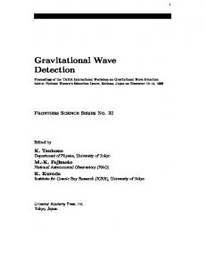
FIG. 1: Gravitational waveforms of three representative signals from the core collapse catalog of [33] with different values of the degree of differential rotation. The equation of state and the progenitor mass are fixed for all represented signals. Signal “s20a1o05 shen” (A) is show in the upper panel, signal “s20a2o09 shen” (B) is shown in the middle panel, and signal “s20a3o15 shen” (C) in the bottom panel. tb indicates the time of bounce.
At the final phase of their evolution, massive stars in the 940 M⊙ range develop iron-group element cores which are dynamically unstable against gravitational collapse. According to the standard model of type II/Ib/Ic supernovae, the collapse is initiated by electron captures and photo-disintegration of atomic nuclei when the iron core exceeds the effective Chandrasekhar mass. As the inner core reaches nuclear density and the equation of state (EoS) stiffens, the collapse stops and is followed by the bounce of the inner core. A strong shock wave appears in the boundary between the inner core and the supersonically infalling outer core. Numerical simulations try to elucidate if this shock wave is powerful enough to propagate from the outer core and across the external layers of the star. In the most accepted scenario, energy deposition by neutrinos, convective motions, and instabilities in the standing shock wave, together with general-relativistic effects, are necessary elements leading to successful explosions. In the core collapse scenario, conservation of angular momentum makes rotating cores with a period of one second to produce millisecond period proto-neutron stars, with a rotational energy of about 1052 erg. The bulk of gravitational radiation is emitted during bounce, when the quadrupole moment changes rapidly, which produces a burst of gravitational
waves with a duration of about 10 ms and a maximum (dimensionless) amplitude of about 10−21 at a distance of 10 kpc. Broadly speaking, GW signals from this mechanism exhibit a distinctive morphology characterized by a steep rise in amplitude to positive values before bounce followed by a negative peak at bounce and a series of damped oscillations associated with the vibrations of the newly formed proto-neutron star around its equilibrium solution. Catalogs of gravitational waveforms from core collapse supernovae have been obtained through numerical simulations with increasing realism in the input physics (see [32] and references therein). In our study, and for illustrative purposes, we employ only the catalog developed by Dimmelmeier et al. [33], who obtained 128 waveforms from general relativistic simulations of rotating stellar core collapse to a neutron star. The simulations were performed with the CoCoNuT code and include a microphysical treatment of the nuclear EoS, electron capture on heavy nuclei and free protons, and an approximate deleptonization scheme based on spherically symmetric calculations with Boltzmann neutrino transport. The simulations considered two tabulated EoS, those of [34] and [35] and a wide variety of rotation rates and profiles and progenitor
We turn next to describe the main features of the signals included in the two GW waveform catalogs we use to assess the two methods we have just presented.
6
Ω = Ωc,i
A2 , A2 + r2 sin2 θ
0.4 0.3 0.2 0.1
rh+/M
masses. The morphology and temporal evolution of the waveform signals of the catalog of [33] are determined by the various parameters of the simulations. The initial models include solar metallicity, non-rotating progenitors with masses at zero age main sequence of 11.2 M⊙ , 15.0 M⊙ , 20.0 M⊙ and 40.0 M⊙ . Rotation has a strong effect on the resulting waveforms and it is fixed by the precollapse central angular velocity which is set to values from Ωc,i = 0.45 to 13.31 rad s−1 . The angular velocity of the models is given by
0
−0.1 −0.2 −0.3 −0.4
(3.1)
r sin θ being the distance to the rotation axis, and A being a length parameterizing the degree of differential rotation. The specific values used in the simulations are A = 50, 000 km (almost uniform rotation), A = 1, 000 km, and A = 500 km (strong differential rotation). The GW amplitude maximum, |hmax |, is proportional to the ratio of rotational enTb ergy to gravitational energy at bounce, |W |b . The gravitational waveforms of the catalog are computed employing the Newtonian quadrupole formula where the maximum dimensionless gravitational wave strain is related to the wave amplitude AE2 20 by r 1 15 AE2 AE2 10 kpc 20 h= = 8.8524 × 10⁻²¹ 320 , (3.2) 8 π D 10 cm D where D is the distance to the source. We focus on three representative signals from the catalog to assess our algorithms. These three waveforms, shown in Fig. 1, cover the signal morphology of the catalog, as explained in [37]. These signals are labelled “s20a1o05 shen”, “s20a2o09 shen”, and “s20a3o15 shen” in the original catalog of [33]. We rename them, respectively, as signals “A”, “B”, and “C”, in the following, to simplify the notation. The three values of the degree of differential rotation produce, in particular, the most salient variations in the waveform morphology. B. Binary black holes catalog
The second type of GW signals we use for our study is that from the inspiral and merger of binary black holes. Along with the merger of binary neutron stars, such events are considered the most promising sources for the first direct detection of gravitational waves. This kind of systems evolve through three distinctive phases, inspiral, merger, and ringdown, each one of them giving rise to a different signal morphology. During the inspiral phase, the orbital separation between the two compact objects decays due to GW emission. Analytic approximations of general relativity such as postNewtonian expansions or the Effective One Body method describe to high accuracy the motion of the system and the radiated GW content during such inspiral phase. These were, until recently, the only approaches available to model the GW
0
2000
4000
6000
8000
10000
t/1000M FIG. 2: Gravitational waveform of a representative signal from the BBH catalog of [41], signal “0001”, used for our test purposes.
signal before the merger of the compact binary. After the merger, on the other hand, the resulting single BH asymptotically reaches a stationary state characterized by the ringdown of its quasi-normal modes of oscillation, whose waveform signal can be computed using standard techniques from BH perturbation theory. Either of these techniques, however, cannot be used to model the signal during the merger phase when the peak of the gravitational radiation is produced. At this phase, the signal waveform has to be computed solving the full Einstein equations with the techniques of numerical relativity, a long-lasting challenging problem that was only recently finally solved [38–40]. Since those breakthroughs many numerical relativity simulations of BBH mergers followed which led to the first BBH waveform catalogs of the entire signal (late inspiral, merger, and quasi-normal mode ringdown) based solely on fully numerical relativity approaches. Nowadays, numerical relativity waveforms for BBH mergers have become increasingly more accurate and span the entire seven-dimensional parameter space, namely initial spin magnitudes, angles between the initial spin vectors and the initial orbital angular momentum vector, angles between the line segment connecting the centers of the black holes and the initial spin vectors projected onto the initial orbital plane, mass ratio, number of orbits before merger (late inspiral), initial eccentricity, and final spin. State-of-the-art waveforms are in particular reported by Mrou´e et al [41], and these are the ones we use for our tests. This catalog includes 174 numerical simulations of which 167 cover more than 12 orbits and 91 represent precessing binaries. It also extends previous simulations to large mass ratios (from 1 to 8) and includes simulations with the first systematic sampling of eccentric BBH waveforms. In addition, the catalog incorporates new simulations with the highest BH spin studied to date (0.98). As for the case of the core collapse burst catalog, it is sufficient to focus on a representative signal from the BBH catalog in order to illustrate the performance of our denoising algorithms. To such purpose we select signal labelled “0001” from the Mrou´e et al [41] catalog, which is shown in Fig. 2.
7 0
REGULARIZATION PARAMETER ESTIMATION
Denoising results are strongly dependent on the value of the regularization parameter µ. The optimal value of µ that produces the best results cannot be set up a priori, and must be defined empirically. In the following, we perform an heuristic search for the optimal value of the regularization parameter to denoise a signal from the core collapse catalog of [33]. Since the procedure is the same regardless of the catalog, for the case of the BBH catalog we only give at the end of this section the results of the corresponding search. The goal is to find a small span of values of µ that provide a recovered (denoised) signal for all test signals under different signal-to-noise ratio (SNR) conditions. We shall apply the rROF algorithm for the time domain and the SB method for the frequency domain. Standard algorithms assume stationary additive white Gaussian noise. However, as the noise of actual interferometric detectors is non-white, since the sensitivity is frequency dependent, we have to adapt the denoising algorithms to take this fact into account. The weight distribution of the noise, w, according to the sensitivity curve of Advanced LIGO [45] is shown in Fig. 3. On the one hand, in the time domain we do not make any assumption about the noise, i.e., we use the rROF algorithm and we filter out the obtained result below the lower cut-off frequency of the sensitivity curve, according to the weight distribution. On the other hand, in the frequency domain we proceed as follows: Given the observed signal g, g = x + n,
10
weight coefficients
IV.
−1
10
−2
10
−3
10
1
2
10
3
10
10
Frecuency [Hz]
FIG. 3: Frecuency distribution of noise weight coefficients obtained from the Advanced LIGO sensitivity curve.
TABLE I: Values of the fidelity term and of the optimal value of µ for several time windows for the core collapse signals A, B, and C. The values are obtained after applying the SB algorithm in the frequency domain. ∆t (ms) 1000 500 250 125 62.5 31.25
||g − x||2L2 0.059 0.059 0.059 0.055 0.055 0.055
A 0.29 0.45 0.87 1.11 1.45 2.60
µopt B 0.28 0.49 0.98 0.98 1.66 3.05
C 0.22 0.36 1.06 0.61 2.80 3.94
(4.1)
where x is the signal from the catalog and n is the noise, we compute the Fourier transform of the mirror extension of g, gf . Then, we solve the following TV-denoising model Z µ vopt = argmin |∇v| + ||v − gf ||2w , (4.2) 2 v R where ||v||2w := w · |v|2 is the weighted (by w) L2 -norm of v in the frequency domain, by using the SB method for complex functions of real variable. Finally we compute the inverse Fourier transform of vopt , and after restricting its values to the appropiate time domain, we obtain the denoised signal uopt . We remark that due to its appropriate border treatment and computational efficiency, we use the matrix formulation of the SB method developed by Michelli et al (see [31] for details) when we address intensive real-time calculation. All signals of the core collapse catalog have been resampled to the LIGO/Virgo sampling rate of 16, 384 Hz and zero padded to be of equal length. For the SB algorithm in the frequency domain, signals have been Hanning windowed and mirror extended to avoid border effects in the Fourier Transform. We add non-white Gaussian noise to the signals generated as explained in Appendix A. To ensure the best conditions for the convergence of the algorithms and to avoid round-off errors, we also scale the amplitude of the test signals g of both catalogs to vary between -1 and 1. The values of µ we discuss in this section are hence determined by this normalization. As we use the same noise frame in all the experiments for comparison reasons, the amplitude of all signals is scaled to the
same values and differences are only given by the SNR which for a wave strain h is defined as v u Nf u X ˜ )|2 |h(f t 2 SNR = 4∆t ∆f , (4.3) S(fk ) k=1
˜ indicates the Fourier transform of signal h and S(fk ) where h is the power spectral density. The optimal value of the regularization parameter, µopt , is defined to be the one which gives the best results according to a suitable metric function applied to the denoised signal and the original one, measuring the quality of the recovered signal. In our case, we choose the peak signal-to-noise ratio, PSNR, based on the fidelity term, Eq. (2.2), � � N , (4.4) PSNR(dB) = 10 log10 MSE ||x − u||2L2 MSE = , (4.5) N where x is the original signal from the catalog, u is the processed signal after applying the algorithms, and N is the number of samples. First of all, we have to find the appropriate time window to perform this comparison. Since bursts have short duration (a few ms), if the time window is long the signal to compare with is going to be composed of mainly zeros, while, if it is short,
8 120
200
100
200
B
A
C
150
150
60
# counts
# counts
# counts
80 100
100
40 50
50
20 0
0
0.005
0.01
0.015
µrROF
0
0.02
100
A
0.05
µrROF
0.055
0
0.06
B
40 20
60 40 20
0
1
2
µSB
3
4
5
0
0.005
0.01
0.015
µrROF
0.02
C
80
# counts
60
0
100
80
# counts
# counts
0.045
100
80
0
0.04
60 40 20
0
1
2
µSB
3
4
5
0
0
1
2
µSB
3
4
5
FIG. 4: Histograms of the values of µopt for 500 noise generations for the three representative core collapse signals. The upper panels show the values of µopt for the rROF method in the time domain while the corresponding results for the SB method applied in the frequency domain are shown in the bottom panel. A SNR=15 is assumed.
some parts of the signal can be lost. To study this dependence, we seek for the value of µ in core collapse signals for which the fidelity term of the denoised signal matches the fidelity term of the original signal, that is, we seek for µopt subject to ||g − x||2L2 ≈ ||g − u||2L2 . Results of this study for the three representative signals from the core collapse catalog are shown in Table I. The SB method has been explicitly developed for discrete signals and it is well known that there exists a correlation between the number of samples and the value of µopt . Therefore, different (time or frequency) scales of the same signal cannot be recovered using the same value of µ. Indeed, we find that the values of µopt we obtain show certain dependence on the number of samples, which is roughly equal to √12 . Both, differences in ||g−x||2L2 and deviations from the previous ratio are due to the weight that the significant features of the GW signals have relative to the number of zeros. The rROF algorithm, on the other hand, reduces the staircase effect associated to the shrinkage operator in SB. The results of Table I for the SB method allow us to adjust the time window of the rROF method. From this comparison we choose a time window of 62.5 ms for the core collapse signals as it yields a complete representation of the waveforms without losing any significant feature. Once we have selected the time window, we must find the appropriate value of µ based on the PSNR value. First we seek the optimal value of the regularization parameter for several realizations of noise. The corresponding histograms with the optimal value of µ for both algorithms, SB and rROF, are shown in Fig. 4 for the three representative burst signals, assuming a SNR value of 15. We note that both distributions have the expected Gaussian shape. The variance of each distribution gives us a window of variability around the mean
value of µ to estimate the optimal one. The half-Gaussian in signal C for rROF is apparent and the whole Gaussian can be seen by log-scaling the range of µ. Having found the mean value of µ for a given signal through noise variations, we extend the analysis to consider different signal-to-noise ratios. We re-scale the amplitude of the three signals to fix the value of the SNR. The results are displayed in Fig. 5 for both algorithms. This figure shows that for all SNR values considered, the PSNR values peak around the optimal value of the regularization parameter. The span of values of µ to ensure a proper denoising is 1.5 − 3 for the SB method and 0.001 − 0.015 for the rROF algorithm. For very noisy signals (low SNR) the recovered ones are very oscillatory and cannot be distinguished from noise. In this case, it might be possible to apply other data analysis techniques to improve the results. From our analysis we observe that in some cases there is an interval of optimal values of µ giving the same regularized result, probably due to the lack of resolution in the data. Finally, we analyze the optimal value for all signals of the core collapse catalog assuming SNR=15. As shown in Fig. 6, the optimal value of µ is quite different across the entire catalog, particularly for the rROF algorithm (left panel). The values of µSB span the interval 1.5 − 2 and show a Gaussian profile, while for the case of the rROF algorithm they span the interval 0.001 − 0.05 and do not show an obvious trend. We note that although the range of values of µopt is large, it is still possible to perform the denoising procedure with acceptable results, by choosing the mean value for all the catalog signals and then tuning it up to find the value of µ that provides the best results. As mentioned at the beginning of this section we have also
9
55
SNR 5
−1
10
45
A
40
SNR 15
55 50 −3 10
50
55
PSNR (dB)
SNR 10 −2
10 µrROF
SNR 20
60
SNR 10 −2
10 µrROF
PSNR (dB)
SNR 15
50 45 −3 10
PSNR (dB)
50
60
SNR 20
55
PSNR (dB)
PSNR (dB)
PSNR (dB)
55
SNR 5
−1
10
50
SNR 15
50 45 −3 10
SNR 10 −2
10 µrROF
SNR 5
−1
10
45
B
45
SNR 20
55
C 40
0
1
2
3
µrROF
0
1
2
µrROF
3
58
SNR 20
4
0
1
2
µrROF
3
54
SNR 20
4
SNR 20
SNR 15
56
SNR 15
52
SNR 15
50
SNR 10
54
SNR 10
50
SNR 10
48
SNR 5
52
SNR 5
48
SNR 5
46 44
A
42
38
50 48
B
46
40
PSNR (dB)
52
PSNR (dB)
PSNR (dB)
54
40
4
5
10
15
µSB
42
20
44
C
42
44 0
46
40 0
5
10
µSB
15
20
38
0
5
10
µSB
15
20
FIG. 5: Dependence of the PSNR for different signal-to-noise ratios for the three representative core collapse signals. The upper panels show the values of PSNR for the rROF method in the time domain while the corresponding results for the SB method applied in the frequency domain are shown in the bottom panel. The insets in the top panels magnify the areas where the variations in the curves are larger.
30
35
25
30 25 # count
# count
20 15 10
20 15 10
5 0
Nevertheless, as we will show next, it is indeed possible to obtain acceptable results for all signals using a generic value of µ within the intervals discussed here which can then be fine-tuned to improve the final outcome.
5 0
0.01
0.02
0.03
µrROF
0.04
0.05
0
1.6
1.7
µSB
1.8
V. RESULTS
1.9
A. FIG. 6: Histograms of µopt for all signals of the core collapse catalog with SNR = 15. The left panel shows the span of values of µopt for the rROF method while the right panel displays the corresponding values for the SB method.
performed the same analysis with the entire catalog of BBH signals [41]. In this case we choose a window that contains the last 12 − 14 cycles before the merger (∆t ∼ 62.5 ms) for illustrative reasons. The results obtained are similar to those reported for the core collapse catalog, the optimal interval for the rROF algorithm being 0.001 − 0.01 and 1 − 3 for the case of the SB algorithm. We can conclude that the appropriate values of µ for both algorithms are restricted to a small enough interval which remains approximately constant for all signals of the catalogs and for different SNR. We stress that the concrete values of µopt reported here are mainly used as a rough guide to apply the denoising procedures. If the properties of the signals change, such as the sampling frequency, the number of samples, or the noise distribution, the values of µopt can also change, and it would become necessary to recompute them.
Signal Denoising
We start applying both TV denoising methods to signals from both catalogs in a high SNR scenario, namely SNR=20. Our aim is to show how the two algorithms perform the denoising irrespective of the nature of the gravitational waveform considered. We assume that there is a signal in the dataset obtained from a list of candidate triggers, and that all glitches have been removed. This simple situation allows us to test our techniques as a denoising tool to extract the actual signal waveform from a noisy background. We apply the proposed methods, rROF in the time domain and SB in the frequency domain, independently. The results from applying our denoising procedure to a signal from the core collapse catalog is shown in the three panels of Fig. 7. For the sake of illustration we focus on signal C, since the results are similar for the other two types of signals. The most salient features of this signal are the two large positive and negative peaks around t ∼ 0.06 s associated with the hydrodynamical bounce that follows the collapse of the iron core, and the subsequent series of small amplitude oscillations associated with the pulsations of the nascent proto-neutron star. Note that contrary to Fig. 1 the time in this figure is not
10
Amplitude
Amplitude
0.1
0.5 0
0.05
SNR 20
0
−0.05
−0.5
−0.1
−0.15
Time [s]
0.08
SNR 10 Amplitude
0.05 0 −0.05
0.04 0
−0.04
−0.1 −0.15
−0.08
0.1
0.04
Amplitude
Amplitude
Amplitude
0.1
0.05 0 −0.05
SNR 5
0.02 0
−0.02
−0.1
−0.04
−0.15 0
0.02
0.04
0.06 0.08 Time [s]
0.1
0.12
FIG. 7: Denoising of the core collapse waveform signal C with SNR = 20. Top panel: original signal (red dashed line) and nonwhite Gaussian noise (black solid line). Middle panel: Original and denoised (black solid line) signals for the SB method in the frequency domain with µ = 2.0. Bottom panel: Original and denoised signals for the rROF method in the time domain with µ = 0.09.
given with respect to the time of bounce. In the top panel we plot the original signal (red dashed line) embedded in additive non-white Gaussian noise (black solid line). The middle panel shows the result of the denoising procedure after applying the SB method in the frequency domain with µ = 2.0, and the bottom panel shows the corresponding result after applying the rROF algorithm in the time domain with µ = 0.09. The two large peaks are properly captured and denoised, most notably the main negative peak. This is expected due to the large amplitude of these two peaks, as TV denoising methods work best for signals with a large gradient. In turn, those parts of the signal with small gradients cannot be recovered as nicely, as seen in the damped pulsations that follow the burst and which have amplitudes much smaller than the noise. We note that both algorithms attenuate positive and negatives peaks due to noise effects. If desired, it would be possible to recover the actual amplitude of the main two peaks of the signal accurately by using a larger value of µ. However, this would introduce a more oscillating signal in the part of the waveform with small gradients. Such oscillations are consistently more common for the SB method than for the rROF method, as can be seen from the middle and bottom panels of Fig. 7. The effect of varying the SNR on the denoising procedure
0.04
0.05
0.06
0.07
0.08
Time [s] FIG. 8: Denoising of the core collapse waveform signal C for the rROF method with µ = 0.09 for three values of the SNR, 20 (top), 10 (middle), and 5 (bottom).
is shown in Fig. 8 for the same core collapse waveform C. This figure magnifies the signal around the late collapse and early post-bounce phase, i.e. 0.04s < t < 0.08s. The three panels show, from top to bottom, the comparison between the denoised and the original signal for SNR=20, 10, and 5, respectively. Only the results for the rROF algorithm with µ = 0.09 are shown, as the results and the trend found for the SB method are similar (only more oscillatory in the small gradient part of the signal for the latter). This figure shows that, as the SNR decreases, the denoised signal recovers the original signal worse, as expected. While the amplitude of the oscillations of the denoised signal increases in the part with small gradients, it is nevertheless noticeable the correctness of the method to recover the amplitude of the largest negative peak of the signal even for SNR=5. We stress that all three signals have been denoised applying the same value of µ and recall that the study of the dependence of µ on the SNR (Section IV) predicts a lower value of µopt as the SNR decreases to obtain the best results. Therefore, the effect of using a value of µ greater than the optimal one is also noticeable in the middle and lower panels of Fig. 8. The amount and amplitude of the oscillations of the denoised signals in small gradient regions can be somehow made less severe when both algorithms are applied sequentially. This is shown in Fig. 9 for the GW burst signal C with SNR=20. The denoised signal in black in this figure is the
11 0.1
Amplitude
0.8
Amplitude
0.05 0
−0.05
0 −0.4 −0.8 Time [s]
−0.1
0.1 0.05
0.06
0.07
0.08
Time [s] FIG. 9: Denoising of the core collapse waveform signal C with SNR = 20 after applying both algorithms sequentially, rROF first with µ = 0.05 followed by SB with µ = 8.
Amplitude
0.04
0.4
0.05 0
−0.05 −0.1 Time [s]
result of applying an initial denoising with the rROF algorithm in a 1 s window followed by a second step with the SB method in the frequency domain using a 125 ms time window. The values of the regularization parameters employed in this case are µ = 0.05 for the rROF algorithm and µ = 8 for the case of the SB method. We note that, in general, larger values of the regularization parameters are required when applying both methods sequentially because regularization is accumulative. Indeed, the output of the first step contains less noise and, therefore, the second step needs larger values of µ, i.e. less regularization. We turn next to apply the denoising procedure to the BBH catalog. For illustrative purposes we focus on a single signal of such catalog, signal “0001”, as this suffices to reveal the general trends. The results are shown in Fig. 10. As before, the top panel shows the original signal (red dashed line) embedded in additive non-white Gaussian noise (black solid line). The middle panel shows the result of the denoising procedure after applying the SB method in the frequency domain with µ = 1.6, and the bottom panel shows the corresponding result after applying the rROF algorithm in the time domain with µ = 0.0026. A value of SNR=20 is assumed. To better visualize the results we display only the last few cycles up until the two black holes merge. As BBH waveforms have longer durations than bursts and the characteristics of the signal change over time, scales between the beginning and the end of the signal are significantly different. This becomes clear in Fig. 10 where as a result of the scale variations in frequency and amplitude during the late inspiral and merge, the signal cannot be properly denoised throughout using the same value of µ. Typically we find that using a comparatively large value of µ helps to accurately recover larger amplitudes and high frequencies than lower frequencies and amplitudes, and vice versa. The reason for this is again due to the fact that the methods we employ are gradient dependent, preserving the large gradients and removing the small ones. On the one hand, choosing a low value of µ to recover low frequency cycles makes the merger signal to be treated as high frequency noise. On the other hand, choosing a high value of µ to recover the merger part produces high
Amplitude
0.1 0.05 0
−0.05 −0.1 0
0.01
0.02
0.03
0.04
0.05
0.06
Time [s] FIG. 10: Denoising of the BBH waveform signal “0001” with SNR = 20. Top panel: original signal (red dashed line) and nonwhite Gaussian noise (black solid line). Middle panel: Original and denoised (black solid line) signals for the SB method in the frequency domain with µ = 1.6. Bottom panel: Original and denoised signals for the rROF method in the time domain with µ = 0.0026.
oscillations in the rest of the signal. We have checked that it is nevertheless possible to obtain good results for the entire BBH waveform train using different values of µ for different intervals of the waveform.
B. Signal Detection
From the previous analysis, it becomes manifest that in a low SNR situation our denoising algorithms alone cannot remove enough noise to produce detectable signals. In order to improve our results in such a situation, we can combine our techniques with the use of spectrograms. Such an approach is usually employed in GW data analysis to seek for transient power peaks in the data that could correspond to actual gravitational wave signals, assuming that all known transients have been removed from the data [4, 5, 11]. First, we have to check if the information we can obtain from the spectrogram would be modified by the application of our techniques. To do this we compare the spectrogram from an original noisy signal with SNR=10 with the spectrogram of the corresponding denoised signal. The results are shown in Fig. 11 for the core collapse signal C. The spectrogram of
12
FIG. 12: Spectrogram of the core collapse signal C for SNR=5. The excess power around 0.5 s is supposed to be produced by the gravitational wave signal.
channel, using first the SB method as a filter and then applying the rROF algorithm in order to obtain the signal waveform. Fig. 12 shows that the power peak of the signal (red color) is clearly distinguishable from the noisy background (green-blue colors). This findings give us confidence to use our algorithms as a denoising tool jointly with other data analysis techniques. FIG. 11: Spectrograms of the original noisy signal (top panel) and denoised signal (bottom panel) for the core collapse signal C and SNR =10. The higher values of the spectral power density are shown in red, while the lower power is represented in blue.
the original signal is shown in the top panel and the denoised spectrogram is shown in the bottom panel. Red color represents high spectral power while lower power is represented in blue. In order to produce Fig. 11 we first apply the rROF algorithm in the time domain followed by the SB method in the frequency domain, both for a 1s time window, and then we calculate the spectrogram. The power peak around 0.5s corresponds to the GW signal which is clearly distinguishable in both spectrograms, and its structure remains similar after the denoising procedure. An example of the application of the spectrogram together with our algorithms in a low SNR situation where the spectrogram alone would not reveal any high power peak, is shown in Fig. 12. This figure displays the denoised spectrogram of the same core collapse signal C originally embedded in nonwhite Gaussian noise but now with SNR=5. In this case we have a dataset which contains 1s of data from the detector. The exact arrival time of the signal is unknown and is what we want to determine by computing the spectrogram. In order to find the time of arrival of the signal we integrate the power of the first 2000 Hz for each temporal channel and look for the channel that contains the maximum power. After selecting this channel we perform the denoising procedure only in this
VI.
SUMMARY AND OUTLOOK
In this paper we have presented new methods and algorithms for denoising gravitational wave signals. The methods we use are based on L1 norm minimization and have been originally developed and fully tested in the context of image processing where they have been shown to be the best approach to solve the so-called Rudin-Osher-Fatemi denoising model. We have applied these algorithms to two different types of numerically-simulated gravitational wave signals, namely bursts produced from the core collapse of rotating stars and chirp waveforms from binary black hole mergers. The algorithms have been applied in both the time and the frequency domain. Both of our methods, SB and rROF, reduce the variation of the signal, assuming that due to its randomness the larger variations are due to the noise. We have performed an heuristic search to find the set of values best suited for denoising gravitational wave signals and have applied the methods to detect signals in a low signal-to-noise ratio scenario without any a priori information on the waveform. In particular, the rROF algorithm in the time domain has led to satisfactory results without any assumption about the noise distribution. On the other hand, in order to apply the SB method in the frequency domain, we have selected a particular weight distribution. This distribution can be chosen freely so as to adjust it to the specific spectral characteristics of the noise or of the detector sensitivity curve. Overall, we conclude that the techniques we have presented in this paper may
13 be used along with other common techniques in gravitational wave data analysis (e.g. spectrograms) to help increase the chances of detection. Likewise, these methods should also be useful to improve the results of other data analysis approaches such as Bayesian inference or matched filtering when used as a noise removal initial step that might induce more accurate results for the aforementioned traditional methods. In future work we plan to further test these TV-based methods in a more realistic setup by using real noise from the detectors instead of the somewhat simplistic non-white Gaussian noise employed in this paper. The presence of transient glitches may be a crucial factor spoiling the results as our methods cannot discriminate if the denoised signals correspond to a real signal or a glitch or outlier. There is room to improve the capabilities of the methods by incorporating information about the sources into the algorithms through the use of signal dictionaries from numerical relativity waveform catalogs and known glitches, and through the implementation of a machine learning algorithm to both, improve the pure denoising results and remove spurious information. Acknowledgments. It is a pleasure to thank I.S. Heng and A. Sintes for helpful discussions. This work was supported by the Spanish MICINN (AYA 2010-21097-C03-01), MINECO (MTM2011-28043) and by the Generalitat Valenciana (PROMETEO-2009-103).
Appendix A: Noise Generation
We generate non-white Gaussian noise whose shape corresponds to Advanced LIGO in the proposed broadband configuration. For this purpose, we employ the algorithm libraries (LAL) [46] provided by the LIGO Scientific Collaboration (LSC) that p include one-sided detector noise power spectral density S(f ). If necessary, random noise series can be obtained weighting samples from Normal distribution by noise
[1] G. M. Harry (for the LIGO Scientific Collaboration), Class. Quantum Grav., 27, 084006 (2010). [2] “Advanced Virgo Baseline Design”, The Virgo Collaboration, VIR-0027A-09 (2009); available from https://pub3.egogw.it/itf/tds/ [3] Y. Aso, Y. Michimura1, K. Somiya2, M. Ando, O. Miyakawa, T. Sekiguchi, D. Tatsumi, H. Yamamoto, and the KAGRA Collaboration, Phys. Rev. D 88, 043007 (2013) [4] P. Ajith, T. Isogai, N. Christensen,R. Adhikari, A.B. Pearlman, A. Wein, A.J. Weinstein and B. Yuan. Phys. Rev. D 89,122001 (2014) [5] A. Di Credico (for the LIGO Scientific Collaborations), Class. Quantum Grav. 22, S1051-S1058 (2005). [6] P. Jaranowski and A. Kr´olak, Living Rev. Relativity 15, 4 (2012). [7] B.P. Abbott et al. Rep. Prog. Phys. 72, 076901(2009). [8] J. Abadie et al. (The LIGO Scientific Collaboration, The Virgo Collaboration) Phys. Rev. D 85, 022001 (2012). [9] P. Prix, and B. Krishnan, Class. Quantum Grav. 26, 204013, (2009). [10] http://einstein.phys.uwm.edu/
power spectral density, p S(f ) N(µ, σf2 ) , Re(˜ n(f )) = 2 p S(f Im(˜ n(f )) = N(µ, σf2 ) , 2 {˜ n(f ) ∈ C : f = 0, ∆f , 2∆f , ..., (N − 1)∆f },
(A1) (A2)
(A3)
where ∆f = FNs being Fs the sampling rate and N the number of samples. Mean (µ) and variance (σf2 ) are set to 0 and 1 respectively as corresponds to the standard normal distribution. As noise time-series are real-valued, in the frequency domain noise must satisfy n ˜ (−f ) = n ˜ ∗ (f ) ,
(A4)
and Im{˜ n(0)} = Im{˜ n(fN y )} = Im{˜ n(−fN y )} = 0 , (A5) where fN y = F2s corresponds to the Nyquist frequency. Properties of the Fourier transform assure that the Gaussian character of the noise signal is preserved when changing domain. Therefore, we obtain noise time-series applying the discrete Fourier Transform (DFT) n ˜ (fk ) =
N −1 X
n(tj )e
−2πi N kj
,
(A6)
j=0
n(tj ) =
N −1 2πi 1 X N (fk )e N kj . N
(A7)
k=0
[11] W. G. Anderson and R. Balasubramanian. Phys. Rev. D 60, 102001 (1999). [12] S. Bose, A. Pai, and S. V. Dhurandhar, Int. J. Mod. Phys. D 9, 325 (2000). [13] S. Klimenko, SI Yakushin, A. Mercer and G. Miselmakher. Class. Quantum Grav. 25, 114029 (2008). [14] C. R¨over, M.A. Bizouard, N. Christensen, H. Dimmelmeier, I.S. Heng, and R. Meyer, Phys. Rev. D 80, 102004 (2009). [15] W. J. Engels, R. Frey and C. D. Ott. arXiv:1406.1164 (2014). [16] L.I. Rudin, S. Osher and E. Fatemi, Physica D, 60 259-268 (1992) . [17] D. L. Donoho, IEEE Transactions on Information Theory, 52(4), 1289-1306 (2006). [18] T. Goldstein and S. Osher, J. Imag. Sci. 2, 323 (2009). [19] M. Irani and S. Peleg, J. Vis. Commun. Image Represent. 4, 324-335 (1993). [20] A. Marquina, SIAM J. Imaging Sciences, 2,1, 64-83 (2009). [21] I. Cordero-Carri´on, P. Cerd´a-Dur´an, H. Dimmelmeier, J.L. Jaramillo, J. Novak, and E. Gourgoulhon, Phys. Rev. D 79, 024017 (2009). [22] A. Marquina and S. Osher, SIAM J. Sci. Comput., 22, 387-405
14 (2000). [23] C.R. Voguel and M.E. Oman, IEEE Trans. Image Process., 7, 813-824 (1998). [24] S. Osher, M. Burguer, D. Goldfarb, J. Xu, and W. Yin, Physica. D 60, 259-268 (2005). [25] D. L. Donoho, IEEE Trans. Inform. Theory, 41, 613-627 (1995). [26] D. L. Donoho and I. M. Johnstone, Biometrika, 81, 425-455 (1994). [27] E. J. Cand`es, J. Romberg and T. Tao, IEEE Trans. Inform. Theory, 52, 2 (2006). [28] R. Tibshirani, J. Royal Statistical Society. Series B, 58, 267-288 (1996). [29] Y. Meyer, “Oscillating Patterns in Image Processing and Nonlinear Evolution Equations”, AMS, Providence, RI, (2001). [30] L. Bregman ,USSR Computational Mathematics and Mathematical Physics, 7, 200-217 (1967). [31] C. A. Micchelli, L. Shen, and Y. Xu, Inverse Problems, 27, 045009 (2011). [32] C. L. Fryer and C. B. New, Living Rev. Relativity 14, (2011). [33] H. Dimmelmeier, C. D. Ott, A. Marek, and H.-T. Janka, Phys. Rev. D 78, 064056 (2008). [34] H. Shen, H. Toki, K. Oyamatsu, and K. Sumiyoshi, Prog. Theor.
Phys. 100, 1013 (1998). [35] J. M. Lattimer, and F. D. Swesty, Nucl. Phys. A 535, 331 (1991). [36] URL http://www.mpa-garching.mpg.de/rel_hydro/wave MPA Garching Gravitational Wave Signal Catalog. [37] J. Logue, C. D. Ott, I. S. Heng, P. Kalmus, and J. H. C. Scargill. Phys. Rev. D 86, 044023, (2012). [38] F. Pretorius, Phys. Rev. Lett. 95, 121101 (2005). [39] M. Campanelli, C. O. Lousto, P. Marronetti, and Y. Zlochower. Phys. Rev. Lett. 96, 111101 (2006). [40] J. G. Baker, J. Centrella, D. Choi, M. Koppitz, and J. van Meter Phys. Rev. Lett.96, 111102 (2006). [41] A.H Mrou´e et al, Phys. Rev. Lett. 111, 241104 (2013). [42] The MathWorks Inc. Natick, MA 01760, USA. http://mathworks.com/products/matlab/. [43] C. S. Burrus and T. W. Parks. DFT/FFT and Convolution Algorithms. Wiley, (1984). [44] L. Blanchet, Living Rev. Relativity, 17, 2 (2014). [45] B.S. Sathyaprakash and B.F. Schutz, Living Rev. Relativity, 12, 2 (2009). [46] J. Creighton et al. LAL software documentation (2007), URL http://www.lsc-group.phys.uwm.edu/daswg/projects