Proceedings of DETC99/CIE 1999 ASME Design Engineering Technical Conference September 12-15, 1999, Las Vegas, Nevada
DETC99/CIE-9085 TOWARDS A DECISION-BASED DISTRIBUTED PRODUCT REALIZATION ENVIRONMENT FOR ENGINEERING SYSTEMS
1
1
1
2
3
Jonathan F. Gerhard , Scott J. Duncan , Yong Chen , Janet K. Allen , David Rosen , Farrokh 4* 5 Mistree , Andrew D. Dugenske The George W. Woodruff School of Mechanical Engineering Georgia Institute of Technology Atlanta, GA 30332-0405 USA
ABSTRACT We imagine a future in which geographically distributed engineers collaboratively develop, build, and test solutions to design-manufacture problems encountered in the product realization process. In this context, we want to provide a foundation to support the realization of industrial products for a global marketplace through distributed design and manufacture. Specifically, we want to provide a platformindependent framework to integrate distributed and heterogeneous software resources to support the computationally intensive activities in the product realization process, anchored in the philosophy of decision-based design. In this paper, we present a prototype platform-independent framework based on an experimental version, called P2, of the Sandia Product Realization Environment (PRE). We describe the implementation of this framework to design and prototype gear transmissions using commonly available software assets. Keywords: Distributed design and manufacture, product realization environment, rapid prototyping, rapid tooling, robust concept exploration method NOMENCLATURE API Application Programming Interface DBD Decision-Based Design DO Distributed Object DSPT The Decision Support Problem Technique
PRE The Sandia Product Realization Environment P2 An experimental version of the Sandia Product Realization Environment RCEM Robust Concept Exploration Method RP Rapid Prototyping RTTB Rapid Tooling TestBed (in the Rapid Prototyping and Manufacturing Institute at Georgia Institute of Technology) XML Extensible Markup Language 1. FRAME OF REFERENCE: DISTRIBUTED DESIGN AND MANUFACTURE The software world today is one of great richness and diversity. Heterogeneous hardware and software systems abound, providing a wide variety of information and services in a wide variety of domains. While most of these tools are valuable sources of information when used in isolation, there is increasing demand for software that can inter-operate to exchange information and services to solve complex multidisciplinary problems (Genesereth, 1997). It is now critical for a manufacturing enterprise that design and manufacturing are not isolated from each other, as well as from other business activities. Information must flow easily and bidirectionally. Commercial, in house, and legacy software must be easily integrated into the enterprise information flow (Pancerella and Whiteside, 1998). Currently, commercial and legacy software
1
Graduate Research Assistant, Systems Realization Laboratory Senior Research Scientist, Systems Realization Laboratory 3 Associate Professor, Systems Realization Laboratory 4 Professor, Systems Realization Laboratory * Corresponding Author. Email:
[email protected]. Phone/fax: (404)894-8412/9342 5 Research Manager, Manufacturing Research Center, Georgia Tech 2
1
Copyright © 1999 by ASME
tools have problematic interfaces because of the heterogeneous information formats used in both the control and operation of different software. With the growing number of information sources available, this problem of how to integrate distributed, heterogeneous information sources becomes more and more critical (Knoblock and Ambite, 1997). At the same time, increased competition is forcing product realization to change: to become faster and to leverage facilities and expertise, wherever they may be (Rosen, 1998). 1.1 A Vision of the Future Product Realization Today's manufacturing environment is an emerging global enterprise (Karne, et al., 1998). We imagine a future in which geographically distributed engineers collaboratively develop, build, and test solutions to design-manufacture problems encountered in the product realization process. We believe that these designers will operate in a distributed system; a distributed system being defined as physically or ideologically separated entities, belonging to the same system, which communicate cooperatively (Akyildiz, et al., 1989, Champine, et al., 1980). Physical and geographical separation are synonymous; ideological separation is the separation of microlevel goals of the cooperating entities, such as a designer and a manufacturer (D'Ambrosio, et al., 1998). The lack of communication between different designers who operate at different points in a product realization process is perhaps the classic design and manufacture problem.
Accordingly, we want to provide a platform-independent framework to integrate distributed and heterogeneous software resources to support the computationally intensive activities in the product realization process, anchored in the philosophy of decision-based design. Specifically, we analyze an example usage scenario, still under development, in which we design and prototype (using rapid prototyping technology), a gear transmission from a cordless drill. In addressing our research question, we intend to provide maximal value to a designer by (1) anchoring our work in design theory and (2) emphasizing the use of available assets. We propose to expand the information gathering activity performed by design solution software to include distributed and heterogeneous software resources in order to realize more hi-fidelity analysis and simulations to support response surface methodology and robust design practices. We also intend to demonstrate the integration of design visualization tools and rapid prototyping tools to provide means to communicate and test designs. Finally, because many valuable commercial, in house, and legacy software resources are well established, we believe that it is more important to provide for the integration of reusable heterogeneous software assets over time than to develop standard file formats or specific point solutions that are only valuable for a limited amount of time.
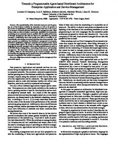
2. A DISTRIBUTED PRODUCT REALIZATION ENVIRONMENT USAGE SCENARIO This research is being conducted with the hardware and software resources in the Systems Realization Laboratory at 1.2 Research Question and Objectives Georgia Tech (http://www.srl.gatech.edu). We have integrated Although advancements will need to be made in many SRL technologies and research efforts into this research, areas to realize a truly integrated global enterprise, we have including the Decision Support Problem, the Robust Concept focused our research on one point: Exploration Method, and the Rapid Tooling TestBed. In this section we first provide an overview of our product realization • How do we design an open architecture, consisting of example which we are using to investigate the research reusable available assets, to realize the platformquestion. We then discuss the mathematical formulation of the independent integration of distributed and heterogeneous gear transmission design problem as a compromise Decision information resources for the product realization process? Support Problem. We 1. Designer Input: discuss the Robust Concept Power, RPM, gear ratio Exploration Method (RCEM) 2. Solve Compromise DSP which we use as a model of a With Simple Models designer's information gathering activities. Finally, = (W · P)/(F · Y) σ bending t Simple we present the Rapid Tooling Model 3. Build Response Surface TestBed (RTTB), with which Reduced From FEA we rapid prototype the gear Design Space 4. Solve Compromise designs. DSP With Response Surface
Accurate Model
5. Visualize Final Model
Response Surface
6. Rapid Prototype Final Model
Point Answer
Figure 1 - Gear Transmission Usage Scenario
VRML Prototype
2.1 Elements of Our Product Realization Example To explore distributed design and manufacture, we developed an example design and manufacturing usage
Plastic Prototype
2
Copyright © 1999 by ASME
scenario: we design and prototype (using rapid prototyping technology) the spur gears in a single layer of a cordless power drill transmission, which is analyzed in (Conner, et al., 1999). We chose a simple design problem that is well understood to allow us to focus on supporting the solution of the problem in a distributed computing environment. The problem is relevant to commonly available engineering software analysis tools. The solution to the design and manufacturing problem forms a process: we provide a diagram of the main steps and their results in this process in Figure 1. 1. 2. 3.
4.
5. 6.
First, we get the design parameters from a designer. We formulate and solve a compromise DSP in design solution software with simple mathematical models of gear behavior to reduce the design space. We then build a response surface in the reduced design space by parametrically generating CAD models of different parameter sets and simulating their performance with FEA. These analysis resources are distributed across platforms. We then solve a second compromise DSP, again in the design solution software, using the response surface built from the FEA results. This yields a point solution that must be accepted by the designer. The designer is presented a VRML model of the transmission layer along with FEA results developed from analyzing the final model. Upon acceptance of the final solution by the designer, we give the solid model to the Rapid Tooling TestBed (RTTB) system for rapid prototyping; the RTTB is also distributed from the design solution software.
We now describe some of the elements of the usage scenario in detail, including the design problem, the solution method, and the Rapid Tooling TestBed system. 2.2 The Compromise DSP for Gear Transmission Design We believe that design is a human-centered, intellectual, cognitive, decision-based activity, which is characterized by the conversion, "of information that characterizes the needs and requirements of a product into knowledge about a product" (Bras and Mistree, 1991). Foundational to our thinking is Decision-Based Design, a design paradigm in which one recognizes that principal role of a designer is to make decisions (Shupe, 1988) (Mistree, et al., 1990). We posit that at the heart of the decision-making process, there is a need for a humancomputer partnership (Mistree, et al., 1990). One embodiment of DBD is the Decision Support Problem (DSP) Technique, which is an open system of methods and tools for decision support in engineering design (Muster, et al., 1988). The compromise DSP is a multi-objective mathematical construct which is a hybrid formulation based on mathematical programming and goal programming (Mistree, et al., 1990). DSPs can be solved using various types of design solution
1. Outer Frame Ring
2. Sun 3. Planets
Figure 2 - Planetary Spur Gears software, including DSIDES (Mistree, et al., 1993), Crystal Ball, LINGO and OptdesX, to name a few. The compromise DSP is used to determine the values of the design variables which satisfy a set of constraints and achieve as closely as possible a set of conflicting goals (design objectives) as is often the case in robust design and complex systems design. An extensive discussion can be found in (Mistree, et al., 1993). We have adopted a mathematical model, focusing on contact and bending stresses, for a transmission layer of spur gears in a cordless drill, depicted in Figure 2. For a complete discussion, refer to (Conner, et al., 1999). Given an input power and rpm, the goal for this gear design problem is to determine the dimensional parameters of the gears such as to minimize the number of planetary gears and material used while meeting a target gear ratio and satisfying the physical constraint of the maximum allowable stress for the material. In addition to the goals of (1) minimizing the number of planetary gears and (2) minimizing material used, we add the goal of minimizing the variance in mass in order to search for solutions that make the amount of material used the least sensitive to changes or perturbation of the system variables (Chen, et al. 1996a). The equations defining the physical relationships in gear design are presented in (Conner, et al., 1999). A compromise DSP for the spur gear transmission design is shown in Table 1. As discussed previously, we implement this design problem in several stages that improve the fidelity of the design analysis, including the analytical equations in (Conner, et al., 1999) and simulation FEA models. This method has been developed from the Robust Concept Exploration Method (RCEM), which is described next. 2.3 The Robust Concept Exploration Method The Robust Concept Exploration Method (RCEM) is an ideal model of a designer's activities in a distributed computing environment. The RCEM has been developed to facilitate quick evaluation of different design alternatives and generation of toplevel design specifications with quality considerations in the early stages of design (see, e.g., Chen, et al., 1996b).
3
Copyright © 1999 by ASME
Table 1 - Compromise DSP for a Single Layer of a Planetary Transmission (Conner, et al., 1999) Mathematical Formulation of C-DSP Given: ! Planetary/epicyclic transmission model analysis equations ! Output characteristics of a specific DC motor [Pmax, max] ! Standard gear sizes and diametral pitches ! Material selection: powdered metal gears [σb,allowable ≅ 75,000 psi, σc,all>180,000 psi, ρ ≅ 0.28 lbs/in3] Find: ! The system variables: Diametral pitch, Pd • Pitch diameter of outer frame ring, d1 • Number of teeth on sun, N2 • Number of planets, Np • Face-width, F • ! Deviation variables di+, di-, i = 1, 2, 3 • Satisfy: ! The system constraints: • σb≤σb,all • σc≤σc,all Lifetime: infinite (107 cycles) • • ωout/ωin = (ωout/ωin)pre-existing (See Table 4.?) d1 = (d1 of existing transmissions) • ! The bounds on the system variables: N1, N2, N3 ≥ 12 • N1, N2, N3 integers • • 3≤ Np ≤ 5 • • •
Pd must be a standard size di-, di+ > 0, i = 1, . . . number of product variants di- * di+ = 0, i = 1, . . . number of product variants
!
System goals:
1.
Number of components (goal of 6): N C + d − − d + = 1 1 1
2.
Mass (goal of 0.03 lbs.): m + d − − d + = 1 2 2 0.03
6
2 Mass Variance (Normalized): σ mass + d − − d + = 1 2 2 0.2 Minimize: ! The deviation function (Archimedean formulation):
3.
+
+
Z = W1d1 + W2 d 2 + W3d 3
+
The RCEM is an integration of several methods and tools—robust design methods (see, e.g., Phadke, 1989), the Response Surface Methodology (see, e.g., Myers and Montgomery, 1995), and Suh's Design Axioms (Suh, 1990)— within the compromise DSP (Mistree, et al., 1993). A review of the wide variety of applications that have successfully employed the RCEM is given in (Simpson, et al., 1997). The RCEM is a four-step process: Step 1 - Classify Design Parameters: Given the overall design requirements, (a) classify different design parameters as either control factors, noise factors, or responses following the terminology used in robust design, and (b) define the concept exploration space.
Step 2 - Screening Experiments: This step requires the use of a point generator, simulation programs, and an experiment analyzer to set up and perform initial screening experiments and analyze the results. The results of the screening experiments are used to (a) fit low-order response surface models, (b) identify significant main effects, and (c) reduce the design region. Step 3 - Elaborate the Response Surface Model: This step also requires the use of the point generator, simulation programs, and an experiment analyzer to set up and perform secondary experiments and analyze the results. The results from the secondary experiments are used to (a) fit second-order response surface models which replace the original computer analyses, (b) identify key design drivers and the significance of different design factors and their interactions, and (c) quickly evaluate different design alternatives and answer "what-if" questions in Step 4. Step 4 - Generate Top-Level Design Specifications with Quality Considerations: Once accurate response surface models have been created, Step 4 involves the use of the compromise DSP to determine top-level design specifications with quality considerations. The original analyses or simulation programs are replaced by response surfaces which are functions of both control and noise factors. Different quality considerations and multiple objectives are incorporated in the compromise DSP which is then solved to determine robust, toplevel design specifications. 2.4 Modifications to RCEM method For the initial incarnation of our distributed design process, we alter the first two steps of the RCEM because of the low level of complexity of our design space. Bending and contact stresses are not accurately modeled by mechanics equations, as they rely heavily on imprecise worst-case-scenario geometric derating factors. Rather than apply excessive safety factors in response, thus driving up material usage, we rely on distributed CAD and FEA resources to accurately verify stress levels for any given gear with specified parameters. However, we do not desire to use FEA to verify models across the entire design space, as this would be very computationally expensive. Since the mechanics models do provide a somewhat close approximation of gear performance, we rely on them to model stress constraints in a preliminary formulation of the compromise DSP, which replaces the first and second steps of the RCEM. This cDSP is solved for a point solution, around which a central composite design (CCD) of experiments can be conducted. The remaining Steps 3 and 4 of the RCEM are conducted as normal. 2.5 The Rapid Tooling TestBed (RTTB) To provide a manufacturing context in our product realization example, we are working with the Rapid Tooling TestBed (RTTB). The RTTB is an NSF funded rapid prototyping system that is under development in the Rapid Prototyping and Manufacturing Institute (RPMI) at Georgia Tech (http://rpmi.marc.gatech.edu), which is closely associated
4
Copyright © 1999 by ASME
with the Systems Realization Laboratory. The RTTB is an experimental testbed to "integrate design process and fabrication process models with product models to enable a designer to instantiate an approved design process with the appropriate tasks, personnel, vendors, software, and equipment" (Rosen, 1998). The RTTB is being developed to fabricate injection-molding tools and for the subsequent molding of parts using those tools. Stereolithography (SLA) is used to fabricate tools. Additional processes are being explored. Given a preliminary component design as input, the testbed software facilitates the selection of appropriate component material and fabrication process, the tailoring of the design to that material and process, the design of the molding tools for the components, the fabrication of these tools, and the design of the molding process to mold the component. The execution and on-line supervision of the RTTB activities on the distributed underlying software and hardware will be supported in the P2 environment (Rosen, 1998). A diagram of the events and phases in the proposed RTTB system is shown in Figure 3. Design
Design for Manufacture
Part Representation Preliminary Selection of Materials Design Specification
RTTB Events
Preliminary Selection of SFF Techniques
Preliminary Selection of IJM Techniques
Geometric Tailoring Selection of Mold Configuration
Combining SFF & IJM Techniques
Resource Selection
Current Usage Scenario Event Timeline
Figure 3 - RTTB System Structure A part representation and the design specifications are given to the RTTB system and stored in a database. For rapid tooling, the mold representation is created from the part representation and a preliminary selection is made of mold materials, mold production processes, and part production processes to narrow the field of possible Rapid Prototyping (RP) technologies and materials to fabricate the mold. It is also desirable to improve the mold design through modifying the part in the Geometric Tailoring event; the selection of the materials and processes are coupled with the determination of the most feasible mold and part dimensions (Rosen, et al., 1998). A discussion of the coupled Selection-Selection DSPs used in the RTTB, which take into account feasible material and process combinations and the material properties, accuracy, and build time, can be found in (Herrmann, et al., 1999). 2.6 Usage of RTTB Because at this time we are directly prototyping the gears instead of molds for rapid tooling, we only use the Resource Selection event in the DFM phase to demonstrate the
integration of a manufacturing model with the P2 environment. With continued development of the RTTB in the P2 environment, more RTTB events will be used in the usage scenario. Additionally, we only use Stereolithography Apparatus (SLA) machines and their related materials as our process and material selection alternatives at this time because stereolithography is both the most widely used RP technology (Jacobs, 1996) and because we have a good understanding of SLA from other projects in the RPMI. The method used to select a suitable SLA machine and related material from the available alternatives is the Coupled RP/VP Selection DSP, fully discussed in (Rosen, et al., 1998). 3. THE CONFIGURATION OF AVAILABLE (SOFTWARE) ASSETS IN THE P2 ENVIRONMENT In this section we discuss the implementation of a design and manufacturing environment for the usage scenario presented in Section 2. We first introduce the Sandia PRE and P2 systems. We then present the system architecture that has been implemented with P2. We then Manufacture describe the specific configuration of engineering analysis tools with the Sandia P2 environment to implement the architecture. 3.1 The Sandia Product Realization Environment (PRE) We have implemented the system Mold architecture with the P2 framework, Fabrication an experimental version of the PRE framework, developed by Sandia National Laboratories (http://daytona.ca.sandia.gov/pre/). The initial implementation is based on the Common Object Request Broker Architecture (CORBA), and is an industrial-strength system with many complexities due to the underlying CORBA framework. The new system, currently known as P2, is an experimental testbed under development using Java and XML technology: Java and XML make it possible to design a smaller, easier to use, and more universal version of PRE that is equally robust (in its final implementation). PRE provides a platform and operating system independent communications framework for enterprise integration and product realization. The PRE framework defines common data and application interfaces to enable rapid and easy integration of distributed tools, including commercial, in-house, legacy, and newly developed tools, which in turn makes stand-alone software tools reusable components. The framework provides a set of core services that enable wrappers to be written for distributed computing: a service to create and manage data objects, a distributed file manager, a conversion broker, a registration and location service, and a security service. PRE can be used with the C++, Java, Visual Basic, and Perl development languages. PRE was originally installed on a Part Fabrication
5
Copyright © 1999 by ASME
testbed at Georgia Tech's Manufacturing Research Design Requirements Center (MARC). The testbed is used to support a Pro/E and AnSys: Generate CAD model and project sponsored through the National Electronics perform FEA OPTIMUS and DSIDES: Manufacture Association (NEMI). The purpose of the Solve compromise DSP project, sponsored by over 12 companies and with approximate models Pro/E and AnSys: organizations, is to design, develop, and test an Generate final model and P2 Comm industry standards based framework for electronics perform FEA OPTIMUS: Generate Service 1 manufacturing. experiments Pentium running Windows P2 was designed with the same objectives as PRE NT 4.0 but has a simpler and less cumbersome implementation than its CORBA-based predecessor. P2 is not P2 Comm OPTIMUS: Run developed to the same extent as PRE and does not have Service 2 experiments and generate Netscape/COSMO response surface the same features at this time, such as industrialPlayer: Visualize design strength security. P2 is a very simple Distributed Object (DO) system with a PRE-like API; P2 is much OPTIMUS and DSIDES: Netscape: RP/VP Solve compromise DSP simpler than PRE and places fewer restrictions on the Selection Tool - select RP with response surface and material/process developer. While PRE is based on CORBA and uses validate final solution the CORBA Any datatype to pass around arbitrary bits Anywhere (Web Access) of information, this release of P2 is based on HTTP Publish final part files, P2 Comm and uses XML to encode data. This release of P2 VRML models, and FEA Service 1 SLA Process Planning supports only a few concepts from PRE: App objects results to known URL's Tool with the standard PRE methods (convert, execute, Sun SPARCSTATION 10 Pentium running Windows query, put_data, get_data), and Data objects which can running Solaris 2.6 NT 4.0 contain arbitrary numbers of named properties. Data objects can be constructed by a client and passed to a Rapid Prototyping Machine remote App as a method argument. The App can return Data objects as results. Figure 4 - System Architecture The current release of P2 is written entirely in 3.2 System Architecture Java. There is nothing about the P2 design that ties it to Java, A high-level view of the system architecture is shown in however. Similarly, this release uses Java "servlets" to activate Figure 4. The software components include the DSIDES design App objects, but this is not an integral part of the design. P2 is solution software, the OPTIMUS Multi-Disciplinary designed to allow different protocols and activation mechanisms Optimization software, Pro/Engineer, AnSys, the RTTB system, to coexist in one system: future support for Java-RMI and and communication services written in Java using the P2 CORBA will be provided. The P2 servlets operate in the servlets. Wrappers and agents, coupled with an object oriented JavaWebServer environment, which can be installed on any perspective, form the model with which we integrate the operating system that can provide a Java Runtime Environment software packages used. With the expressed intent to use these (JRE). Although P2 is not tied to the Java language, the use of existing heterogeneous software systems as available assets, Java and the Java Web Server, written entirely in Java, provides object oriented programming is an ideal foundation. For a portable universal environment. The Java language, an example, a CAD package is an object that can provide solid excellent available asset for distributed computing, offers easy modeling or data transformation services. Objects provide interfaces with network protocols and offers portability because modularity because they encapsulate their variables and compiled Java objects can operate on any operating system that methods; the implementation details can change at any time has the JRE. In P2, every exchange of information between without affecting other parts of the program (Arnold and client and server is in the form of an XML document. XML, Gosling, 1998). Wrappers and agents, interfaces which in this like Java, is an ideal available asset for the development of example scenario have been written using the services of the P2 distributed design and manufacture architectures. XML data is environment, allow us to develop a reusable set of components self-describing and provides a universal method for working and an ultimately open architecture. The conceptualization of a with data, analogous to the way HTML provides a universal software agent is based on the idea of human agents who have method for viewing data. XML enables easy manipulation of specialized knowledge and act on behalf of their benefactors structured data from disparate sources and is transported using (Bradshaw, 1997). Many characteristics can be used to describe the standard HTTP protocol. an agent including reactivity, autonomy, collaborative behavior, adaptability, mobility, and communication ability (Bradshaw, 1997). A distinction is made between the mechanisms involved with agency. An existing software resource can become an
6
Copyright © 1999 by ASME
information agent through interface software, which we will call a wrapper (Knowblock and Ambite, 1997). The wrapper is a passive interface that transforms information between the wrapped resource and external software, yet has no other capacity to act. An agent has an active role, as opposed to the passive role of the wrapper; to qualify as an agent, autonomous behavior, such as decision making, must be provided (Jennings and Wooldridge, 1998). In order to implement a system around the RCEM, it was necessary to find design solution software to perform the design of experiments and to solve the compromise DSP itself. We decided to use two software packages to work in concert to implement the design solution process: one package performs the DOE and manages the experiments, and the other searches for a solution to the design problem. To manage the design of experiments and their execution, we selected the LMS OPTIMUS software package (http://www.lmsintl.com/solutions/). LMS OPTIMUS is a Computer Aided Engineering (CAE) product for multidisciplinary optimization. LMS OPTIMUS manages multiple simulators to achieve an optimal design. We use DSIDES, which is specially implemented to solve compromise DSP's, to solve design problems instead of OPTIMUS's built-in optimization tool. In our system, OPTIMUS manages the exchange of data between the DSIDES design solution software package and CAE simulation tools, and modifies the design parameters based on the simulation outputs to reach an optimal design. The mathematical format of the compromise DSP (Table 1) lends itself to conversion into FORTRAN, with iterative solution-finding implemented by the adaptive linear programming algorithm in the DSIDES design solution software (Mistree, et al., 1993). We implemented OPTIMUS into our current prototype because of its interface advantages that benefit the human designer. The intuitive window interface of OPTIMUS facilitates changing the problem structure, solution-finding schemes, and allows easy control over simulation programs for solution finding. OPTIMUS controls the operation of a set of supporting programs to solve the design problem. A diagram of the supporting programs involved is shown in Figure 5. At the beginning of the process, a designer inputs the design parameters of power and rpm ratio for the transmission layer to the DSIDES data files. The first compromise DSP, formulated
with the equations given in (Conner, et al., 1999), is solved by DSIDES to provide a preliminary solution to the transmission layer design. Next, OPTIMUS reads the transmission layer specified in the DSIDES output file and uses use the central composite design to generate the set of experiments to refine stress data. OPTIMUS constructs a response surface from the results of the experiments. The creation of the response surface involves iteration through the various experiments. OPTIMUS manages the iteration through the design variables and calls the loadwrapper program, written in C, with each set of variables in a serial fashion. A load parameter, the force on a sun/planet gear tooth at the pressure angle, is developed by the loadwrapper from the input torque to the transmission layer and the current set of transmission gear dimensions. Only the sun gear is tested because the teeth on both the sun and the planets share the same dimensions and bending load. Loadwrapper then requests for an experiment to be run by Communications service 1, which manages the remote operation of Pro/E and AnSys to generate and test the parameter set with FEA. OPTIMUS collects the results of the experiments delivered by the communications service and solves for the response surface to model stress behavior. DSIDES is used again by OPTIMUS to solve the design problem using the response surface in place of the analytical stress behavior given in analytical models of stress behavior. This yields a final transmission layer design. Communications service 2 is called again through loadwrapper to model the final design: a solid model of the entire transmission layer is generated for prototyping, a solid model is generated for FEA and solved, and a VRML model of the transmission layer is made for visualization. Once the final solution is arrived at, OPTIMUS no longer is used as an interface to control operations. The user must issue commands through communications service 3 to publish the final transmission design in VRML representation, along with the final stress analysis results, to a known URL address. The VRML model is viewed in Netscape using the COSMO Player plug-in. Finally, upon acceptance by a designer, the part models and an ancillary design specification file (DSF) are moved using communications service 3 to the RTTB database for rapid prototyping.
3.3 Configuration of Communication Services Communications Design Software Distributed Distributed Resources services 1, 2, and 3, Communications referred to in the previous Services Fea_Gett/RP_Gett Wrappers section, are different DSIDES pathways through the control structures of the Pro/Engineer client, commAgent, P2 Communications OPTIMUS Loadwrapper cadService, and feaService AnSys Services 1 and 2 classes. Communications service 1 involves the FDMaxi Wrapper features of the four classes used to run an experiment Figure 5 - OPTIMUS and Supporting Programs 7
Copyright © 1999 by ASME
and get the results for building the response surface. Communications service 2 involves the features of the four classes used to generate and test the final model. Communications service 3 involves the features of the four classes used to display the final model and begin the rapid prototyping process. The communications services 1, 2, and 3 are comprised of four Java classes, client, commAgent, cadService, and feaService. These classes, their attributes, and their methods have been described in Figure 2 in a UML object diagram. The four classes combine to provide a network of services. A generalization of this activity is shown in Figure 6.
client (Requests actions for user, Optimus, etc...)
commAgent (Manages communications and operations that involve multiple services)
Services (CAD, FEA, Display, RTTB, etc...)
Figure 6 - Communications Services Model Client: The client class provides an interface between the design solution software and the simulation and analysis software by requesting actions and post-processing any results. In this system, wrappers such as loadwrapper (Figure 5.) request for the client to do things, such as run an experiment. The client class has been implemented to run an experiment for response surface modeling, to make the final model for rapid prototyping and display, to run the display service for design visualization, and to run the RTTB service to deliver the models for rapid prototyping. The client gets a request and directs the request to the commAgent. In this case a wrapper calls the client, yet the pre-processing done in the wrapper could be performed in the client. It was assumed that the designer would operate from one workstation to manage these tasks. Multiple clients could have been written for distinct or distributed functionality as well. CommAgent: The commAgent class listens for requests for actions and in turn requests the services available to perform the requested action. The commAgent controls the operation of specific services, such as the CAD service and the FEA service. It co-ordinates operations that involve multiple services and it passes the necessary arguments from the client. For example, to run an experiment requested by client, the commAgent runs the CAD service, the FEA service, and then passes the stress analysis results back to the client. To generate the final model, commAgent must also manage the CAD model data files for both rapid prototyping and design visualization as well as getting stress analysis results of the final model. CadService: The cadService class provides an interface between the communications services and the wrappers and
simulation tools used to generate the CAD models of the gears in the transmission. The cadService class listens for requests from the commAgent and controls the generation of the gear solid models based on parameters delivered from commAgent. Two outputs are specified from the cadService. (1) in the case of running an experiment, a pre-processed five-tooth spur gear model ready for FEA in AnSys is produced and (2) in the case of running the final model, complete solid models of the gears in the transmission in .STL format for rapid prototyping. For case (2), a VRML model of all the gears in the transmission is also generated, as well as a DSF file for the RTTB material/process selection. In case (1), the cadService only models the sun gear in the transmission because the tooth dimensions and load are the same for both the planet and sun gears. For the iterative search through the design space, the template trailfile includes only five teeth, for faster execution times. The cadService class has been implemented to run the Fea_Gett and RP_Gett wrappers (Figure 5.) for the automated generation of gear models in Pro/Engineer. Pro/E provides features for automatic operation through trailfiles, used to document every action taken by the user in the case of a computer failure: we use the trailfile as a tool to script operations in Pro/E. An involute spur gear was modeled with arbitrary parameters; relations were established for all dimensions to be derived from the gear design parameters. Fea/Gett and RP_Gett are wrappers, written in C, that edit template trailfiles of the gear model and replace dummy parameter values with the parameters passed from commAgent. The cadService class is also implemented to call Pro/Engineer and get the resulting CAD models. Furthermore, for every sun gear specified, the cadService generates three pre-processed output files for AnSys that all specify the same gear with different FEA parameters. The different FEA parameters are used to simulate the sun gear at three different points in its rotation and the changing geometry of the teeth meshing together as rotation occurs. FeaService: The feaService class provides an interface between the communications services and the actual wrappers and simulation tools used to solve the FEA and get the stress results. The feaService listens for requests from the commAgent to do finite element analysis on the gear models pre-processed by Pro/E. The feaService class has been implemented with very specific commands to run AnSys 5.4 with a pre-defined batch file and to run the Fdmaxi wrapper (Figure 5.) to search for the maximum stress in the AnSys output file. One output is specified from the feaService: a file that contains the maximum stress found in the results file for one experiment. The feaService runs Ansys, which in turn runs a batch of the three pre-processed models with the three different ratio values. The feaService reads the output files of the Fdmaxi program, which finds the maximum stress in the AnSys output file. Then the feaService compares the values of the maximum stress of the three experiments at the three different ratio values and selects the highest. This maximum stress value is returned to the commAgent in a file.
8
Copyright © 1999 by ASME
DisplayService: For the visual display of design information, communications service 3 publishes files to known file locations (URL addresses). From these addresses, a Web browser and Cosmo browser plug-in (Figure 4.) displays input/output variables and 3-D models on a web page for the designer. This web page displays the design input variables that set up the decision support problem and the critical stress output from FEA analysis. During the final phase of this design process, ProE outputs a VRML system file for both the sun and planetary gears. These VRML files are sub-files called by a higher level VRML file that translates, rotates, and scales the ProE VRML files. These gears are then “assembled” inside VRML script as a system and issued animation commands via VRML circuits. Execution of the VRML model and its subsequent animation is done via a Netscape browser. RTTBService: To interface with the RTTB software, a different approach is taken. The rapid prototyping of the gears is a non-iterative process and thus it is not critical that the use of the RTTB tools is fully automated. The part models for prototyping are moved to a database in the RTTB system, which is still under development, by communications service 3. Before a prototype can be made, a suitable prototyping process and related material must be chosen. A web-based interactive RP Process/Material selection tool (Figure 4.) has been developed by the RTTB group in the RPMI to help a designer make decisions to execute the process and material selection based on cost, accuracy, build time, detail capability, elastic modulus, tensile strength and heat deflection (Rosen, et al., 1998). After the rapid prototyping machine and material are chosen by a designer through the selection tool, the process planning event (Figure 4.) is executed. This process selects an optimal slicing orientation and thickness to meet tolerance requirements in minimum build time. At this point, rapid prototyping of the gears can be started. OPTIMUS and DSIDES are installed on a Sun SPARCSTATION 10, srlluther, running Solaris 2.7. Both Pro/E and AnSys are installed on a Pentium 400, srlAugustine, running Windows NT. The files used for design visualization and RTTB process/material selection are published to another Pentium 400 running NT, srllead. In the current configuration, the client class resides on srlluther along with Optimus and DSIDES, the commAgent class resides on srltitanium, a Pentium 266 running NT, and the cad- and feaService classes reside on srlAugustine along with Pro/E and AnSys. The displayService and RTTBService clases are on srllead. In order to use the P2 framework to enable cross-platform communications, the JavaWebServer, version 1.1.2, was installed along with the Sandia P2 classes and the XML early access classes on all computers used in the project. We must emphasize that this is the particular configuration for our current prototype. The communications services, the wrapper programs such as loadwrapper, and the simulation programs such as Pro/E can be distributed to separate computers or grouped in other configurations. We specify the applications such as Pro/E in our current prototype, but different
configurations can be made using other software packages: once wrapped, applications become reusable resources to accomplish tasks. 4. CLOSURE Although we have made progress, we have identified significant issues for further development, namely: • The possible benefits of different system designs using the P2 framework. For example, in this system, processes are hard-coded through a set of classes; perhaps an eventbased model, in which each client and service could issue events to the other system components, could provide a more modular and flexible design. • Studying the effects of distributing resources. Computationally intensive processes that occur using distributed resources may be adversely affected by the distribution itself. Applications that are time-critical are also adversely affected. • Providing true delegation of design and manufacturing tasks to agents. We do not really have any autonomous or intelligent agents in our system; we have essentially only created one agent, embodied in the entire system's capacity to specify design parameters for a planetary gear transmission. We desire to expand the capacity of the communication services used to link the design solution and engineering analysis software to provide autonomous and social behavior: for example it is desirable to design an agent that can look across a network, cooperating with other agents, for available software resources for FEA and select the best option available. • The expansion of capabilities beyond gear transmission. We desire to solve more complex design-manufacture problems in our prototype environment. We desire to include manufacturing concerns in the early stages of the design process and to avoid passing the design "over-thewall" to the manufacturer for rework. • Maintaining the integrity of distributed resources. It is critical that we provide for system integrity issues: resource availability and performance, network failures, synchronizing distributed data, and recording design intent (Karne, et. al., 1998). We now address the research question given in Section 1.2. We are working towards a platform-independent framework to integrate distributed and heterogeneous software resources to support the computationally intensive activities in the product realization process. Not only will information be available more quickly, but the number of iterations through the design process will be reduced. In this fashion we provide the designer the ability to make increasingly informed decisions throughout the design process in less time through the integration of distributed CAD simulation and design software tools. This is the human-computer partnership that is at the heart of Decision-Based Design.
9
Copyright © 1999 by ASME
demands becomes extinct (Simpson, et al., 1998). Open In the context of the human-computer partnership engineering systems are systems of industrial products, services, embodied in the DSP Technique, we design an open and/or processes that are readily adaptable to changes in their architecture to realize the platform-independent integration of environment which enable producers to remain competitive in a distributed and heterogeneous information resources for the global marketplace through continuous improvement and product realization process with the same principles established indefinite growth of an existing technological base (Simpson, et for the design of open systems. By focusing on the open al., 1998). We apply this to a distributed computing architecture, we accept that it will take time to wrap and architecture for product realization by emphasizing objectintegrate software resources in an integrated system. oriented principles and the use of available assets so that Furthermore, we accept that an integrated and distributed valuable commercial, proprietary, and legacy software can system will be under the influence of its environment, for always be integrated to achieve modular, reusable solutions for example as state-of-the-art software changes. Therefore, we see software inter-operability. it as a primary goal to further the design of a robust, modular, In the process of moving towards our vision of a distributed and mutable framework for the integration of distributed product realization environment, our prototype system will software resources. In this way, more value is gained in continue to grow as more resources are integrated. We have reusable solutions and technologies as a system grows over time created a valuable prototype system because of our emphasis on with a need for less change of the core platform and less rethis future growth through an open systems perspective. design of the system. As opposed to the NEMI sponsored Finally, we have demonstrated the successful integration of testbed for distributed manufacturing, we set forth a model for CAD simulation tools, design software tools, design distributed design activities. We present the relevant features of visualization and communications tools, and rapid prototyping our system in the context of the characteristics of open systems tools. The integration of these tools into a product realization in Table 2. environment such as PRE and P2 allow the engineering To bring our discussion to a close, we assert that a system designer to do more with less, more than ever before. that cannot be adapted to changing customer or environmental Table 2 - Characteristics of Open Systems in Our Example Product Realization Environment Open System Definition (Simpson, et al., Our Example Product Realization Environment Characteristic 1998) (1) Capacity of system to " (2) Focus on use of available assets instead of specific point Robustness solutions to construct framework function properly despite small environmental changes or noise. " (2) Resources can be obtained from the optimal source, whether it is distributed or of heterogeneous format (2) Capacity of system to adapt to its environment and changing " (2) Focus on reusable solutions in the framework for future growth requirements. " (1) Resource integrity management through agents (future work). " (1) [DSP Technique, RCEM, robust design techniques with respect to design ] The relationship between " Object-oriented design Modularity functional and physical " Reusable wrappers and agents to integrate available assets in different configurations structures: a one-to-one correspondence between " Modular structure of communications services around a task manager that implements actions by using many services physical and functional structures and minimal interactions between modules. The capacity of the system to be " P2 framework to allow flexible use of resources on different hardware platforms Mutability contorted or reshaped in response to changing " Portable nature of wrappers, services, and agents written in Java language requirements or environmental conditions; a change of form " Object-oriented design encapsulates implementation details: e.g. one CAD resource could be substituted for another to solve an FEA. without a change of function. enterprise structure is successful in the marketplace, the Ultimately this research moves towards a model of the importance and added value of integrating distributed resources enterprise in which all design, manufacture, marketing, and for design and manufacture will continue to grow along with the such assets are obtained from the optimal source, which may be growth of the Internet and Internet commerce. distributed within the enterprise or perhaps even external. Some have branded this new paradigm as the "virtual company", in which the company only owns the brand name and logistics to provide products to consumers. Regardless of whether this new
10
Copyright © 1999 by ASME
ACKNOWLEDGMENTS We thank Dr. Ernest Friedman-Hill of Sandia National Laboratories for his help in making this work possible. We gratefully acknowledge Sandia National Laboratories, Livermore, for their cooperation and funding through Grant Number LG2 607. We also acknowledge the National Science Foundation grants DMI-9618039 and DMI-9624787. REFERENCES Akyildiz, I. F., Astudillo, H. E. and Omiecinski, E. R., 1989, "Simulation of Design Issues in Distributed Database Systems," Technical Report, GIT-ICS-89-31, Georgia Institute of Technology, Atlanta. Arnold, K. and Gosling, J., 1998, The Java Programming Language, Addison-Wesley Publishing Company, Reading, Massachusetts. Bradshaw, J. M., 1997, "An Introduction to Software Agents," Software Agents. (Jeffrey M. Bradshaw Ed.), AAAI Press, Cambridge, Massachusetts, pp. 3-46. Bras, B. A. and Mistree, F., 1991, "Designing Design Processes in Decision-Based Concurrent Engineering," SAE Transactions, Journal of Materials & Manufacturing, SAE International, Warrendale, Pennsylvania, pp. 451458. Chen, W., Allen, J. K., Tsui, K.-L. and Mistree, F., 1996a, "A Procedure for Robust Design: Minimizing Variations Caused by Noise and Control Factors," Journal of Mechanical Design, Vol. 118, No. 4, pp. 478-485. Chen, W., Allen, J. K., Mavris, D. and Mistree, F., 1996b, "A Concept Exploration Method for Determining Robust Top-Level Specifications," Engineering Optimization, Vol. 26, No. 2, pp. 137-158. Conner, C. G., DeKroon, J. P., and Mistree, F., 1999, "A Product Variety Tradeoff Study for a Family of Cordless Drills," ASME Design Automation Conference, Las Vegas, NV. ASME Paper No: DETC99/DAC-8625. D'Ambrosio, J. G., Darr, T. P. and Birmingham, W. P., 1998, ""A World Wide Web Approach for Capturing and Deploying Preferences over the Internet"," International Journal of Agile Manufacturing, Vol. 1(2), pp. 143-154. Genesereth, Michael R., 1997, "An Agent-Based Framework for Interoperability," Software Agents. (Jeffrey M. Bradshaw Ed.), AAAI Press, Cambridge, Massachusetts, pp. 317-345. Herrmann, A. E. and Allen, J. K., 1999, "Selection of Rapid Tooling Materials and Processes in a Distributed Design Environment," ASME Design Automation Conference, Las Vegas, NV. ASME Paper No: DETC99/DFM-8930. Jacobs, P. F., 1996, Stereolithography and Other RP&M Technologies, ASME Press, NewYork, New York. Jennings, N. R. and Wooldridge, M. J., 1998. "Applications of Inteligent Agents," Agent Technology: Foundations, Applications, and Markets. (Nicholas R. Jennings and Michael J. Wooldridge Eds.) Springer, New York, New York, pp. 3-28.
Jha, K. N., Morris, A., 1998, "Agent Support for Collaborative Design," Design Engineering Technical Conferences, Atlanta, GA, ASME Paper No. DETC98/CIE-5551. Karne, K. R., Dandekar, S. V., Poluri, S., Chen, G., Baras, J. S., Nau, D. S., Ball, M. O., Lin, E., Trichur, V. S., Williams, J. T., 1998, "Web-It-Man: A Web-Based Integrated Tool for Manufacturing Environment," ASME Computers in Engineering Conference, Atlanta, GA. ASME Paper No. DETC98/CIE-5524. Knoblock, C. A., Ambite, J. L., 1997, "Agents for Information Gathering," Software Agents. (Jeffrey M. Bradshaw Ed.), AAAI Press, Cambridge, Massachusetts, pp. 347-373. Mistree, F., Hughes, O. F. and Bras, B. A., 1993, "The Compromise Decision Support Problem and the Adaptive Linear Programming Algorithm", Structural Optimization: Status and Promise, (M. P. Kamat, Ed.), AIAA, Washington, D.C, pages 247-286. Mistree, F., Smith, W. F., Bras, B., Allen, J. K. and Muster, D., 1990, "Decision-Based Design: A Contemporary Paradigm for Ship Design," Transactions, Society of Naval Architects and Marine Engineers , Jersey City, New Jersey, pp. 565-597. Muster, D. and Mistree, F., 1988, "The Decision Support Problem Technique in Engineering Design," The International Journal of Applied Engineering Education, vol. 4, no. 1, pp. 23-33. Myers, R. H. and Montgomery, D. C., 1995, Response Surface Methodology: Process and Product Optimization Using Designed Experiments, John Wiley & Sons, NY. Pancerella, C. M., and Whiteside, R. A., 1998, "The Integration of Manufacturing Enterprises Using Corba," International Journal of Agile Manufacturing, Vol. 1(2) pp. 155-172. Phadke, M. S., 1989, Quality Engineering using Robust Design, Prentice Hall, Englewood Cliffs, New Jersey. Rosen, D. W., 1998, "Progress Towards A Distributed Product Realization Studio: The Rapid Tooling Testbed," 3rd IFIP WG 5.2, Proceedings of Workshop on Knowledge Intensive Cad (KIC-3), Tokyo, Dec 1-4. Rosen, D.W., A.E. Herrmann, V. Maier-Speredelozzi, S. Jangha, T. K. Escoe, and J.K. Allen, 1998, "Automation of Design for Manufacturing Events to Improve the Product Realization Process". AIAA/USAF/NASA/ISSMO Symposium on Multidisciplinary Analysis and Optimization, St. Louis, MO, September 2-4, 1998. AIAA Paper Number: AIAA-98-4897. Shupe, J. A., 1988, "Decision-Based Design: Taxonomy and Implementation," Ph.D. Dissertation, Department of Mechanical Engineering, University of Houston, Houston, Texas, Simpson, T.W., Lautenschlager, U., and Mistree, F., 1998, “Towards Mass Customization in the Age of Information: The Case for Open Engineering Systems,” The Information Revolution: Current and Future Consequences. (W. Read and A. Porter, Eds.), Ablex Publishing Corp., Greenwhich, Connecticut, pp. 49-71.
11
Copyright © 1999 by ASME
Simpson, T. W., Peplinski, J., Koch, P. N. and Allen, J. K., 1997, "On the Use of Statistics in Design and the Implications for Deterministic Computer Experiments," ASME Design Theory and Methodology '97, (Shah, J. Ed.), New York: ASME, 1997. ASME97DETC97/DTM- 3881. Suh, N. P., 1990, Principles of Design, Oxford University Press, Oxford, U.K.
TO CITE THIS WORK: Gerhard, J.F., Duncan, S.J., Chen, Y., Allen, J.K., Rosen, D., Mistree, F. and Dugenske, A.D., "Towards A Decision-Based, Distributed Product Realization Environment For Engineering Systems," 1999 ASME Computers and Information in Engineering Conference, (Gupta, A,. Ed.), New York: ASME, 1999. ASMEDETC99/CIE9085.
12
Copyright © 1999 by ASME