International Journal on Advances in Software, vol 3 no 1 & 2, year 2010, http://www.iariajournals.org/software/
54
Towards a Deterministic Business Process Modelling Method based on Normalized Systems Theory Dieter Van Nuffel, Herwig Mannaert, Carlos De Backer, Jan Verelst Department of Management Information Systems University of Antwerp Antwerp, Belgium dieter.vannuffel;herwig.mannaert;carlos.debacker;
[email protected]
Abstract—Normalized Systems theory has recently been proposed to engineer evolvable information systems. In order to build information systems according to this theory, a method to identify the Normalized Systems’ primitives has to be constructed. Because business processes are currently receiving more attention as process-centric representations of an enterprise, the method should be able to translate business process models into the Normalized Systems primitives. In this paper, a preliminary mapping method based on proven software engineering principles, is discussed. The proposed method adheres to the Normalized Systems’ viewpoint of business processes being normalized production lines. In this sense, business process production lines are identified as workflow elements operating on a single type of data element. These process lines are operated as state machines, triggering action elements on the specified data element. The mapping method is illustrated using an example of a realistic business process flow. Preliminary guidelines and conclusions on the method construction are presented. Keywords—Normalized Systems, Business Process Engineering, Business Process Modelling, BPMN
I. I NTRODUCTION Contemporary information systems are confronted with higher demands of evolvability, i.e. able to be swiftly adapted to the changing business environment. The required business agility needs to be translated towards the supporting software, which makes software change inevitable. However, due to the invasiveness and frequency of these changes and because most IT infrastructures are poorly architected, organizations severely suffer
from the number and nature of their complications [26]. Most of the time, these adaptations happen during the mature life cycle stage of an information systems and are thus coined as software maintenance [25]. Software maintenance is therefore regarded as the most expensive phase of the software life cycle, and often leads to an increase of architectural complexity and a decrease of software quality [9]. This phenomenon is known as Lehman’s law of increasing complexity [14], expressing the degradation of information systems’ structure over time. To accomplish the required agility within information systems, the Normalized Systems theory has recently been established [16]. Based on the systems theoretic concept of stability, a software engineering theory is proposed to engineer evolvable information systems. Although the theory has already been used to design global mission-critical information systems [15], a systematic way to derive primitives underlying Normalized Systems from organizational requirements is not yet completely determined. For this purpose, different approaches to describe organizational requirements are available, but business processes are recently receiving more attention as process-centric representations of an enterprise. Whereas earlier, mostly data-driven approaches have been pursued as a starting point for information systems modelling, there is currently a tendency to apply process-driven requirements engineering [24]. A relatively large number of notations, languages
2010, © Copyright by authors, Published under agreement with IARIA - www.iaria.org
International Journal on Advances in Software, vol 3 no 1 & 2, year 2010, http://www.iariajournals.org/software/
55
and tools exist to model business processes. These existing business process languages however have some limitations, e.g., absence of formal semantics, limited potential for verification, message-oriented approach and multi-party collaborations modelling [4]. Nevertheless, they are currently adopted within numerous organizations, and especially the Business Process Modelling Notation (BPMN) is one of the most applied notations [18]. Although the constructs of BPMN are rather ambiguously defined, the notation seems to be quite intuitive, and easy to understand and learn [7]. It is even argued that BPMN has become the de facto process modelling standard, being more widely adopted and supported than other business process modelling languages such as Event-Driven Process Chains (EPC) [21]. Therefore, BPMN models are chosen to represent organizational requirements in our research. The contribution of this paper is thus aimed at mapping, in a systematic way, the organizational requirements represented as BPMN models, to the primitives of Normalized Systems exhibiting proven evolvability. In this sense, the paper provides a way to derive stable information systems from contemporarily widely applied process-centric requirements representations, offering a potential answer to the problems earlier stated. This paper extends the method presented in [1] by adding a number of theory-grounded guidelines and illustrating their applicability on an expanded case study. The remainder of the paper is organized as follows. In Section 2, the Normalized Systems theory will be discussed. In addition, it will elaborate on the different types of the Normalized Systems primitives, and how these primitives can enable business processes. A third section provides insights on a systematic way to map business processes onto these primitives of Normalized Systems. Finally, conclusions and future research are discussed. II. N ORMALIZED I NFORMATION S YSTEMS Manny Lehman’s law of increasing complexity [13], [14] expresses the degradation of information systems’ structure over time. Normalized Systems Theory has been proposed to design and implement information systems that defy this law. In a first
section, a brief summary of this theory is presented. A second section explains the implications of Normalized Systems Theory on the automation of business processes. A. From Stability to Evolvable Elements In this section, we present a brief overview of Normalized Systems theory. Starting from the systems theoretic concept of stability, both software design theorems and evolvable software elements are deduced. 1) Stability and Combinatorial Effects: The basic assumption of Normalized Systems theory is that information systems should be able to evolve over time, and should be designed to accommodate change. Therefore, the software architecture should not only satisfy the current requirements, but should also support future requirements. Although this is an important concern for all information systems, it is particularly important for large-scale information systems and even more important for Software Product Lines, as future applications are sometimes hard to predict [15], [17]. In order to support these changes, Normalized Systems Theory states that an essential characteristic of an information system is its stability. In systems theory, stability refers to a system in which a bounded input function results in bounded output values, even as t → ∞. When applied to information systems, this implies that there should be no combinatorial or change propagation effects in the system. This means that applying a specific change to the information system should require the same effort, irrespective of the size of the information system or the point in time at which the change is applied. This implies that such systems defy Manny Lehman’s Law of Increasing Complexity, which states that as time goes by, the structure of software will degrade and become more complex as changes are applied to it, causing the impact of a given change to increase over time [13], [14]. Normalized Systems are defined as information systems exhibiting stability with respect to a defined set of changes [15]. In this sense, evolvability is operationalised as a number of anticipated changes that occur to software systems during their life cycle
2010, © Copyright by authors, Published under agreement with IARIA - www.iaria.org
International Journal on Advances in Software, vol 3 no 1 & 2, year 2010, http://www.iariajournals.org/software/
56
[16]. The existence of changes that are dependent on the size of the system, pose a serious threat to stability, and are called combinatorial effects [15], [16]. 2) Design Theorems for Software Stability: To contain these combinatorial effects, a sound architectural approach is required, following a set of design rules as called for by Baldwin and Clark [2]. In Normalized Systems Theory, a set of four design theorems is deduced that act as design rules to identify most combinatorial effects [15], [16]. Essentially, these theorems identify, in very clear and specific terms, places in the software architecture where high coupling is threatening evolvability. The first theorem, separation of concerns, implies that every change driver or concern should be separated from other concerns. This theorem allows for the isolation of the impact of each change driver. This principle was informally described by Parnas already in 1972 [19] as what was later called design for change. This theorem implies that each module can contain only one submodular task (which is defined as a change driver), but also that workflows should be separated from functional submodular tasks. Any violation automatically results in a combinatorial effect: for instance, consider a function F consisting of task A with a single version and a second task B with N versions; thus leading to N versions of function F . The introduction of a mandatory version upgrade of the task A will not only require the creation of the additional task version of A, but also the insertion of this new version in the N existing versions of function F . The number N is clearly dependent on the size of the system, and thus implies a combinatorial effect. The second theorem, data version transparency, implies that data should be communicated in version transparent ways between components. This requires that this data can be changed (e.g., additional data can be sent between components), without having an impact on the components and their interfaces. For instance, consider a data structure D passed through N versions of a function F . If an update of the data structure is not version transparent, it will also demand the adaptation of the code that accesses this data structure. Therefore,
it will require new versions of the N existing processing functions F . The number N is clearly dependent on the size of the system, and thus implies a combinatorial effect. This principle can, for example, be accomplished by appropriate and systematic use of web services instead of using binary transfer of parameters. This also implies that most external APIs cannot be used directly, since they use an enumeration of primitive data types in their interface. As a result, such interface is not data version transparent. The third theorem, action version transparency, implies that a component can be upgraded without impacting the calling components. Consider, for instance, a processing function P that is called by N other processing functions F . If a version upgrade of the processing function P is not version transparent, it will, besides upgrading P , also cause the adaptation of the code that calls P in the various functions F . Therefore, it will require new versions of the N existing processing functions F . The number N is clearly dependent on the size of the system, and thus implies a combinatorial effect. This principle can be accomplished by appropriate and systematic use of, for example, polymorphism or a facade pattern. In practice, it can often be observed that upgrading a component can have an impact on the rest of the system. A possible reason could be that they are not used in an action version transparent way. The fourth theorem, separation of states, implies that actions or steps in a workflow should be separated from each other in time by keeping state after every action or step. For instance, consider a processing function P that is called by N other processing functions F . Suppose the calling of the function P does not exhibit state keeping. The introduction of a new version of P , possibly with a new error state, would force the N functions F to handle this error, and would therefore lead to N distinct code changes. The number N is clearly dependent on the size of the system, and thus implies a combinatorial effect. This theorem suggests an asynchronous and stateful way of calling other components. Synchronous calls—resulting in pipelines of objects calling other objects, which are
2010, © Copyright by authors, Published under agreement with IARIA - www.iaria.org
International Journal on Advances in Software, vol 3 no 1 & 2, year 2010, http://www.iariajournals.org/software/
57
typical for object-oriented development—result in combinatorial effects. It needs to be emphasized that each of these theorems is not completely new, and even relates to the heuristic knowledge of developers. However, formulating this knowledge as theorems that cause combinatorial effects, supports systematic identification of these combinatorial effects so that systems can be built with minimal combinatorial effects. 3) Encapsulations for Evolvable Elements: The design theorems show that software constructs, such as functions and classes, by themselves offer no mechanisms to accommodate anticipated changes in a stable manner. Therefore, Normalized Systems Theory proposes to encapsulate software constructs in a set of five higher-level software elements, modular structures that adhere to the design theorems, in order to provide the required stability with respect to the anticipated changes [15]. The second and third theorem imply that the basic software constructs, representing data and actions, need to be encapsulated in order to build stable information systems. This leads to the following encapsulations or elements: • Data Encapsulation, the composition of software constructs to encapsulate a data construct into a data element, implies that data elements have get- and set-methods for data version transparency, So-called crosscutting concerns—such as remote access and persistence— can be added to the element in separate constructs. • Action Encapsulation, the composition of software constructs to encapsulate an action construct into an action element, implies that the core action construct can only contain a single functional task, not multiple tasks, and that workflow has to be separated from these elements. Arguments and parameters need to be encapsulated as data elements, and so-called cross-cutting concerns—such as remote access, logging and access control— can be added to the action element in separate constructs. The first and fourth theorem, dealing with aggregations of tasks, imply that workflow must be separated from other action elements, actions must
be separated or isolated by intermediate states, and information systems must be able to follow up and react on states and/or error states. This leads to additional encapsulations: • Workflow Encapsulation, the composition of software constructs to create an encapsulated workflow element, implies that workflow elements cannot contain other functional tasks, and that they must be stateful. This state is required for every instance of use of the action element, and therefore needs to be part of, or linked to, the instance of the data element that serves as argument. • Trigger Encapsulation, the composition of software constructs to create an encapsulated trigger element, implies that trigger elements need to control the separated—both error and non-error—states, and check whether an action element has to be triggered. So-called crosscutting concerns—such as controlling the trigger and its time interval—can be added to the element in separate constructs. • Connector Encapsulation, the composition of software constructs to create an encapsulated connector element, implies that connector elements must ensure that external systems can interact with data elements, but that they cannot call an action element in a stateless way. So-called cross-cutting concerns—such as setting up network listeners—can be added to the element in separate constructs. B. Business Process Production Lines In this section, the viewpoint of the Normalized Systems theory on business processes will be first discussed. The subsequent subsections will describe the different elements of Normalized Systems relevant to enable business processes. 1) Normalized Production Lines: Automated manufacturing is based on so-called production or assembly lines, where products are assembled as they pass through the production line. At every step or position of the assembly line, a specific and dedicated operation is performed on the product that is being created. Though production lines seem highly integrated at first sight, they actually exhibit
2010, © Copyright by authors, Published under agreement with IARIA - www.iaria.org
International Journal on Advances in Software, vol 3 no 1 & 2, year 2010, http://www.iariajournals.org/software/
58
loose coupling. Though every single processing step requires the completion of the previous steps on that instance of the product that is being created, it neither requires any knowledge of the previous processing steps, nor of the subsequent steps. Moreover, they do not have to be aware of the timing of the other steps. Any step can be performed on thousands of product instances that have been prepared hours, or even days, earlier. It is this proven model or metaphor for automated production in the industrial world that we propose to apply to the automated execution of business processes by information systems. We translate the concept of a production line, that assembles instances of a specific product that is being created, to a business process flow, that performs operations on instances of a specific target data argument. The software primitives of these production lines are the elements of Normalized Systems theory. These elements are encapsulated software entities that exhibit stability with respect to a defined set of basic changes, and that are able to take care of a number of so-called cross-cutting concerns, such as persistency and remote access. Software entities are defined as instantiations of programming constructs, for instance Java or C# classes. 2) Data and Action Elements: Based on the laws of separation of concerns and separation of states, we propose that every flow is concerned with one, and precisely one, type of data element. Due to separation of states, every flow should be divided in its constituent actions to isolate the different functional tasks and to sequence the state transitions. As such, the artefact whose state is being altered by the subsequent functional tasks should be uniquely defined. Complementing this insight with the metaphor of the normalized production line, it is clear that the artefact underlying a flow, is a data element. Based on separation of concerns, this artefact cannot represent more than one concern; thus a flow is concerned with one, and precisely one data element. This type of data element is called the life cycle object of the flow, and corresponds to the type of product that is created on an assembly line. Every instance of this data element goes through the life cycle of this flow, and a dedicated state
attribute stores the state of this product instance. In this way, the state of a product instance is available to the outside world, resulting in the required loose coupling between operations, both in features and time. These data elements or life cycle objects basically correspond to the nouns of the business processes. Indeed, as every data element is built around a single data entity, and cross-cutting concerns such as persistency and remote access are integrated into the element, this long time promise of object-oriented software can finally be realized. In object-oriented software, nouns could only be implemented in plain classes if all cross-cutting concerns would be part of the same class. We propose that every operation in a flow consists of one, and precisely one, action element. Once again, this is made possible by the fact that every action element is built around a single action entity and therefore task, and that cross-cutting concerns like remote control, logging, and possible access control are integrated into the element. In our opinion, the following types of action elements are distinguished in business process flows: •
•
•
•
Standard actions: the information system performs an actual action, e.g., sending an e-mail, checking the availability of a part, deciding on a type of procedure, sending an invoice, confirming an order, etcetera. Bridge actions: the information system creates another type of life cycle data element that will be processed in its own state machine flow; e.g. creating an order upon an approved offer, creating a number of parts to be reserved upon an accepted order, creating an invoice after an order has been delivered, etcetera. Manual actions: a human user is required to perform the action, and to set the state of the life cycle data element through a user interface, e.g. approving an expense report, granting a holiday, checking whether a payment has been made, etcetera. External actions: another process, possibly belonging to another information system, is assumed to perform the action, and to set the state of the life cycle data element, e.g. reporting the state of another system, trigger-
2010, © Copyright by authors, Published under agreement with IARIA - www.iaria.org
International Journal on Advances in Software, vol 3 no 1 & 2, year 2010, http://www.iariajournals.org/software/
59
ing an alarm, acknowledging the receipt of a transmission, etcetera. 3) Flows, Tasks, and Timers: As mentioned in paragraph II-A, a workflow element is responsible for executing the process flow for every instance of the target life cycle data element. Because it should be possible to (re-)define and to (re-)configure workflows in a dynamic way, the definition of the workflow should not be programmed or hard-coded. According to the theorem of separation of concerns, a particular workflow description language like BPEL should not drive the workflow as this combines the process flow with a specific technology. Workflows should therefore be defined using a neutral representation consisting of data elements. To apply descriptions like BPEL, a connector element should be used. As such, the concern of a specific technology and the concern of workflow execution are separated. Thus, in order to specify a process flow according to the Normalized Systems theory, the following data elements are defined: • Flows: An instance of a Flow data element represents a process flow operating on a single life cycle data element, e.g. an InvoiceFlow, an OrderFlow, etcetera. Such a flow consists of multiple tasks on the target data element. It is possible to have different flows operating on the same life cycle data element, e.g. multiple invoice flows. • Tasks: An instance of a Task data element represents a task operating on a single life cycle data element. Such a task identifies a specific action element operating on the data element, a parameter data element, a begin or trigger state, a success state, and a failure state. This failure state allows the flow to branch from the so-called golden path for specific instances of the data element. Tasks are grouped using flows. • Timers: An instance of a Timer data element represents a timing constraint operating on a single life cycle data element. Such a timer specifies a maximum allowed period between two states or anchor points in a flow. The timer may identify a specific action element to be executed in case the timer expires, and/or a
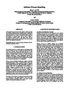
new state that needs to be set in any instance of the data element for which the timer expires. The need for the first two elements can be straightforwardly derived, the third element is introduced because of its omnipresence in contemporary business processes. The control flow model of such a process flow is based on the following three primitives: • Trigger states: Every instance of the target or argument data element needs to have a state field or attribute. This persistent field will always keep track of the current position of that data element instance in the control flow. It represents which operations have already been performed on that instance of the data element that is being processed. • State transitions: A processing step or operation on an instance of a data element is specified as a state transition. Performing an operation is represented in the control flow model as a transition from one state—a value of the described state field—to another. In order to allow branching, such a state transition can in general have two outcomes. • Transition actions: A state transition corresponds to the execution of an actual operation on that instance of the data element. Such transition action performs a real operation, and is implemented in a so-called action element. III. M APPING M ETHOD C ONSTRUCTION The construction of the mapping method will be illustrated using a generic business process example of a make to order producing company. Figure 1 represents the process description modelled in BPMN. It should be mentioned that the business process example has a rather restricted scope, and can thus only be considered as a proof-of-concept to exemplify the applicability of the proposed mapping method. A small company manufactures customized bicycles. When an order for a customized bicycle is received by the organization, it is first evaluated by the sales department. If the order is rejected, the customer is notified and the process
2010, © Copyright by authors, Published under agreement with IARIA - www.iaria.org
International Journal on Advances in Software, vol 3 no 1 & 2, year 2010, http://www.iariajournals.org/software/
60
Figure 1.
BPMN business process model
ends. If it is accepted, both the warehouse and production are informed. Production is commanded to plan and prepare the assembly. The warehouse processes the required items by checking the availability of the parts. If the items are available in-house, they are reserved; otherwise the items are back-ordered. Upon arrival of the ordered items, they will be received and reserved. When all required items are available and the assembly is prepared, the order is produced. After production, the order is passed to the shipping department that will ship the bicycle to the customer. When the order has not been completed within six weeks, the customer will be contacted. This option is incorporated to offer the customer the opportunity to cancel or change and resubmit the order. In a first subsection, it will be discussed how data elements will be derived from the model. In a second subsection, the identification of flows, constituent tasks and action elements will be described. A third subsection will provide a summary on the
proposed way of working, and thus constitutes a first draft of the resulting method. A. Data Elements Based upon the theorems of separation of concerns and data version transparency, business entities and business actors are analyzed if they correspond to separate data elements. For every noun represented in the BPMN model, expressing an business entity or actor, it should be decided whether it indicates an entity, an instance of an existing entity, or an attribute describing an existing entity. In this way, the identification is rather similar as searching for business objects within objectorientation. The choice is however not irreversible as introducing a new separate data element and an additional flow regarding this data element, is a functional change that can be translated in a set of anticipated changes for which Normalized Systems exhibit proven evolvability [15]. Determining data elements representing the life cycle objects on which the process flow is executed, can however be considered to be more concise. As business processes symbolize a sequence of activities on one or more business entities, the life cycle entities are rec-
2010, © Copyright by authors, Published under agreement with IARIA - www.iaria.org
International Journal on Advances in Software, vol 3 no 1 & 2, year 2010, http://www.iariajournals.org/software/
61
ognized as the elementary artefacts, i.e. concerns, passing through the different states. Because of the relatedness to the information-centric business process modelling approach, research results from that domain can, to some extent, be incorporated in our work. As such, three conditions to determine whether an information entity is a business entity were identified [3, p.290]: • business entities are records storing information pertinent to a given business context; • business entities have their own, distinct life cycle from creation to completion; • business entities have a unique identifier within the organization. Applying our insights complemented with the aforementioned guidelines leads to the identification of the following data elements. A first data element is of course the User: all actors in the description need to be defined as users of the information system. In general, this data element is already in existence for other business processes that have previously been automated, as a user symbolizes a generic concern in all information systems. Also the criteria mentioned by the related research apply, as a User has a distinct life cycle and a unique identifier. This also accounts for a Customer data element, probably linked to the User element, as a Customer has its distinct life cycle and unique identifier within the organization. It should be mentioned that, according to Normalized Systems theory, the introduction of one or more additional data attributes to an existing data element can be done with a limited impact [16]. There are two main life cycle data elements in the described business process or flow: the Order and the Part. Although the business process in Figure 1 is described as a unified process of Order and Part, the actions on these entities cannot be represented by the same flow because they can clearly evolve independently from each other, and are thus different concerns. Moreover, the two elements have obviously independent life cycles. An instance of the Order data element is created by the customer and goes through the various processing steps that have been described, ending with the shipment or delivery of the order. For every part
that makes up the specific instance of a product, an instance of the Part data element is created, and linked to the instance of the respective Order data element. Every individual instance of the Part data element goes through its own life cycle of reservation, reception, and so on. The observations that different information is stored and that different identifiers are used to pinpoint an Order and a Part, add to the rationale to identify these data elements. Several tasks that are described in the process involve some kind of notification. Such a notification clearly consists of two concerns: the extraction of the information that makes up the message’s content on the one hand, and the actual sending of the message on the other. This means that, in accordance with separation of concerns and separation of states, they have to be separated into two different tasks or action elements. The second task is actually quite a generic one: the sending of a notification message, such as an e-mail or SMS. Therefore, it should operate on a corresponding generic target data element Notifier, in a corresponding separate flow. This also implies that the first task of such a composed notification task will be implemented as a bridge action. Based on the appropriate information extracted from the order state, an instance of the Notifier data element will be created. B. Flows, Tasks and Action Elements This paragraph discusses how flows, tasks and the diverse kinds of action elements will be detected. A number of recommendations and guidelines with their rationale will be provided, each of them illustrated by the representative examples within the scope of our case example. It should be repeated that based upon the four Normalized Systems’ theorems, workflow elements are represented by state transition diagrams of a single data element; and action elements will contain only one functional task resulting in a state transition of the life cycle data element driving the flow. The resulting state transition diagrams of the elementary life cycle data elements Part and Order can be found in Figures 2 and 3 respectively.
2010, © Copyright by authors, Published under agreement with IARIA - www.iaria.org
International Journal on Advances in Software, vol 3 no 1 & 2, year 2010, http://www.iariajournals.org/software/
62
Figure 3.
Schematic representation of the Order state transition diagram.
to be sent. A best practice is therefore to provide each state with a distinctive, self-explanatory label.
Figure 2. diagram.
Schematic representation of the Part state transition
1) State labelling: The figures illustrate that due to separation of states, the different states must be explicitly defined. Moreover, this state definition has to be very concise because every defined state has to be unique for the life cycle object driving the flow. Otherwise, the action element triggered by the respective state can not be determined as it is not clear which state the life cycle object has. For example, an order can be rejected at multiple points in the flow, either by the sales department when receiving the order, or by the customer when the order takes longer than six weeks to complete. If these rejection states would be both labelled rejected, it would not be possible to distinguish between the two different notifications that have
2) Interacting life cycle data elements: Certain life cycle data elements will be created as a result or as a consequence of actions performed by other life cycle data elements. Based on the Normalized Systems theorems separation of concerns and separation of states, these two life cycle data elements are not the same concern and both life cycles should be separately managed. Within paragraph II-B2, a bridge action was mentioned as one of the types of action elements. This action element will be used when a second life cycle data element has to be initiated. Following examples will exemplify the way of working. Concerning the Part Processor, it was mentioned in Section III-A that the Part data element is identified as a separate life cycle element, and therefore Part Processor is a bridge action because at this point in the process, an instance of the Part life cycle data element is created for every single part of the order. Handling the Item Processing subprocess exemplified in Figure 1 is clearly another concern than handling the complete order. It should also be mentioned that abstraction is made of the Prepare Assembly activity mentioned in Figure 1. This ac-
2010, © Copyright by authors, Published under agreement with IARIA - www.iaria.org
International Journal on Advances in Software, vol 3 no 1 & 2, year 2010, http://www.iariajournals.org/software/
63
tivity probably consists of planning the production, reserving the needed resources, etcetera. In this sense, it is argued that this activity is most likely a bridge action to an additional workflow element, for instance a ProductionPlanningFlow. The final step of the Order flow consists of shipping the order to the customer: a bridge action will create a shipment data element that will go through the shipping process not further explained in this paper. The Part Orderer within Figure 2 is a bridge action to another flow or information system, as purchase orders will probably be handled by a PurchaseFlow. Based on the Normalized Systems theorems separation of concerns and separation of states, the issue of purchase orders being delivered on time, with the correct amount, etcetera. is not an issue of the PartFlow, but of a PurchaseFlow. 3) Notifying stakeholders: Like already mentioned at the end of Section III-A, business processes often require activities to notify certain stakeholders. This requirement is actually a particular case of interacting life cycle data elements, as one is always an instance of the Notifier data element. Based upon the theorem separation of concerns, sending notifications to diverse stakeholders is considered a separate concern. Delivering a message in the correct format to the intended recipients at the right time, with the related fault handling, does not concern other data elements. Our solution consists of implementing a bridge action that will trigger the creation of a Notifier data element. Of course these bridge actions will differ from each other, as the semantics of the message that has to be communicated, vary depending on the situation. Therefore, the bridge action will pass a set of parameters defining the message’s content and format. Additional tasks that should be performed to send the notifications, can be designed using workflow elements defined upon the Notifier data element. In the example, notifiers can be found at diverse points within the Order workflow represented by Figure 3. First, when receiving an order, a notification is sent to a sales representative in order to evaluate the order. The Sales Notifier
bridge action will thus result in the creation of a Notifier data element that sends an e-mail to a sales representative stating that a particular order has to be evaluated. Second, the Department Notifier bridge action creates a notification or assembly preparation request that is sent to the manufacturing department, and the individual parts are created. Third, when the six weeks timer elapses, a Delay Notifier bridge action is triggered that will create a notification sent to the customer to inform her about the delay and to request the wanted action. The multiple notifiers illustrate the usefulness of isolating a change driver in its designated data element to obtain true reusability as notification functionality can thus be reused by applying a bridge action. 4) Communicating life cycle data elements: Different life cycle data elements sometimes need to communicate their state to one another in order to trigger further execution of the flow. Although in many cases an external action can implement this, like the Order Assembler action in the OrderFlow or the Part Receiver action in the PartFlow, this will not suffice in the particular case when a life cycle data element A triggers multiple instances of another life cycle data element B, and its flow can only continue when all these instances have reached a particular state. In this case, an action element on the triggering life cycle data element A has to be implemented that will verify the state of the initiated instances of B. When all the initiated instances of B reach the target state, the action will set off the state transition on A. If one of the triggered instances of B has not yet arrived at the target state, A’s state will not be altered. As such, the action element will be initiated until all instances of B attain the target state. An example from the case will exemplify and further ground the proposed solution: when all parts are created in the OrderFlow, the order has to wait until it can be produced. This implies that the manufacturing department is ready to start the assembly, and that all parts are reserved and available in stock. Actually, both these conditions will become available in the instance
2010, © Copyright by authors, Published under agreement with IARIA - www.iaria.org
International Journal on Advances in Software, vol 3 no 1 & 2, year 2010, http://www.iariajournals.org/software/
64
of the Order data element, either through a data attribute or data links. Therefore, though this information will be entered by another flow (e.g. the PartFlow) and due to the separation of concerns theorem not allowing one flow to actively interfere with another one; a simple standard action, Assembly Readiness Checker, is needed to check the appropriate information on a regular basis. A flow element actively interfering with another flow element can be considered a so-called GOTO statement. Although most contemporary business process descriptions and languages do not inhibit this behaviour, Normalized Systems theory does not allow their presence in accordance with the seminal work of Dijkstra [8]. The reason why Assembly Readiness Checker is positioned in the OrderFlow, and not within the PartFlow, is quite straightforward as the Order instance “knows” through its data links, which Parts are created. Therefore, an action in the PartFlow communicating that everything has completed correctly for a particular part can not be implemented as there are multiple parts for a single order and the individual Part instances are not aware of the existence of the other instances. 5) Human tasks: Whether a task is executed by a human or an information system does actually not matter, as it is the encapsulated functional task representing the change driver that should be isolated within its designated action element. When defining the action element within paragraph II-A, it was derived that an action element encapsulates one and only one functional task. The way in which this task is performed, manually or automated, is just a matter of implementation and should, adhering to the action version transparency theorem, be kept hidden from the action or flow calling the respective action element. For instance, it is obvious that Order Evaluator within Figure 3 is a manual action: the sales manager verifies the order and takes a decision whether or not to accept the order. This task is not identified as a separate element because of being performed manually, but because it represents a separate concern, namely an elementary functional task, and because the task
triggers a state transition relevant to the life cycle of the underlying Order data element. 6) Timer functionality: Contemporary business processes very often contain time constraints, e.g. stakeholders only have a given period to answer, a management reporting process should be run every morning at 7 AM, etcetera. Because of its omnipresence and its clear concern, a time constraint, a timer element was introduced in paragraph II-B3 to represent this functionality. Adhering to the Normalized Systems’ theorems, such a timer element can only operate on a single life cycle data element and will specify a maximum allowed period between two states of the associated data element. As such, the start state will probably trigger two elements: the action element that is described within the flow element, and the timer element. When the timer expires, either a new state is set in an instance of the data element, or a specific action element is triggered. The description of the OrderFlow process specifies a timer of the second kind. When an order takes longer than six weeks to be completely processed, the customer has to be contacted. This individual timer element, schematically represented in Figure 3 by the open circle and described in Table I, has an allowed time window of six weeks between start state accepted and target state assembled before the Customer Delay Notifier bridge action is potentially triggered. The start state accepted thus triggers both the timer element Customer Delay Timer and the bridge action Department Notifier. 7) Cancellation Pattern: Within the business process, a customer contact was provided to offer the customer the opportunity to cancel his order. However, one should be very cautious with possible cancellations. If the customer decides to cancel the order, the state cannot simply be set to cancelled and thus disregard everything that has already been done. This would very quickly lead to an infinite amount of parts in stock as these parts will be kept reserved for an already cancelled order. If it is absolutely necessary to offer the customer the pos-
2010, © Copyright by authors, Published under agreement with IARIA - www.iaria.org
International Journal on Advances in Software, vol 3 no 1 & 2, year 2010, http://www.iariajournals.org/software/
65
Start state accepted
Target state assembled
Timer Element Name Customer Delay Timer
Time elapse 6 weeks
Action Element Triggered Customer Delay Notifier
Table I T IMER ELEMENT OF O RDER FLOW
sibility to cancel the order, an entire branch should be added to the process flow of the order, where the assembly request is withdrawn and the various reserved parts are released. Within our example, only the Part Releaser action element was modelled, because no details were provided what should be performed when the customer cancels its order. The Part Releaser is a standard action sending a release request to the Part data element, which will handle the request accordingly. However, contemporary organizations need to provide the customer an opportunity to cancel an order during a part of or even the whole process. By consequence, cancel requests can arrive not only on specified moments like discussed above, but also during the regular flow execution. Like mentioned in paragraph III-B4, the Normalized Systems’ theorems do not allow to directly interrupt a flow and to change the state. Due to transactional integrity reasons, flows can only be routed by elementary action elements resulting in state transitions of the underlying data element. To support this cancellation functionality, we suggest to add a cancelRequest data attribute to every data element representing a business artefact that might be have to cancelled. The following cancellation pattern describes how to handle such a cancel request: •
Capture
cancel
request
by
updating
cancelRequest data attribute. Conditions
•
•
that check whether the cancel request is valid, are designed in the update operation of this data attribute. The engine supporting the flow element then checks the cancelRequest data attribute, equivalent to the way it verifies the different states of the different data elements to trigger the correct action element. If the cancelRequest data attribute’s state is true, the regular state field is updated to a value
•
such that the regular flow does not continue; and the state field in which the data element was before cancelling, will be stored in another state attribute of the respective data element. This second state attribute will be referenced in our approach as a parking state field. The value attributed to the regular state attribute must be the same for every data element, as this will uniquely define the situation and can thus be recognized within all data elements; as such we suggest to label it cancel requested. The second state attribute (see also paragraph III-B8) is necessary to trigger the correct actions to handle the cancellation. The way a cancellation will be handled, evidently varies according to the data element’s life cycle state. For instance, cancelling an accepted order will be totally different compared to cancelling an already produced order. Finally, an action element will be triggered that based upon the value of the parking state field will decide which cancellation flow should be triggered as the scenario will differ according to the actions already executed upon the data element that was requested to be cancelled. The output of this action element is attributing a value to the regular state field of the particular data element that uniquely describes which action should be triggered to initiate the correct cancellation flow.
If the customer decides to confirm the order, the process can simply continue, and should of course not be restarted, nor should it re-create the various parts. This latter option will be discussed in the next paragraph. 8) Pausing flows: When the customer is contacted to either cancel or resubmit the order, it can be argued that a third option is missing: the
2010, © Copyright by authors, Published under agreement with IARIA - www.iaria.org
International Journal on Advances in Software, vol 3 no 1 & 2, year 2010, http://www.iariajournals.org/software/
66
customer still wants its initially ordered bicycle to be delivered. In this case, the order has to continue its regular flow. In the BPMN model however, this behaviour is difficult to model as neither the interrupting nor the non-interrupting intermediate events added in the latest proposed BPMN standard version 2.0 [18], exhibit the wanted behaviour of “pausing” the flow until the customer answer is received. Interrupting intermediate events break off the flow, and non-interrupting intermediate events let the flow continue. The Normalized Systems’ theorems and derived primitives do however enable this desired behaviour in a quite straightforward and easy to comprehend way: preserve the life cycle data element’s state in the parking state data attribute. The way of working will be explained by applying it to the example case, in particular when the Customer Delay Notifier discussed in paragraph III-B6 elapses and the customer will be notified. As a result, the Order data element’s state will become customer delay notified. The state in which the Order data element was before the timer elapsed should however not be neglected as it might be possible that the customer requests the continuation of the initial order. Therefore, this state should be made be persistent by storing it in the designated parking state data attribute. In this way, the flow will be paused and can be reinstated upon request by retrieving the state from the parking state data attribute and updating the regular state field with this value. The fact that this requirement can be solved in a rather simple way is due to the deterministic nature of the Normalized Systems’ theory. First, the separation of concerns theorem prescribes that atomic functional tasks should be separated in different action elements. Second, the separation of states theorem adds the need of defining action states in order to isolate these individual tasks. Third, combining the two theorems leads to our proposition that business processes should be implemented as state machines operating on a single data element. Fourth, adding the state labelling guideline discussed in paragraph III-B1 to these characteristics realizes that any business process
state will be uniquely and unambiguously defined by the state field of the life cycle data element going through the process flow. Fifth, the deterministic pattern expansion used to design and implement Normalized Systems’ elements makes it possible to introduce such an additional state field in a standard way to any instance of the respective data elements. Sixth, as such the initial life cycle data element’s state can persistently be stored and retrieved upon request without interfering with the prerequisite of transactional integrity. C. Method Overview To summarize the results when obeying to the guidelines discussed above, Tables II and III represent the flow elements driving the business process. In the first section, the limited potential for verification was mentioned as one of the drawbacks of contemporary business process languages. When comparing the business process represented as Normalized Systems elements in Figures 2 and 3, to the BPMN of Figure 1, it can be noticed that the former representations offer better support for verification as process states are explicitly modelled, and can thus be compared with the allowed state transitions of the underlying data element. We also claim in accordance with Kumaran et al. [12, p.41] that representing processes as state machines of life cycle data elements (or business entities) increase the understandability of these models. It can be concluded that applying the Normalized Systems’ theorems on business processes already provides some principles to assess these business processes. In this sense, the following preliminary guidelines are proposed in this article: • Business processes should be separated in workflow elements driven by the persistent state field of a single life cycle data element. • These life cycle data elements are identified as the elementary artefacts passing through the different states during business process execution, e.g. Order. Useful conditions to identify such life cycle data elements are found in the work regarding business entities [3, p.290]. • Time constraints should be isolated in separate timer elements, e.g. a six weeks timer.
2010, © Copyright by authors, Published under agreement with IARIA - www.iaria.org
International Journal on Advances in Software, vol 3 no 1 & 2, year 2010, http://www.iariajournals.org/software/
67
Start State created sales-notified not-accepted accepted departments-notified processing-parts ready-for-assembly assembled customer-delay-notified rejected
End State sales-notified accepted XOR not-accepted refusal-notified departments-notified processing-parts ready-for-assembly assembled shipped rejected cancelled
Action Element Name Sales Notifier Order Accepter Customer Reject Notifier Department Notifier Part Processor Assembly Readiness Checker Order Assembler Order Shipper Customer Decider Part Releaser
Action Element Type Bridge Manual Bridge Bridge Bridge Standard External Bridge Manual Bridge
Table II S TATE TRANSITIONS DESCRIBING O RDER WORKFLOW ELEMENT
Start State created not-available ordered available
End State available XOR not-available ordered available reserved
Action Element Name Part Checker Part Orderer Part Receiver Part Reserver
Action Element Type Standard Bridge External Standard
Table III S TATE TRANSITIONS DESCRIBING PART FLOW ELEMENT
•
•
•
When the creation of a life cycle data element is dependent on actions performed by another life cycle data element, the interaction between the two elements has to be implemented using a bridge action. Frequently required generic functionality like notifying people, should be isolated in separate workflow elements driven by a generic data element, e.g. Notifier. Separating the activities of a business process into different tasks and action elements can be done in a structured way by dividing different concerns, representing different change drivers, into different Normalized Systems primitives. For instance, the identification of the action element Assembly Readiness Checker based upon the communicating life cycle data elements guideline, exemplifies the fact of only allowing one functional task in one single action element: some designers might be tempted to implement this task either in the workflow element itself, or in the PartsCreator action element.
•
•
To cancel processes, a Cancellation Pattern is proposed needing a cancelRequest and a parking state field data attribute that are by default provided in every life cycle data element. To enable processes to be paused, a pattern is proposed again using the by default provided parking state field data attribute. IV. R ELATED W ORK
Our work relates to research in three areas. First, it is related to research on modularity and stability. Modularity expresses the idea to decompose a system in loosely coupled building blocks. In software engineering, modularity is used to decompose an information system in independent modules [19]. Stability refers to the systems theoretic notion that a bounded input results in bounded output. Although no precise definition exists in the context of information systems, most authors imply it to refer to software or information systems architectures designed to be resistant to change propagations [10]. Second, two business process theorems relate to
2010, © Copyright by authors, Published under agreement with IARIA - www.iaria.org
International Journal on Advances in Software, vol 3 no 1 & 2, year 2010, http://www.iariajournals.org/software/
68
a certain extent to our viewpoint. First, the case handling paradigm also focuses on the role of data objects to drive the flow [22]. This orientation considers a case to be the central concept and describes it as a product, which is produced with structure and state. This structure and state are based on a collection of data objects representing valuable information about the case. As such, a process is defined as the recipe for handling cases of a certain type. The main differences with other workflow approaches are the focus on the whole case and not on single work-items; and the state of the case, rather than the control flow, that primarily determines which activities are enabled [23]. Second, our work is related to the information-centric approach on business process modelling where a business process is modelled as the interacting life cycles of information entities [12]. These information entities, also called business entities, are used to describe business processes operating as state machines where state transitions are caused by activities acting on the most important entity. Business processes are thus defined as the life cycles of the business entities from their initial to final state. In this sense, the approach is very closely related to ours. Third, the mapping method presented in this paper relates to research in the Service-Oriented Architectures (SOA) domain. In this domain, a number of approaches exist that describe how to identify service operations based on business process models. These approaches originate from both practice, e.g., Mainstream SOA Methodology [5], and academia, e.g., [6]. A more comprehensive overview can be found in [11], [20]. Because our proposed method is based upon proven software engineering principles, it mainly relates to the principles-driven design approaches [20]. V. C ONCLUSION
AND
F UTURE W ORK
When deriving Normalized Systems’ primitives from business process models, the following initial conclusions can be drawn. Data elements are mostly only indirectly represented within business process models. Therefore, every noun should be systematically checked as a potential data element
candidate. The identification of the elementary life cycle data elements is however considered relatively straightforward as they represent the business entities going through different business states during business process execution. Moreover business processes will potentially be enabled by multiple workflow elements as the Normalized Systems theorems propose that a workflow element should only relate to one and only one data element. In this sense, both Order and Part workflow elements were identified. Due to the fact that business process models emphasize the flow of activities, the constituent tasks of these workflow elements can be deducted in a structured way. Also action elements are obtainable by merging the Normalized Systems’ laws with the functionality exhibited by the activities within the business process model. For instance, timer elements are basic blocks of both business processes and Normalized Systems, and can therefore be mapped in a structured way. In addition, the case demonstrated how the omnipresent tasks of contacting diverse actors can be mapped to a generic Notifier data element on which workflows taking care of the requested notification functionality can be defined. Our future work will be, next to executing more extended and additional case studies, targeted at formalizing the method proposed in this paper. The rather implicit rules must be translated into strict guidelines, providing an unambiguous way to derive the Normalized Systems elements from business process models. This will also include identifying the different concerns existing at the level of business processes, as they will vary from the concerns identified at the software level. Second, the mapping of other business process modelling languages and enterprise architecture descriptions to Normalized Systems primitives will be studied. Finally, research on the Normalized Systems theory itself will be extended. Key areas are the introduction of additional supporting tasks into the stable software elements, and porting the stable element patterns to supplementary software platforms.
2010, © Copyright by authors, Published under agreement with IARIA - www.iaria.org
International Journal on Advances in Software, vol 3 no 1 & 2, year 2010, http://www.iariajournals.org/software/
69
R EFERENCES [1] D. Van Nuffel, H. Mannaert, C. De Backer and J. Verelst, “Deriving Normalized Systems elements from business process models,” in Proceedings of Fourth International Conference on Software Engineering Advances (ICSEA 2009), K. Boness, Ed. Los Alamitos, CA, USA: IEEE Computer Society, September 2009, pp. 27–32. [2] C. Y. Baldwin, and K. B. Clark, “Design Rules: Vol. 1: The Power of Modularity,” MIT Press, Cambridge, MA, USA, 2000. [3] K. Bhattacharya, C. Gerede, R. Hull, R. Liu, and J. Su, “Towards formal analysis of artifact-centric business process models,” in BPM 2007, ser. Lecture Notes in Computer Science, G. Alonso, P. Dadam, and M. Rosemann, Eds., vol. 4714. Berlin Heidelberg: Springer-Verlag, 2007, pp. 288–304. [4] M. De Backer, M. Snoeck, G. Monsieur, W. Lemahieu, and G. Dedene, “A scenario-based verification technique to assess the compatibility of collaborative business processes,” Data and Knowledge Engineering, vol. 68, no. 6, pp. 531– 551, June 2009. [5] T. Erl, “SOA: Principles of Service Design,” Prentice Hall, Upper Saddle River, NJ, USA, 2008. [6] A. Erradi, S. Anand, and N. Kulkarni, “SOAF: An Architectural Framework for Service Definition and Realization,” in Proceedings of the IEEE International Conference on Services Computing (SCC’06). Los Alamitos, CA, USA: IEEE Computer Society, September 2006, pp. 151–158. [7] R. Dijkman, M. Dumas, and C. Ouyang, “Semantics and analysis of business process models in BPMN,” Information and Software Technology, vol. 50, no. 12, pp. 1281–1294, November 2008. [8] E. Dijkstra, “Go to statement considered harmful,” Communications of the ACM, vol. 11, no. 3, pp. 147–148, 1968. [9] S. G. Eick, T. L. Graves, A. F. Karr, J. Marron, and A. Mockus, “Does code decay? Assessing the evidence from change management data,” IEEE Transactions on Software Engineering, vol. 27, no. 1, pp. 1–12, January 2001. [10] D. Kelly, “A study of design characteristics in evolving software using stability as a criterion,” IEEE Transactions on Software Engineering, vol. 32, no. 5, pp. 315–329, May 2006. [11] A. Kontogogos, and P. Avgeriou, “An Overview of Software Engineering Approaches to Service Oriented Architectures in Various Fields,” in Proceedings of the 18th IEEE International Workshops on Enabling Technologies: Infrastructures for Collaborative Enterprises, S. M. Reddy, Eds., Los Alamitos, CA, USA: IEEE Computer Society, July 2009, pp. 254–259. [12] S. Kumaran, R. Liu, and F. Y. Wu, “On the duality of information-centric and activity-centric models of business processes,” in 20th International Conference on Advanced Information Systems Engineering, CAiSE 2008, ser. Lecture Notes in Computer Science, Z. Bellahsene and M. Leonard, Eds., vol. 5074. Berlin Heidelberg: Springer-Verlag, June 2008, pp. 32–47. [13] M. M. Lehman, “Programs, life cycles, and laws of software evolution,” in Proceedings of the IEEE, Vol. 68, pp. 1060–1076, September 1980.
[14] M. M. Lehman and J. F. Ramil, “Rules and tools for software evolution planning and management,” Annals of Software Engineering, vol. 11, no. 1, pp. 15–44, November 2001. [15] H. Mannaert and J. Verelst, Normalized Systems: Recreating Information Technology Based on Laws for Software Evolvability. Hasselt: Koppa, March 2009. [16] H. Mannaert, J. Verelst, and K. Ven, “Exploring the concept of systems theoretic stability as a starting point for a unified theory on software engineering,” in Proceedings of Third International Conference on Software Engineering Advances (ICSEA 2008), H. Mannaert, T. Ohta, C. Dini, and R. Pellerin, Eds. Los Alamitos, CA, USA: IEEE Computer Society, October 2008, pp. 360–366. [17] H. Mannaert, J. Verelst, and K. Ven, “Design theorems for avoiding combinatorial effects in integrating open source software components in software product lines.,” in Proceedings of the Joint Workshop on Quality and Architectural Concerns in Open Source Software (QACOS) and Open Source Software and Product Lines (OSSPL), Babar, Muhammad Ali et al. Eds. Sk¨ovde, Sk¨ovde University, 2009, p. 20-27. [18] Object Management Group, “Business Process Modeling and Notation, v2.0 Beta 1 OMG Adopted Beta specification,” online available at: http://www.omg.org/cgibin/doc?dtc/09-08-14, August 2009. [19] D. Parnas, “On the Criteria To Be Used in Decomposing Systems into Modules,” in Communications of the ACM, Vol. 15, Nr. 12, pp.1053–1058, 1972. [20] S. Patig, “Cases of Software Services Design in Practice,” in ICSOFT 2009 - Proceedings of the 4th International Conference on Software and Data Technologies, B. Shishkov, J. Cordeiro, and A. Ranchordas, Eds. Setubal, Portugal: INSTICC Press, July 2009, pp. 376–383. [21] J. Recker, “Opportunities and constraints: the current struggle with BPMN,” Business Process Management Journal, vol. 16, no. 1, pp. 181–201, 2010. [22] H. A. Reijers, J. H. M. Rigter, and W. M. van der Aalst, “The case handling case,” International Journal of Cooperative Information Systems, vol. 12, no. 3, pp. 365– 391, September 2003. [23] W. M. P. van der Aalst, M. Weske, D. Gr¨unbauer, “Case handling: a new paradigm for business process support,” Data and Knowledge Engineering, vol. 53, no. 2, pp. 129– 162, May 2005. [24] M. Weske, Business Process Management: Concepts, Languages, Architectures. Springer-Verlag, 2007. [25] B. J. Williams and J. C. Carver, “Characterizing software architecture changes: A systematic review,” Information and Software Technology, vol. 52, no. 1, pp. 31–51, January 2010. [26] J. L. Zhao, M. Tanniru, and L.-J. Zhang, “Services computing as the foundation of enterprise agility: Overview of recent advances and introduction to the special issue,” Information Systems Frontiers, vol. 9, no. 1, pp. 1–8, March 2007.
2010, © Copyright by authors, Published under agreement with IARIA - www.iaria.org