Informal description (UML and text) of design patterns is adopted to facilitate their understanding by software developers. However, these descriptions lead to ...
Towards a Formalization of Real-Time Patterns-Based Designs Kamel Boukhelfa(�) and Faiza Belala Department of Software Technologies and Information Systems, Faculty of New Information Technologies and Communication, University of Constantine 2, Ali Mendjeli, Algeria {kamel.boukhelfa,faiza.belala}@univ-constantine2.dz http://www.univ-constantine2.dz
Abstract. Informal description (UML and text) of design patterns is adopted to facilitate their understanding by software developers. However, these descriptions lead to ambiguities, mainly when we consider Real time Design Patterns that deal with critical problems encountered in the design of real-time systems. Hence, there is a need for formal specification of the DPs and RTDPs to insure their successful application. In this paper, we propose a formalization approach of the system design based on real-time patterns (RTDPs). The processes of instantiation and composition of design patterns, permit us to generate design models (structural and dynamic) of complex systems. The resulting designs are represented in UML-MARTE profile to express the temporal properties and constraints. The algebraic specifications (in Maude language) become more natural and more efficient.
1
Introduction
A design pattern expresses solution of a known and recurrent problem in a particular context [5]. Design patterns are applied in object programming software to improve the quality of the resulting system. The reuse concept is also important in the development of real-time and embedded systems. Thus, design patterns can be used to capture the experience and allow the reuse of the ”good” solutions to resolve the problems encountered during the design process of such systems [3]. Intuitively, the term ”real-time” refers to design patterns those dealing with the temporal aspects of systems, whereas this is not always the case. Indeed, realtime design patterns deal with the general problems encountered in the design of real-time systems (that may be or not related to the time) such as synchronization or memory allocation. The real-time design patterns vary according to their areas of application and according to the design approaches. Generally, design patterns and also real-time design patterns were described, until now, by using a combination of textual descriptions, object oriented graphical notations such as UML diagrams and sample fragments of code [5], [3]. This informal description of design patterns is adopted to facilitate their understanding by software developers. However, formal specifications provide a precise and rigorous description for better understanding patterns and their instantiation and composition. This c IFIP International Federation for Information Processing 2015 � A. Amine et al. (Eds.): CIIA 2015, IFIP AICT 456, pp. 624–635, 2015. DOI: 10.1007/978-3-319-19578-0_51
Towards a Formalization of Real-Time Patterns-Based Designs
625
description is then ready for several analysis and verifications upon one or more functional or non-functional properties. Several research work around design patterns deal with issues related to their representation and specification. We distinguish two points of view adopted for this purpose. The first one concerns all works that adopt the meta-modeling approaches and consequently the definition of patterns modeling languages based on UML. These works aim in general to provide solutions for integrating design patterns in CASE tools. The second kind of research work is characterized by the use of the formal methods to specify the design patterns and then provide suitable models to the analysis and verification stages. However, few studies are particularly interested in RTDPs. In this work, we start from the real-time design patterns as the basic models. Through the instantiation and the composition processes, we conceive design models and represent them in UML-MARTE profile [10]. We use Rewriting Logic [9] as a formal foundation for the specification of the Pattern-Based models and thus, we encode in Maude language [2] the formal specification of both parts of those models, namely the structural and dynamic part. The rest of this paper is organized as follows: After recalling the used basic concepts of RT Design Patterns, MARTE profile and rewriting logic via its practical language Maude in section 2, we outline in section 3, how it is possible to give a formal base to real-time systems designs thanks to a judicious coupling of UML-MARTE profile and rewriting theories. Then, in section 4, we describe the formalization approach with Maude’s object-oriented modules, through a realistic example. Finally, we conclude the paper with constructive remarks and future work.
2 2.1
Basic Concepts Real-Time Design Patterns
In object oriented programming, design patterns are considered as a mean to encapsulate the knowledge of experienced software designers and represented it in an understandable form in order to permit its reuse. For each design pattern, are defined the roles of classes, relationships between classes and objects, and how this pattern can be applied to resolve a given problem in a specific context. The structure describing a design pattern mainly includes the name, problem, solution and consequence [3]. RT design patterns are a kind of patterns that have evolved specifically for real-time systems, and they provide various approaches to addressing the fundamental real-time scheduling, communications, and synchronization problems [3]. As a GOF design patterns, RTDPs are represented in UML and the most temporal constraints (especially in the interactions) are expressed in the natural language.
626
2.2
K. Boukhelfa and F. Belala
The UML Profile for MARTE
The UML profile for MARTE (Modeling and Analysis of Real-Time and Embedded systems) is an OMG standard. It provides support for specification, design and verification/validation stages. This new profile is intended to replace the existing UML Profile for Schedulability, Performance and Time [10]. Modelbased design of RTE systems with MARTE proceeds mostly in a declarative way. The users can annotate their models with real-time or embedded concerns using the extensions defined within the HLAM (High-Level Application Modeling) sub-profile (see the next section). The HLAM package provides possibilities of modeling on one hand quantitative features such as deadline, period and, in the other hand, qualitative features that are related to behavior, communication and concurrency. MARTE provide the NFP package (Non-functional Properties Modeling) in order to specify the NFP of properties in a detailed way [10]. 2.3
Rewriting Logic and Maude
Rewriting logic (RL) is known as being the logic of concurrent change, taking into account the state and the concurrent systems calculus. It is shown as a unifying semantic framework of several concurrent systems and models [9]. In RL, a dynamic system is represented by a rewriting theory R = (Σ, E, R, L), describing the complex structure of its states and the various possible transitions between them. The theoretical concepts of the rewriting logic are implemented through the Maude language [9,2] that integrates object oriented programming, used in our formalization to encode the DPs and their meta-models specifications. Maude logical basis gives a clear definition of the object oriented semantics and makes it a good choice for the formal specification of object oriented systems.
3
Formalization Approach Principle
First, we use a given design pattern to generate an UML design (structural and dynamic parts). The resulting design will be enriched by the MARTE notations, namely the concepts defined in HLAM sub-profile, such as RtUnit, PpUnit and Rtfeature, and those defined in the NFP sub-profile, such as NFP_DateTime, NFP_Duration and NFP_Frequency. The second step allows to transcript UMLMarte description to Maude specification. Here, we use Full-Maude, an extension of Maude, that allows us to manipulate the object-oriented concepts, especially objects, classes and attributes. We show in the following sub-sections, how we encode, any system design, described with UML-MARTE and RT Design Patterns coupling, in Maude. 3.1
Static Part
For the structural part, we can note the existence of a correspondence between some concepts of Maude language and UML-MARTE concepts. Unfortunately,
Towards a Formalization of Real-Time Patterns-Based Designs
627
this correspondence is not fully established, there are various concepts in UMLMARTE with no direct equivalent in Maude. The structural part of a design pattern is represented as an UML classes diagram and serves as a model to generate, by means of the instantiation mechanism any structural design based on this pattern. The table 1 contains the MARTE concepts and their correspondences in Maude. For some MARTE concepts without direct correspondence, we also propose their definitions in Maude. For the stereotyping, we define a new class for each stereotype and so, the stereotyped class (in MARTE) is represented by a subclass in Maude. While, for the specification of the methods definition within classes, we define a new sort called Method and we add the declaration of a Maude operation that permits to link each method to its appropriate class (op Methods : class -> SetMethod). In addition, we use the predefined concepts in several modules of Maude such as the SET module, for defining empty and non-empty set (Set, NeSet), and others modules such as BOOL, FLOAT, NAT and STRING to express respectively the types Boolean, Float, Natural and string of characters. Table 1. Correspondence between MARTE and Maude concepts MARTE Concept Class/objet Attribute Directed Association Non-Directed Association Association 1..1/1..*/1..n Composition inheritance
3.2
Maude Concept Class/Oid Attribute Operation Two operation (one for each direction) operation /op − > Set / op − > NeSet (not empty Set) Operation Subclass
Dynamic Part
The dynamic part of a design pattern represents the interaction between different objects instantiated from classes that form a pattern-based design. This part is often represented by a sequence diagram with all the interactions between objects, shown as signals. Firstly, we declare a new sort called Signal that expresses the interaction between two objects. Secondly, we define an operation Instance that represents the objet creation signal. Thus, we can specify all objects related to a given activity execution (represented as sequence diagram). The objects can be declared at the start of this activity (of Oid type) or created during the execution. 3.3
Real-Time Features
MARTE provides Real-time unit concept (RtUnit ) defined in HLAM package. An RtUnit may be seen as an autonomous execution resource, able to handle different messages at the same time. It can manage concurrency and real-time
628
K. Boukhelfa and F. Belala
constraints attached to incoming messages [10]. Any real-time unit can invoke services of other real-time units, send signals or data without worrying about concurrency issues. Another important point to consider when modelling concurrency system is to be able to represent shared information. For that purpose, MARTE introduce the concept of protected passive unit (PpUnit ). PpUnit specify the concurrency policy units either globally for all of their provided services (concPolicy attribute), or locally through the concPolicy attribute of an RtService. We will stereotype the classes as RtUnit or PpUnit regarding their role in the design model. However, operations can be stereotyped as RtService for example. We can add the rtf stereotype at the methods dealing with realtime features such as deadline and reference time. The temporal constraints are expressed in OCL (Object Constrained Language) for instance, a maximum time to perform an activity. For the occurrence kind of a signal (occkind), we define a Maude operation called periodic that permits to identify the nature of this signal appearance (periodically or not). In the case of a periodic signal the periodVal operation is defined to get the value of the period. For the simplicity, we consider the default unit of time (ms). The others elements characterizing a signal are represented in Maude language as operations upon this signal. The temporal constraints represent the conditions on the actions that need to be satisfied, they are expressed in the OCL language (Object Constraints Language). In addition, we define two sorts, Time and Value to specify the temporal variables (eg. triggering instants of signals) and their values. Consequently, it is necessary to have an operation to get the value of an instant t (Rvalue) and a conditional equation to check whether the imposed constraints is verified or not (Satisfy).
4
Running Example: A “Cruise Control System”
This system controls and regulates the speed of a car according to the encountered situations (obstacle, car ahead too closely, etc.). The controller requires the services of three types of sensors, a Speed Sensor, a Laser device to calculate the distance between the car and obstacles and a radar to detect possible obstacles. For simplicity, only the Speed Sensor is considered. 4.1
System Modelling in MARTE
For modelling the system, we use Observer and Sensor patterns and we compose their instances to generate the structural design of the system. The composition is achieved in a simple way, namely through the overlapping of common elements in the two instances. The problem addressed by the Observer Pattern is how to notify some number of clients in a timely fashion of a data value according to some abstract policy, such as ”when it changes,” ”every so often,” ”at most every so often,” and ”at least every so often” [3]. The basic solution offered by the Observer pattern is to have the clients ”subscribe” to the server to be notified about the value in question according the defined policy.
Towards a Formalization of Real-Time Patterns-Based Designs
629
A Speed Sensor is defined as a device that measures or detects a physical phenomenon (temperature, pressure, speed, etc.) and transmits the measure values at real-time to the command ends. The RT-Design pattern Sensor [1] can be specialized as possible types of sensors : Active Sensor, Passive Sensor, Fixed Sensor and Mobile Sensor. We use Active Sensor pattern which is able to send signals Setvalue to one or more objects for modifying the measured value. The class measure stores the data taken by the Sensor, while the attributes (timestamp, validity duration) are used to represent the characteristics of real-time data supported. The class Observed element is used for the physical supervised device description (a wheel for example).
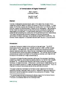
Fig. 1. ”Observer” and ”Sensor” Real-Time Design patterns Structures
Fig. 2. Instances of the ”Observer” and ”Sensor”
For the structural design modelling, we use two instances of the pattern Observer to model the structure of the sub-systems (Speed Controller and Distance Controller). For each sub-system, we need to instantiate Observer and Sensor patterns and so, compose these instances.
630
K. Boukhelfa and F. Belala
We use an instance of Observer pattern to model the Speed Controller subsystem. The resulting model is represented in MARTE and enriched with temporal and NFP proprieties. In the same way, we proceed for modelling Distance Controller sub-system (Fig. 2). Similarly, we use two instances of the Sensor RT-Design pattern (Fig. 2) to model the capturing of the speed rotation of a car wheel, the detection of the possible obstacles in front of a car and the distance measure which separate them from the car (Laser device). The composition of the instances of Observer and Sensor patterns respectively regarding the common elements (the Speed class in first case, and Distance class in the second one) produces the design model of the complete system. In the dynamic
Fig. 3. Structural part of the ”Cruise control system” in MARTE profile
design modelling, we describe the system by using a sequence diagram. This diagram shows a scenario of data acquisition and how the system will react to synchronous or asynchronous events. The interactions that have temporal properties are stereotyped as RtFeature. This allows us to model the temporal behavior of these interactions (occurrence mode, deadline, etc.). MARTE profile also allows us to set time restrictions upon interactions with ”time constraint” (eg. t2-t1 Set{Method} .
The specification of the different associations between classes (undirected association is considered as a two associations, one in each direction) is achieved in the following Maude code. Each association is specified as a Maude operation taking as parameter the first class and as result the second one. The multiplicity is also specified by Set and NeSetsorts for denoting respectively (1..*) and (0..*) multiplicities. --- Associations definition as Maude operation op Speed_Sensor : Speed -> Rotation_Sensor . op Speed_Measure : Rotation_Sensor -> Speed . op Speed_C : Speed_Controller -> Speed . op Notified : Speed_Controller -> Set{Speed_Notify} . op Use_Speed : Speed_Controller -> NeSet{Speed_Client} . --- ... eq Methods(Speed) = getValue . eq Methods(Speed_Controller) = Subscribe Unsubscibe . eq Methods(NotifieV) = getnext .
A dynamic design represented as a sequence diagram and it shows the execution scenario of an activity. In our example, this diagram models the speed/distance capturing activity. The specification of this model is divided in two parts. In the first one, we define all sorts, operations and equations requested for each activity. However, the second is specific for each activity (capturing activity). The important element in this model is the signal. Thus, we define a sort Signal and all temporal features are defined as Maude operations upon it. --- General Specification (classes instantiation and temporal features) sorts Time Signal . vars O : Oid C : class . op Instance : class -> Oid . op operation : Signal -> Method . ops Trigger Targetc : Signal -> Oid . ceq Target(S : Signal) = < O : C | > if operation(S) in Methods(C) . op periodic : Signal -> Bool . op periodVal : Signal -> Float . ceq periodVal(S : Signal) = v : Float if periodic(S) . op Time_ref : Signal -> Value .
Towards a Formalization of Real-Time Patterns-Based Designs
633
op relDl : Signal -> Float . op Rvalue : Time -> Float . --- A capturing (Speed and Distance) activity. Vars Cruise_C Speed_C Distance_C Notify_Sp Notify_D Sp Dis Rot_Sens Las : Oid . eq Instance(Cruise_Controller) = < Cruise_C | isDymamic : false ismain : false poolsize : 10 > . eq Instance(Speed_Client) = < Speed_C | isDymamic : false ismain : true poolsize : 10 main : Speed_Subscribe > . eq Instance(Distance_Client) = < Speed_C | isDymamic : false ismain : true poolsize : 10 main : Distance_Subscribe >. eq Instance(Speed_Notify) : Notify_Sp . eq Instance(Distance_Notify) : Notify_D . eq Instance(Speed) = < Sp | concpolicy : garded > . eq Instance(Distance) = < Dis | concpolicy : garded > . eq Instance(Rotation_Sensor) = < Rot_Sens | isDymamic : false poolsize : 10 > . eq Instance(Laser) = < Las | isDymamic false poolsize : 10 > .
An algebraic semantic is associated to the Signal term GETVALUE_S through the following equations. var t1 : Time . op GETVALUE_S : -> Signal . eq operation (GETVALUE_S) = eq Trigger (GETVALUE_S) = eq Target (GETVALUE_S) = eq Time_ref (GETVALUE_S) = eq periodic (GETVALUE_S) = eq periodVal(GETVALUE_S) = eq relDl (GETVALUE_S) =
getValue . Speed_C . Sp . t1 . TRUE . 20 . 3.3 .
Some rewriting rules are added to Maude specification in order to manage temporal constraints. The following Maude declarations express the essential part. msg Speed_Subscrib_Call : Oid Oid -> Msg [ctor] . msg Distance_Subscrib_Call : Oid Oid -> Msg [ctor] . vars C S Not_C : Oid . op Speed_Subscrib_Signal : -> Signal . eq operation(Speed_Subscrib_Signal) = Speed_Subscibe . eq Trigger (Speed_Subscrib_Signal) = Cruise_C . eq Target (Speed_Subscrib_Signal) = Speed_C . Speed_Subscrib_Call (Cruise_C , Speed_C) . rl[Speed_Sub] < C : Cuise_Controller > < S : Speed_Controller > Speed_Subscrib_Call => < C : Cuise_Controller > < S : Speed_Controller > < N : Speed_Notify > . --- To ensure that a time constraint is verified msg satisfy : Signal Signal Float -> Bool . crl [ satisfy ] satisfy ( S1 : Signal , S2 : Signal , T : Flaot) if Rvalue( (Time_ref(S2) + reldl(S2)) - Time_ref(S1)) < T . Satisfy(GETVALUE_S , GETNET_S , 5) .
634
5
K. Boukhelfa and F. Belala
Discussion and Conclusion
In the literature, we can find several work on meta-modelling approaches to define languages for design patterns. These works are in general based on UML and they aim to define a common model to all patterns in order to integrate them in CASE tools for assisting the designers (code generation or detection of patterns within a design for example). Here, we can cite DPML (Design Pattern Modeling Language)[8] which defines a meta-model and a notation for specifying design pattern solutions and solution instances within object models. In the same context, Dae-Kyoo Kim et al. [7] present an UML-based pattern specification language called the role-based metamodeling language (RBML), allowing to support the development of precise pattern specifications that can be used for the development of pattern tools. In the context of the formal specification, we can cite two significant works namely, the BPSL (Balanced Pattern Specification Language) [11] and LePUS (LanguagE for Patterns Uniform Specification) [6], they aim to formalize the structural and behavior aspects of design patterns. BPSL uses a subset of firstorder logic (FOL) to formalize structural aspect of patterns, while the behavioral aspect is formalized in TLA (Temporal Logic of Actions). LePUS is a fragment of the monadic high-level order logic using a limited vocabulary of entities and relations to describe a design pattern by HOL formulae accompanied by a graphic representation in order to facilitate its understanding. In a previous work [4], we have proposed a rewriting logic based meta-model approach to formalize design pattern solutions and their instantiations. Our proposed meta-model includes all the common elements of design patterns, so any design pattern can be expressed in terms of this meta-model. In this work, we are interest to formalize designs based on the real-time design patterns. Thus, we use first patterns instantiation and composition to generate a given design and repent it in UML-MARTE profile. This will permit us to consider the temporal properties and constraints of this RT pattern-based design. In the second time, we embbed in Maude language the representation result of the above design. Our approach differs in two ways from the above cited works. Firstly, we deal with the real-time design patterns (especially those defined in [3]) and we consider also the temporal properties and constraints. Secondly, we use a common formalism (namely the RL logic) to specify both the structural and behavior aspects of design patterns. The encoding of models in Maude provides executable programs that can be subject to several analysis and verification. This work is mainly a feasibility study for the proposed approach. We intend to extend the present work in two ways. The first one is to define a profile or a meta-model for real-time patterns to generate all possible patterns. Thus, this will serve to define a pattern instantiation mechanism to generate all possible solutions in conformity with their patterns. The second one is to formalize the defined meta-model and the instantiation mechanism, while ensuring formally the pattern-instance conformity. For this purpose, we plan to explore the RTMaude (an extension of Maude for specifying and analyzing the real-time and
Towards a Formalization of Real-Time Patterns-Based Designs
635
the hybrid systems) to encode the specification that will be more suitable to perform analysis and verification of the system proprieties.
References 1. Rekhis, S., Bouassida, N., Duvallet, C., Bouaziz, R., Sadeg, B.: A process to derive domain-specific patterns: Application to the real time domain. In: Catania, B., Ivanovi´c, M., Thalheim, B. (eds.) ADBIS 2010. LNCS, vol. 6295, pp. 475–489. Springer, Heidelberg (2010) 2. Clavel, M., Dur´ an, F., Eker, S., Lincoln, P., Mart´ı-Oliet, N., Meseguer, J., Talcott, C. (eds.): All About Maude - A High-Performance Logical Framework. LNCS, vol. 4350. Springer, Heidelberg (2007) 3. Douglass, B.P.: Real-time design patterns: robust scalable architecture for real-time systems. The Addison-Wesley object technology series. Addison-Wesley, Boston (2003) 4. Douibi, H., Boukhelfa, K., Belala, F.: A rewriting logic-based meta-model for design patterns formalization. In: PATTERNS 2011: The Third International Conferences on Pervasive Patterns and Applications, pp. 84–89 (2011) 5. Gamma, E., Helm, R., Johnson, R., Vlissides, J.: Design Patterns: Elements of Reusable Object-oriented Software. Addison-Wesley Longman Publishing Co., Inc., Boston (1995) 6. Gasparis, E.: Lepus: A formal language for modeling design patterns. In: Taibi, T. (ed.) Design Pattern Formalization Techniques, pp. 357–372. IGI Global (2007) 7. Kim, D.-k., France, R., Ghosh, S., Song, E.: A uml-based metamodeling language to specify design patterns. In: Patterns, Proc. Workshop Software Model Eng (WiSME) with Unified Modeling Language Conf. (2003) 8. Mapelsden, D., Hosking, J., Grundy, J.: Design pattern modelling and instantiation using dpml. In: CRPIT 2002: Proceedings of the Fortieth International Conference on Tools Pacific, pp. 3–11. Australian Computer Society, Inc., Darlinghurst (2002) 9. Meseguer, J.: Rewriting logic as a semantic framework for concurrency: a progress report. In: Sassone, V., Montanari, U. (eds.) CONCUR 1996. LNCS, vol. 1119, pp. 331–372. Springer, Heidelberg (1996) 10. Omgmarte.org. The uml profile for marte: Modeling and analysis of real-time and embedded systems (2015), http://www.omgwiki.org/marte, http://www.omgwiki.org (Last viewed January 2015) 11. Taibi, T., Ngo, D.C.L.: Formal specification of design patterns - a balanced approach. Journal of Object Technology 2(4), 127–140 (2003)