or âªbusinessObjectâ« (business objects). From previous empirical studies, we have seen that this style improves the quality of the business process models ...
Towards a Lightweight Model Driven Method for Developing SOA Systems Using Existing Assets Maurizio Leotta, Gianna Reggio, Filippo Ricca, Egidio Astesiano Dipartimento interscuola di Informatica, Bioingegneria, Robotica e Ingegneria dei Sistemi (DIBRIS) Universit`a di Genova, Italy {maurizio.leotta|gianna.reggio|filippo.ricca|egidio.astesiano}@unige.it
Abstract—Developing SOA based systems and migrating legacy systems to SOA are difficult and error prone tasks, where approaches, methods and tools play a fundamental role. For this reason, several proposals have been brought forward in literature to help SOA developers. This paper sketches a novel method for the development of systems based on services, i.e., adhering to the SOA paradigm, which follows the model driven paradigm. Our method is based on a “meet-in-the-middle” approach that allows the reuse of existing assets (e.g., legacy systems). The starting point of this method is a UML model representing the target business process and the final result is a detailed design model of the SOA system. The method, explained in this paper using a simple running example, has been applied successfully within an industrial project. Keywords-Precise Style; Model Driven; SOA; UML.
I. I NTRODUCTION Service-Oriented Architecture (SOA) is widely recognized as a suitable architectural style for building enterprise applications/systems. The cornerstones of such applications are the services (often implemented as Web services), i.e., autonomous platform-independent entities that enable access to one or more capabilities by means of interfaces. In literature, several approaches and methods have been proposed to design SOA systems (e.g., SOMA1 and SOAD2 ); all have in common, more or less, the same starting point that is constituted by the business process that has to be automated (the target business process). In this paper, we propose a method, already applied in an industrial context, for the development of systems based on services that has in common with the other methods the same starting point, but presents some specific characteristics/features. The main features are the following. First, it follows the model driven paradigm. The starting point is a UML model representing the target business process that will be transformed till to reach a UML detailed design model of the system, that can then be (automatically) transformed into a running system, realized using Web services. Second, our method is lightweight since it does not need expensive and complex tools to transform the models, 1 http://www.ibm.com/developerworks/library/ws-soa-design1/ 2 http://www.ibm.com/developerworks/webservices/library/ws-soad1/
instead it provides detailed guidelines for transforming the models that can be executed manually using just a UML modeller. Finally, all the produced UML models (from the more abstract to the more concrete) are expressed using the “precise style” [18], that requires, e.g., to use OCL to express the conditions instead of natural language fragments. The “precision” helps to avoid the most common modelling errors and to follow the guidelines. Precise UML models can be given a formal semantics, but our method does not aim to formal verification and analysis. This method is intended for the software developers and thus the UML notation has been preferred to the BPMN [13], because the UML is today the “lingua-franca” in the field and, moreover, it may be used in all the development phases and for all the aspects of the systems (e.g., for designing a specific service). The main contribution of this paper is a lightweight model driven method for developing SOA systems composed by a set of Web services and an orchestrator. We do not consider here other SOA aspects such as dynamic service discovery (i.e., UDDI), choreography, adaptiveness or awareness [5]. The proposed method leads to the generation of an orchestrator following the model driven paradigm and can be applied both to the development of new SOA systems and to the migration towards SOA of already existing systems. Indeed, our method follows a “meet-in-the-middle” approach [6], namely using services built from scratch or taking advantage of already available services (e.g., offering technical and support functionalities) or assets wrapped to create services (such as, e.g., software components and legacy systems) [21]. The paper is structured as follows. Sect. II presents the four phases of our development method and its relevant aspects using a simple running example. Sect. III briefly sketches the industrial project in which the method has been applied. Sect. IV discusses advantages, characteristics and future improvements of our method. Sect. V presents related work. Finally, Sect. VI concludes this work and summarizes our ongoing and future work.
II. T HE M ETHOD We propose a method for the development of systems based on services that follows the model driven paradigm. The system to be developed should automatize a specific business process. The starting point is thus a UML model representing that business process. We emphasize that our method requires all the produced UML models to be precise, i.e., they must be statically correct and all the required expressions are given using OCL and all basic behaviours are UML actions as defined in [14]. Examples of UML precise models can be found, e.g., in [1] and the “precise” activity diagrams for representing the business processes are fully presented in [18]. In a nutshell, the “precise style” prescribes that the participants of a business process are explicitly listed and precisely modelled with the UML by means of classes, and that the process behavioural view is given by an activity diagram. Thus, our UML precise model of a business process consists of: a class diagram introducing the classes needed to type its participants, the list of its participants, and an activity diagram representing its behaviour, where all nodes (arcs) are decorated by UML actions (OCL expressions). Participants of the business will have a name and will be typed by classes with stereotype either �businessWorker� (human beings) or �system� (hardware/software systems) or �businessObject� (business objects). From previous empirical studies, we have seen that this style improves the quality of the business process models expressed as activity diagrams [17], and that it is better than a lighter style where nodes and arcs of the activity diagrams are simply decorated by natural language text [4]. The proposed method for developing a service system, say SOAsystem, automatizing a business process consists of the following phases: • Business Process Modelling → BusinessProcessMod • Placement (to define the part of the process that will be automatized by the system) → PlacementMod • High Level Design → DesignMod • Detailed Design → DetailedDesign • Automatic Coding → BPEL implementation We present here the first four phases of our method using a small example: the Loan case study. It has been created simplifying a real business process of the banking system: determining whether or not a home buyer is eligible for a loan. A Home Buyer (HB) asks for a loan filling a form. HB delivers the form to a clerk. The form is archived on a repository. After that the clerk obtains two information about the HB making use of an external credit bureau: the credit score (high, medium, and low) and the monthly income. In case of low credit score the loan is rejected, otherwise the clerk calculates the monthly installment of the loan using the credit score. Afterwards, the clerk verifies that the monthly
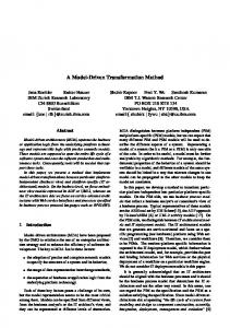
calculated installment is lower than half of the HB’s monthly income; if it is, the loan is accepted otherwise is rejected. In the end, the clerk creates the answer that has to be delivered to the home buyer and to be archived on a repository. The answer contains the retrieved/calculated information and the loan granting evaluation. A service system has to be developed to automate the above business process now performed by a human (the clerk). The clerk uses an external (credit bureau) system by mean of a GUI, however such system offers the same capability in a machine-processable version (i.e., a Web service), so the system under development can make use of it. A. Business Process Modelling The first phase of our method consists in describing the business process “as it is” by means of a UML model called BusinessProcessMod that represents the business before the introduction of the SOAsystem. At this level the UML model has to be close as much as possible to the given description of the business. The result of this activity in the Loan case study is the UML model reported in Fig. 1. As required, the model is composed by two diagrams: an activity diagram and a class diagram. In the Loan process, as reported in the note in the activity diagram, there are two business workers (home buyer and clerk), a system (credit bureau) and four business objects (form, info, installment, and answer). The variables (e.g., the decision DEC) are just containers for data values. Note that some operations on the business objects are given in passive form (e.g., ANS.archived() and ANS.sent(HB)) to abstract in the model from who will perform such actions. For example, we know that the clerk creates the answer, but nothing is said about who actually sends the answer to the HB. If, instead, it is assumed that the clerk will send the answer we could modify accordingly the model adding a sending operation to the Clerk class. This model, as all the other models created following our method at each phase, can be enriched, if it is necessary, with other UML diagrams or details that increase the level of information provided (e.g., pre-post conditions, invariant constraints and sequence diagrams). B. Placement The aim of the placement phase is deciding which part of the business process will be performed by the SOAsystem. The placement is done using a swimlane labelled by the name of the system (in our case study LoanSys). The part of the process that has to be performed by the SOAsystem will be placed inside the swimlane. It could happen that an activity is not totally of competence of the SOAsystem: in this case the activity will be placed over the lane boundary. The placement is correct only if:
(a) Activity Diagram
(b) Class Diagram Figure 1. •
•
•
Loan Case Study: BusinessProcessMod
at least one activity is placed inside the SOAsystem swimlane (no activities in the swimlane means that the system will do nothing); no activities performed by business workers are inside the swimlane (the system cannot replace the behaviour of a human being that it is unpredictable and not computable, e.g., an examiner of future employees or of the artistic value of a novel); at least an activity should be placed on the border of the swimlane (such an activity will result in communication between the system and some external entity);
•
no activity flow (control and object) can cross the swimlane boundary (a crossing flow means a hidden communication between the system and some external entity).
Therefore, only the following types of activities can be placed inside the SOAsystem swimlane: •
•
passive activity of a business object: it means that the SOAsystem will execute the activity on the object (e.g., ANS.archived()); activity performed by a pre-existing system: the SOAsystem will replace the existent system in the
Figure 2.
•
Loan Case Study: PlacementMod (first version – it does not satisfy the placement rules)
execution of the activity (not applicable to our case study); operations on the process variables (e.g., DEC = rejected).
The method prescribes first to do the placement following the requirements of the stakeholders, then to check if it is correct. In case of negative answer, the business process has to be refactored so that the placement will become correct. For example, activities previously performed by human being must be assigned to systems or to business objects, making them computable (e.g., the evaluation of an employee is made by marking a multiple choice questionnaire, or the quality of a novel is assured by a list of computable syntactic checks). If is not possible to refactor the model to satisfy the constraints, then the developer has to either change the placement or to conclude that the intended system is not doable. The result of this phase is the PlacementMod , having the form of a BusinessProcessMod where part of the activity diagram is included in one swimlane named as the system to develop. The creation of the PlacementMod for our system has required a model refactoring step in order to eliminate the
activities of the clerk. The initial placement (that does not satisfy the placement rules) is shown in Fig. 2, whereas in Fig. 3 we present the final placement obtained by one refactoring step, that transforms the activities of the clerk into operations over the business objects ANS and INST and over an external system CRBU. The idea is that now the three tasks are executed by LoanSys instead of by the clerk. C. High Level Design The goal of this phase is providing a high level design of the SOAsystem to build, providing a description of the activities carried out by the system itself. It is important to highlight that in this phase there are no details about the inner structure of the SOAsystem (e.g., information about the used services). During this phase a UML model called DesignMod is produced. We start from the PlacementMod and transform it. First, for each participant of type �businessWorker� and �system� we add to the activity diagram a new swimlane labelled by its name. Then, each action node on the border of the SOAsystem swimlane must be decomposed into several action nodes, including some call action nodes and accept nodes, deployed in the swimlanes of who calls and of who
(a) Activity Diagram
(b) Class Diagram Figure 3.
Loan Case Study: PlacementMod (Refactored – it satisfies the placement rules)
accepts/receives. In this model we represent the call and the 3 accept/receive actions respectively by and by . Then we add a dashed connector between the pairs of action nodes modelling communications of the system with the external entities. For example, the action FORM = HB.deliver(CLERK) present in the PlacementMod (Fig. 2) will become in the DesignMod (Fig. 4) a call action of the HB and an accept action of the LoanSys. Similarly, it happens for the actions INFO = CRBU.askedInfo(FORM) and ANS.sent(HB). 3 We are aware that the UML reference [14] asserts that only send signal actions can be represented in this way, but here we use this icon also for call actions.
In Fig. 4 we report the DesignMod for the Loan case study. The activity diagram contains three swimlanes: one is for LoanSys (the system under development), one for the business worker that interact with it (HB, the home buyer) and one for the external system (CRBU, Credit Bureau). Notice that at this level of description, all the activities in a swimlane are assumed as executed by the entity labelling the swimlane itself, and for simplifying the model we do no report such name in the various nodes; thus archive(FORM) is a shortcut for LoanSys.archive(FORM).
(a) Activity Diagram
(b) Class Diagram Figure 4.
Loan Case Study: DesignMod
D. Detailed Design The last phase produces a UML model called DetailedDesign that depicts the detailed design of the SOAsystem, composed by an orchestrator, some GUI(s) allowing the interaction with human users and external systems, and some services.
The orchestrator coordinates the execution of the different services and, if necessary, performs some data elaborations. Our method leads to the generation of an orchestrator following the model driven paradigm and the realization of the services following a “meet-in-the-middle” approach [6], namely building them from scratch or taking advantage of al-
Figure 5.
Loan Case Study: DetailedDesign, Orchestrator Behaviour
Figure 7.
Figure 6.
Loan Case Study: DetailedDesign, Architecture
Loan Case Study: DetailedDesign, Class Diagram
ready available services (e.g., offering technical and support functionalities) or assets wrapped to create services (such as, e.g., software components and legacy systems) [21]. It could happen that for using an existing service some minor modifications have to be done to the DetailedDesign (e.g., writing some adapters [12]). For the Loan case we have the following portfolio of already available services:
CreditService (for accessing CreditBureau), ArchiveService (for accessing the bank archive) and MailService (email).
The services are modelled by interfaces stereotyped by �service�, whose operations will model the ways for
interacting with the service itself. As in the other phases, the functionalities of a service (and needed data structures) may be modelled using the UML at different level of abstraction, e.g., adding more information about the behaviour
of their operation by means of pre-post conditions, invariant constraints and sequence diagrams. The orchestrator will be modelled by an activity diagram derived from the DesignMod in the following way. For each action node in the system lane of the activity diagram part of the DesignMod check whether it may be realized using a functionality of an available service. In case of a positive answer, the action is transformed in a call of the corresponding service functionality, otherwise ask if a new service may be developed to support it and then uses its functionalities to realize the action. If no service (existing or built on the moment) is available the effect of the action node will be realized by the orchestrator using the classical O-O statements (e.g., assignments or operation calls). In the Loan we built a new service, InstallmentService, for the computation of the installment for a loan (since it may be used by other banking activities, as personal loans and company financing). The DetailedDesign consists of: • a class diagram, describing the services, the GUI(s), and the datatypes used to model the needed data structures; • a representation of the system architecture by means of an object diagram; • an activity diagram modelling the behaviour of the orchestrator. In the following we show the DetailedDesign of the LoanSys. Fig. 6 reports the architecture for LoanSys; it is composed by the orchestrator, developed following our method, four services (ArchiveService, MailService, InstallmentService and CreditService), and a GUI (developed using standard techniques) that allows the HomeBuyer (1) to fill the Form and (2) to send the filled Form to the system (or more precisely to the Orchestrator) The Orchestrator (see Fig. 5) uses various global variables, e.g., ANS and DEC, and we assume that it can receive events (as for the FORM = receiveForm()) and call services (e.g., AS.save(FORM)). The used services and (global) variables are listed in a note placed under the activity diagram. Fig. 7 presents the class diagram. The ArchiveService has two operations corresponding to the offered capabilities to archive a form and an answer, whereas the CreditService has one operation with return type, modelling the capabilities to return the credit information concerning a form. III. I NDUSTRIAL P ROJECT The method proposed in this paper can be easily adapted to the development of domain specific systems. Indeed, in a project with two local companies, starting from this proposal, we have devised a method for developing VECMbased systems [9] and, as an application, used it to build a system, named V-protocol, for the management of the announcements of public competitions received by a company.
VECM is a software interface that allows developing systems not tied to specific characteristics of a particular ECM. An ECM (Enterprise Content Management) is a system used to capture, manage, store, and deliver enterprise content. It provides operations on documents such as: createDocument() and deleteDocument(). There are many ECM systems available on the market, e.g., Alfresco (open source) and SharePoint (Microsoft). Usually, the companies build their systems using several ECM systems characterized by different interfaces; for example, a bank that uses an ECM system to manage credit transfer and another one for loans. Often, the consequence of this practice is the development of a system highly coupled with the underlying ECM systems. The VECM software interface solves this problem. In practice, the VECM allows to develop systems not tied to the specific characteristics of a particular ECM. The adaptation of the method proposed in this paper to the VECM case consists of a modification of the fourth phase of our method (Sect. II-D). In this case there is a unique kind of service whose functionalities correspond to the VECM operations (e.g., createDocument() and deleteDocument()). All the operations not supported by VECM have to be executed by the orchestrator and if it is not possible they have to be substituted by calls to additional services. In this project, we experienced that our method leads to a proper use of the VECM component and allows creating VECMbased systems easily and effectively. IV. D ISCUSSION Our method leads the business modellers and developers in all the development phases: reducing errors (1) in the models and (2) in the final system, (3) being lightweight, (4) not exposing the company to vendor lock-in, with no need of (5) complex tools and (6) expensive training, and (7) allowing “high reuse” of personnel knowledge (in particular UML). Taking inspiration by [11] we summarize our experience with the proposed method by answering the following questions. What are the advantages / characteristics of the method? • It follows the model driven paradigm [8] and uses only a well-known subset of UML (substantially only class and activity diagrams). Thus, this justifies (6) and (7). • Our method is lightweight since it does not need expensive and complex software tools; it can be executed manually using only a UML modeller (e.g., Visual paradigm or Magic Draw). Thus, this justifies (3), (4) and (5). • All produced UML models (from the more abstract to the more concrete) are expressed using the “precise style” [4] to avoid the more common modelling errors [17] and to allow the final semi-automatic transformation. Thus, this justifies (1) and (2). From previous empirical studies, we have seen that the “precise style” is better than a lighter stile where nodes and arcs of
•
•
the activity diagrams are simply decorated by natural language text [4]. Differently from [11], where four different notations are used, our method concerns transformations between models expressed within the same language (UML “precise style”), and thus a unique notation is required in all phases and for all the aspects of the system to develop. Thus, this justifies (6) and (7). Our method leads the developers during the transformations prompting the needed decisions till to reach a detailed model that can be automatically transformed into running code. Thus, this justifies (1) and (2).
What can be done for improving the method? •
•
•
Currently, it only allows to describe the Web services interfaces. We plan to extend our method to provide a mechanism for the description of the Web services semantics [3] and realizations, making it possible to automatically generate their implementations following the model driven paradigm. Our method, up to now, makes use of class and activity diagrams only. We plan to extend our method to include other UML diagrams such as state machines and sequence diagram to provide more information on the system. It is not clear how much is the real manual effort of application of our method. In [9], it was acceptable but further experimentation is needed. V. R ELATED W ORK
Different approaches can be used in the development of SOA-based systems. They can be classified in three main categories: top-down (when at the beginning no services are available), bottom-up [7] (when as first step the services are collected/built) and meet-in-the-middle [6] (that combines the previous two approaches: some services are available at the beginning and others are developed). The latter two kinds of approaches are the most suited to migrate existing applications towards SOA. The top-down approach can be further divided into two types such as: business process driven and use case driven. Our approach belongs to the business process driven type meet-in-the-middle category. In literature, there are several works concerning the creation of SOA systems starting from UML [14] or BPMN [13] models. Usually, such models are automatically/semi-automatically or manually transformed in executable code. For example, Ouyang et al. [15] present a technique for generating BPEL code from business process models expressed in a core subset of BPMN and UML Activity Diagram. In practice, they only focus on the last transformation step of our method. Bauler at al. [2] propose how Model Driven Engineering and Business Process Management can be combined to generate executable BPEL
processes. Matjaz et al.4 show how, given a business model expressed in BPMN, is possible translate it into BPEL and execute the code on a SOA platform. Differently from them, we mainly focus on how to build the models. Transformations between models of different kind have been proposed too: for example Rychly et al., in [19], propose a method aimed to transform business processes modelled in BPMN into UML service diagrams. This is different from our method where the transformations involve models expressed with the same notation but at different levels of abstraction. We have chosen to use UML as the basic notation for our method but we are aware that others proposals are based on BPMN. We prefer to stick to use the UML only to require the method’s user to know and master a unique notation instead of two or more. The UML activity diagram has been shown as expressive as the BPMN 1.x diagrams [16]. Moreover, we believe that the BPMN 2.0 does not offer anything not already available in the very large list of constructs of UML (also if more a comprehensive analysis is needed): • BPMN private and public processes correspond to UML activity diagrams (more precisely the nonexecutable ones to the “ultra-light” activity diagrams of [18] and the executable ones to the “precise” activity diagrams); • BPMN 2.0 collaborations and choreography may be replaced by the UML collaborations and various kinds of interaction diagrams (e.g., sequence diagrams); • BPMN 2.0 conversations may be replaced by UML composite structure diagrams built with collaboration uses. On the converse BPMN 2.0 does not offer native means to describe the computational aspects of the processes (e.g., data structures and computations over them). VI. C ONCLUSION AND F UTURE W ORK In this paper we have proposed a model driven approach to develop SOA-based systems, starting from a business process model. Our approach is based on UML model transformations and starts from a model describing the business process “as it is”. The final artefact is a detailed design model of the SOAsystem, where the orchestrator component may be automatically transformed into running code (e.g., BPEL). The method can be considered effective and applicable in real systems because we have experienced [9] that usually business models are small so they can be manually built. Moreover, as general rule, having large business process models it is not advisable [20]. Future work will be devoted to refine our method and test it with other case studies. We intend apply it to a complex 4 http://www.oracle.com/technetwork/articles/soa/process-driven-soa100743.html
postal process already implemented in a legacy system that we have analyzed in a previous industrial project [10]. Moreover, we plan to design an Eclipse plug-in supporting our model driven method. We believe that Eclipse could be a good choice as development toolkit because of its popularity and Acceleo5 for the model to text transformations needed in the last step of our method. Furthermore, the Eclipse Plug-in Development Environment (PDE) provides a nice environment for creating plug-ins and integrating them with the Eclipse Platform. The support will offer the way to automatically checking the models to see if they meet all the constraints required by the method (e.g., in Sect. II-B) and a generator of BPEL code starting from the DetailedDesign produced in the last phase of the method. The BPEL code will invoke the existing Web services or the ones that have to be realized. All the detail contained in the DetailedDesign will allow an automatic translation of the orchestrator in BPEL. R EFERENCES [1] E. Astesiano and G. Reggio. Tight Structuring for Precise UML-based Requirement Specifications. In M. Wirsing, A. Knapp, and S. Balsamo, editors, Radical Innovations of Software and Systems Engineering in the Future, Proceedings 9th Monterey Software Engineering Workshop, Venice, Italy, Sep. 2002., number 2941 in LNCS. Springer Verlag, Berlin, 2004. [2] P. Bauler, F. Feltz, E. Frogneux, B. Renwart, and C. Thomase. Usage of model driven engineering in the context of business process management. In Proceedings of Multikonferenz Wirtschaftsinformatik, MKWI 2008, M¨unchen, 26-28.2.2008,. GITO-Verlag, Berlin, 2008. [3] C. Choppy and G. Reggio. A well-founded approach to service modelling with casl4soa: part 1 (service in isolation). In Proceedings of the 2010 ACM Symposium on Applied Computing, SAC ’10, pages 2451–2458, New York, NY, USA, 2010. ACM. [4] F. Di Cerbo, G. Dodero, G. Reggio, F. Ricca, and G. Scanniello. Precise vs. Ultra-Light Activity Diagrams - An Experimental Assessment in the Context of Business Process Modelling. In D. Caivano, M. Oivo, M. Baldassarre, and G. Visaggio, editors, Proceedings of 12th International Conference on Product-Focused Software Process Improvement (PROFES 2011), volume 6759 of Lecture Notes in Computer Science, pages 291–305. Springer Berlin / Heidelberg, 2011. [5] S. Dustdar, C. Dorn, F. Li, L. Baresi, G. Cabri, C. Pautasso, and F. Zambonelli. A Roadmap Towards Sustainable Selfaware Service Systems. In Proceedings of SEAMS 2010, pages 10–19, New York, NY, USA, 2010. ACM. [6] S. Inaganti and G. K. Behara. Service Identification: BPM and SOA Handshake. BPTrends, 2007. [7] S. Jones. Enterprise SOA Adoption Strategies: Using SOA to deliver IT to the Business. C4Media Publisher, 2006. [8] A. G. Kleppe, J. Warmer, and et al. MDA Explained: The Model Driven Architecture: Practice and Promise. AddisonWesley Longman Publishing Co., Inc, 2003. 5 http://www.acceleo.org/
[9] M. Leotta, G. Reggio, F. Ricca, and E. Astesiano. Building VECM-based Systems with a Model Driven Approach: an Experience Report. In Proceedings of 1st International Workshop on Experiences and Empirical Studies in Software Modeling (EESSMod 2011 co-located with MoDELS 2011), volume 785, pages 38–47. CEUR Workshop Proceedings, 2011. [10] M. Leotta, F. Ricca, G. Reggio, and E. Astesiano. Comparing the Maintainability of two Alternative Architectures of a Postal System: SOA vs. non-SOA. In Proceedings of 15th European Conference on Software Maintenance and Reengineering (CSMR 2011), pages 317–320. IEEE Computer Society Press, 2011. [11] A. Marchetto, C. D. Nguyen, C. Di Francescomarino, N. A. Qureshi, A. Perini, and P. Tonella. A Design Methodology for Real Services. In Proceedings of the 2nd International Workshop on Principles of Engineering Service-Oriented Systems (PESOS 2010), pages 15–21, New York, NY, USA, 2010. ACM. [12] R. C. Martin. Design principles and design patterns. 2000. [13] OMG. Business Process Model and Notation, v. 2.0. Standard, 2011. [14] OMG. Unified Modeling Language, Superstructure, v. 2.4. Specifications, 2011. [15] C. Ouyang, M. Dumas, S. Breutel, and A. ter Hofstede. Translating Standard Process Models to BPEL. In E. Dubois and K. Pohl, editors, Proceedings of 18th International Conference on Advanced Information Systems Engineering (CAiSE 2006), volume 4001 of Lecture Notes in Computer Science, pages 417–432. Springer Berlin / Heidelberg, 2006. [16] D. Peixoto, V. Batista, A. Atayde, E. Borges, R. Resende, and C. P´adua. A Comparison of BPMN and UML 2.0 Activity Diagrams. In VII Simposio Brasileiro de Qualidade de Software. Florianopolis, 2008. [17] G. Reggio, M. Leotta, and F. Ricca. “Precise is better than Light” A Document Analysis Study about Quality of Business Process Models. In Proceedings of 1st International Workshop on Empirical Requirements Engineering (EmpiRE 2011 co-located with RE 2011), pages 61–68. IEEE Digital Library, 2011. [18] G. Reggio, M. Leotta, F. Ricca, and E. Astesiano. Choosing the right style for modelling the business process with the UML: Complete version. Technical Report DISI-TR-12-02, DISI - University of Genova, Italy, April 2012. [19] M. Rychly and P. Weiss. Modeling of service oriented architecture: From business process to service realisation. In Proceedings of 3rd International Working Conference on Evaluation of Novel Approaches to Software Engineering (ENASE 2008), pages 140–146. Institute for Systems and Technologies of Information, Control and Communication, 2008. [20] L. S´anchez-Gonz´alez, F. Ruiz, F. Garc´ıa, and J. Cardoso. Towards Thresholds of Control Flow Complexity Measures for BPMN Models. In Proceedings of SAC 2011, pages 1445– 1450, New York, NY, USA. ACM. [21] H. M. Sneed. Migrating to Web services: A research framework. In Proceedings of Workshop on Service-Oriented Architecture Maintenance (SOAM 2007 co-located with CSMR 2007), 2007.