group of UML/fUML state/activity diagrams have been developed and the con- .... The ETL script consists mainly of group of transformation rules, part of them.
Towards a Practical Approach to Check UML/fUML Models Consistency Using CSP Islam Abdelhalim, Steve Schneider and Helen Treharne Department of Computing, University of Surrey
i.abdelhalim, s.schneider, h.treharne @ surrey.ac.uk
Abstract. This work provides an underpinning for a systems modelling approach based on UML and fUML together. It uses UML state diagrams as a starting point for modelling system object behaviours abstractly, then refining each state diagram by adding the implementation decisions in a form of a fUML activity diagram. Maintaining behavioural consistency between each UML state diagram and its corresponding fUML activity diagram is an important but difficult task. In this paper we introduce a framework that automates checking such consistency in a practical way. The framework is based on formalizing these diagrams into the process algebra CSP to do trace refinement checking using FDR2. One of the main contributions in this work is that we transform FDR2 output (counterexample in case of inconsistency) back to the UML/fUML model in a way that allows the modeller to debug the consistency problem. To be able to provide this kind of interactive feedback, the generated CSP model is augmented with traceability information. A case tool plugin based on the Epsilon model management framework has been developed to support our approach.
1
Introduction
The fUML (Foundational subset for Executable UML) standard [1] has been developed by OMG (Object Management Group) to allow for the execution of models. This implies having more complete and precise models which in many cases lead to complicated models that include implementation decisions. However, complicated models are hard to read, browse, understand and maintain. Moreover, checking consistency between such models and their specifications (modelled as abstract models) is a very difficult task. In contrast, abstract models are not complicated, but they cannot be used for model execution. To get the benefits of both (abstract and concrete models), the modeller starts with an abstract model and then refines it by adding more implementation detail until reaching a concrete one. This concept in the UML/fUML domain can be
applied by initially modelling a system using UML in an abstract way and then refining the model to reach a concrete fUML model. In the formal methods domain it is a common task to check consistency between abstract and concrete models using model checkers or theorem provers. However, this is not the case in the UML/fUML domain. Case tools that are used to draw the diagrams are concerned mainly with syntactical checking (i.e., checks if the UML/fUML diagram meets the UML/fUML standard specification). To import refinement into the UML/fUML domain, we are proposing a framework that allows checking UML/fUML model consistency. This framework is based on formalizing UML/fUML models into the CSP (Communicating Sequential Processes) [2] formal language, then perform a formal model checking using FDR2 (the Failures-Divergences Refinement tool) [3]. If FDR2 detects an inconsistency it will generate a counter-example which shows a trace that led to this inconsistency. To completely isolate the modeller from dealing with the formal methods domain, our framework reflects this counter-example back to the UML/fUML model (through a model debugger). Although checking consistency between semi-formal models (e.g., UML) has been addressed many times in the literature [4, 5] using formal methods, to our knowledge, this paper is the first attempt to check consistency between non-executable and executable semi-formal models. Also the provision of a modeller friendly consistency checking feedback out of the formal one is one of the main contributions in this paper. We differentiate between two types of model inconsistency. First, inter-model inconsistency, which occurs if two (or more) diagrams with different types are not consistent (e.g., a state diagram and a related sequence diagram in the same UML model). Second, intra-model inconsistency, which occurs if two (or more) diagrams with the same type are not consistent (e.g., a version of a state diagram and a refined version represented as a state diagram as well). Our work is a combination of these two kinds of inconsistency because we start by modelling the object behaviour as an UML state diagram and refine it to a fUML activity diagram that represents the same object behaviour augmented with more implementation detail. Hence, we will refer to this as behavioral consistency. The formalization is done automatically by transforming UML/fUML diagrams into CSP processes. We made use of Epsilon [6] as one of the available MDE (Model Drive Engineering) frameworks to support the transformation based on available UML2 [7], fUML [1] and CSP [8] meta-models. Epsilon is one of several components that build up our framework which has been implemented as a MagicDraw 1 [9] plugin to allow modellers to seamlessly use our approach during the system modelling process. The approach has been tested using the Tokeneer ID Station [10] case study. A group of UML/fUML state/activity diagrams have been developed and the con1
MagicDraw is an (award-winning) architecture, software and system modeling case tool. It also supports additional plugins to increase its functionalities
sistency between them has been verified using our approach. Due to limitations space we will include a simple example (Microwave Oven from [11]) to illustrate the main concepts through the paper. We assume the reader of this paper has an understanding of the UML2 standard, CSP and FDR2. The rest of this paper is organised as follows. In Section 2, we give a background to the fUML standard and the CSP syntax used in this paper. In Section 3, we give an overview of our approach and its main components. In Section 4, we describe the Model Formalizer component and how it works. In Section 5, we describe how consistency is checked between particular UML and fUML diagrams. In Section 6, we describe how we provide the modeller with helpful feedback through a Formalization Report and the Model Debugger. In Section 7, we outline the implementation of the approach. Finally, we discuss related work and conclude in Sections 8 and 9 respectively.
2 2.1
Background fUML
As defined by OMG, fUML is a standard that acts as an intermediary between “surface subsets” of UML models and platform executable languages. The fUML subset has been defined to allow the building of executable models. Codegenerators can then be used to automatically generate executable code (e.g., Java) from the models. Another option is to use model-interpreters that rely on a virtual machine to directly read and run the model (e.g., fUML Reference Implementation [12]). The fUML standard includes class and activity diagrams to describe a system’s structure and behaviour respectively. Some modifications have been applied to the original class and activity diagrams in the UML2 specification [13] to meet the computational completeness of fUML. The modifications have been done by merging/excluding some packages in UML2, as well as adding new constraints, such as: – Variables are excluded from fUML because the passing of data between actions can be achieved using object flows. – Opaque actions are excluded from fUML since, being opaque, they cannot be executed. – Value pins are excluded from fUML because they are redundant due to the use of value specifications to specify values. The operational semantics of fUML is an executable model with methods written in Java, with a mapping to UML activity diagrams. The declarative semantics
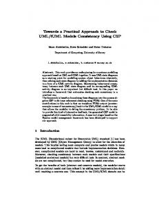
of fUML is specified in first order logic and based on PSL (Process Specification Language) [14]. UML/fUML example Throughout this paper we use a simple example of a microwave oven that consists of two classes: Controller and Heater. Figure 1 shows the state machine (Controller SD) that represents the Controller active object behaviour. The object can be in one of three different states (DoorOpen, ReadyToCook and Cooking) based on the incoming events (doorClosed, buttonPressed, ...). For example, if the object was in the ReadyToCook state and the buttonPressed event happened, it will enter the Cooking state.
Controller_SD doorClosed
ReadyToCook
DoorOpen
buttonPressed
Cooking
doorOpened
timerTimesout doorOpened
Fig. 1: UML State Diagram of the Microwave Controller
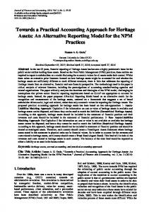
As a result of refining the Controller state digram by adding some implementation detail, we obtain the Controller fUML activity diagram depicted in Figure 2. The added implementation detail include: – Setting the value of the class attributes (e.g., setting isCooking attribute to FALSE using the valueSpecification and addStructuralFeatureValue actions). – Sending signals (equivalent to the state diagram events) to objects (e.g., sending stopHeaterSignal to the Heater object). – Representing the object internal decisions (e.g., timer expiration). Although we do not include all the implementation details for this object it is obvious that the executable model is more complicated. Our experience with modeling large systems showed that checking consistency between those two kinds of models (abstract and concrete) manually is a challenging task.
2.2
CSP
CSP is a modelling language that allows the description of systems of interacting processes using a few language primitives. Processes execute and interact by means of performing events drawn from a universal set Σ. Some events are of
activity Controller_AD ( selfObj : Controller, heaterObj : Heater )
Value(FALSE)
selfObj : Controller
isCooking Accept (doorOpened, buttonPressed) doorOpenedSignal
heaterObj : Heater
buttonPressedSignal Send (startHeater)
Send (stopHeater)
Accept (doorClosed)
value(TRUE)
selfObj : Controller
isCooking timerExpired
timerNotExpired
Send (timerTimesout)
Accept (timerTimesOut, doorOpened)
doorOpenedSignal
timerTimesoutSignal
Fig. 2: fUML Activity Diagram of the Microwave Controller
the form c.v , where c represents a channel and v represents a value being passed along that channel. Our UML/fUML formalization considers the following subset of the CSP syntax:
P ::= a → P | c?x → P (x ) | d !v → P | P1 2 P2 | P1 u P2 | P1 k P2 | P \ A A B
| let N1 = P1 , . . . , Nn = Pn within Ni The CSP process a → P initially allows event a to occur and then behave subsequently as P . The input process c?x → P (x ) will accept a value x along channel c and then behave subsequently as P (x ). The output process c!v → P will output v along channel c and then behave as P . Channels can have any number of message fields, combination of input and output values. The choice P1 2 P2 offers an external choice between processes P1 and P2 whereby the choice is made by the environment. Conversely, P1 u P2 offers an internal choice between the two processes.
k
The parallel combination P1
P2 executes P1 and P2 in parallel. P1 can
A B
perform only events in the set A, P2 can perform only events in the set B , and they must simultaneously engage in events in the intersection of A and B . The hiding operation P \ A describes the case where all participants of all events in the set A are described in P . All these events are removed from the interface of the process, since no other processes are required to engage in them. The let . . . within statement defines P with local definitions Ni = Pi . Traces model Processes in CSP interact with their environment (another process, user, or combination of both) through events in their interface. A process P is refined by a process Q if the set containing all the possible traces that can be generated from process Q is a subset (or equals) of those traces of P . This definition can be expressed as: P vT Q.
3
Approach overview
To automate the formalization and the feedback process, we have designed a framework that facilitates this functionality and at the same time isolates the modeller completely from the formal methods domain (CSP). Figure 3 shows the architecture of this framework and the modeller interaction points.
UML Meta-model Formalization Report
fUML Meta-model
CSP Meta-model
UML State Diagram
Modeller
fUML Activity Diagram
Model Formalizer
CSP-to-UML/fUML Mapping Table Model Debugger
CSP Script
FDR2
Counter Example
Fig. 3: Approach Architecture
Initially the modeller uses a case tool (e.g., MagicDraw) to draw the UML state diagrams and the corresponding fUML activity diagram for each active class in the system. To check consistency between the UML/fUML diagrams, the modeller should initiate the checking process. As a first step the diagrams will
be converted to the XMI (XML Metadata Interchange) [15] format, thus it can be read by any MDE framework. The Model Formalizer then processes the input diagrams and transforms them to a CSP script based on a group of transformation rules and the input UML2 [7], fUML [1] and CSP [8] existing meta-models. In case there is a problem in the formalization process, the Model Formalizer generates a Formalization Report with the error cause(s). The Model Formalizer also generates a CSP-toUML/fUML mapping table which maps each CSP event ID to its corresponding ID for the UML/fUML element. The generated CSP script subsequently used as an input to FDR2 that performs the consistency automatic checking. If there is a consistency problem FDR2 generates a counter-example which includes the traces (sequence of events) that led to the problem. In case of inconsistency, the Model Debugger can be used by the modeller to trace the consistency problem source. In order to do that, the Model Debugger reads the counter-example and makes use of the CSP-to-UML/fUML mapping table to reflect the traces on the displayed diagrams in the case tool. The modeller can deal with the Model Debugger using GUI (Graphical User Interface) controls (step forward, step backward, breakpoints, etc.). Having consistent UML/fUML diagrams will make the code generation (or model interpretation) a safer and direct process, because the modeller will be confident that the generated code from the fUML model is compatible with the system UML model.
4
The Model Formalizer
The Model Formalizer mainly transforms a source model (UML/fUML diagrams) into a formal representation (CSP script). We used Epsilon as a MDE framework to handle the transformation in two stages; Firstly, a Model-to-Model transformation from the UML/fUML model to CSP model using ETL (Epsilon Transformation Language) [16] and secondly a Model-to-Text transformation from the generated CSP model to a CSP script using EGL (Epsilon Generation Language) [16]. Epsilon also requires the source/target models’ meta-models, so we used the available UML2 meta-model [7] as well as the CSP meta-model used in our previous work [8]. The ETL script consists mainly of group of transformation rules, part of them related to the UML state diagram elements (4 rules) and the others related to the fUML activity diagram elements (11 rules). Figure 4 shows a simple rule (to clarify the concept) which is used to transform a state machine (e.g., Controller SD) to a CSP localized process (e.g., Controller SD Proc). The figure includes the ETL rule which can be understood by referring to the included UML and CSP meta-models segments.
Rule(1) StateMachine_To_MainProcess Controller_SD
Corresponding Meta-model StateMachine
UML
CSP
Controller_SD_Proc = let .. .. Within STATE_1
ProcessExpression
ProcessID name: String
processExpression
processID
ProcessAssignment
ETL Rule
rule StateMachine_To_MainProcess transform sm : SD!StateMachine to pid : CSP!ProcessID, pa : CSP!ProcessAssignment { pa.processID := pid; pa.processExpression := localProc;
process LocalizedProcess
pid.name = sm.name + '_Proc'; }
Fig. 4: Rule(1) for Transforming State Machines to CSP Localized Processes
The models elements can be accessed using the variables SD and CSP with the ‘!’ operator. The localProc variable represents the main LocalizedProcess that all other sub-processes belongs to it. By executing this rule two CSP elements will be created (instances from: ProcessID and ProcessAssignment) and added to the CSP model. The reader can refer to [16] for more detail about the Epsilon languages and to a previous paper [17] for all the fUML activity diagram mapping rules. After applying the ETL rules to the UML state diagram shown in Figure 1 and then applying the EGL script to the result, the CSP process in Figure 5 will be generated. According to Rule(1) in Figure 4, the state machine has been translated into a localized CSP process. Each state is translated to a CSP subprocess (e.g., ReadyToCook state translated to the process STATE 2). The inState event is used to identify the current active state (ST 1, ST 2, etc.) which will be used for traceability. The accept event represents signals (e.g., doorClosed , buttonPressed , etc.) reception by the object to change its state. Applying the ETL rules followed by the EGL script on the fUML activity diagram, shown in Figure 2, will result in the CSP process shown in Figure 6. The main activity is translated to a localized CSP process, Controller AD Proc, where each node inside it is translated to a sub-process. The first three processes AC 1, AC 2 and AC 5 correspond to the first three actions of the Controller AD. AC 1 and AC 2 represent the Value Specification and Add Structural Feature Value actions respectively by setting var to FALSE and passing it AC 2 which sets the isCooking attribute (structural feature) to the passed value.
Controller SD Proc (selfObj ) = let STATE 1 = inState!ST 1 → accept!selfObj !doorClosed → STATE 2 STATE 2 = inState!ST 2 → ( accept!selfObj !doorOpened → STATE 1 2 accept!selfObj !buttonPressed → STATE 3) STATE 3 = inState!ST 3 → ( accept!selfObj !timerTimesout → STATE 2 2 accept!selfObj !doorOpened → STATE 1) within STATE 2
Fig. 5: The Corresponding CSP Process for the Microwave Controller UML State Diagram
Controller AD Proc (selfObj , heaterObj ) = let AC 1 = valueSpec!selfObj ?var : FALSE !NID1 → AC 2(var ) AC 2(var ) = addStructFtrVal !selfObj !isCooking!var !NID3 → AC 5 AC 5 = registerSignals!selfObj !rp1!NID5 → ( accept!selfObj !doorOpenedSignal → ... 2 accept!selfObj !buttonPressedSignal → AC 12) AC 12 = send !selfObj !heaterObj !startHeaterSignal !NID9 → ... .. . ND2 = timerNotExpired !selfObj → ... u timerExpired !selfObj → ... within AC 1
Fig. 6: Fragment of the Corresponding CSP Process for the Microwave Controller fUML Activity Diagram (up to decision node for timer expiry)
According to the fUML standard, the AcceptEvent action registers the expected signals to a list (called waiting event accepters) and then waits for the signals. This logic was implemented in AC 5 using the registerSignals event, then the accept event. Any decision node with a control flow incoming edge is translated
to a non-deterministic choice. Hence, process ND2 corresponds to the timer expiry decision node. Some of the events include an ID parameter (e.g., NID1), this ID will be used for traceability explained in Section 6. Unlike our previous work [17, 18], we do not consider inter-object communication between objects in this paper. However, our formalization includes all the needed information to conduct inter-object behaviours analysis in the future. This is the reason for formalizing elements that will not affect the behavioural consistency checking (e.g., formalizing the SendSignal action in AC 12). Nevertheless, our formalization does not cover all aspects and properties of the UML/fUML standards as we just focus on the elements included in the used case study (Tokeneer).
5
Behavioural consistency checking
Having the two kinds of diagrams (UML state diagram and fUML activity diagram) formalized into CSP makes the behavioural consistency checking using FDR2 a direct process. We use FDR2 to handle the model checking based on the traces refinement semantic model [2]. From one point of view of the process execution, one process is consistent with another if its behaviours are allowed by the other. Compared to other semantic models (e.g., stable failures), this one is sufficient to check if the two UML/fUML diagrams are behaviorally consistent. Initially, the generated CSP script was augmented (by the Model Formalizer) with the following assertion to let FDR2 check the refinement between the two CSP processes. c0 and h0 represent instances of the Controller and Heater classes respectively. The set hiddenEvents includes all the events except the accept event. Controller SD Proc (c0) vT Controller AD Proc (c0, h0) \ hiddenEvents
However, in the case of an inconsistency, the generated counter-example (a trace leading to this inconsistency) by FDR2 includes the sequence of events from the Controller AD Proc process. As will be described in Section 6, having the traces from one side is not enough for the Model Debugger to highlight the inconsistency problem on the corresponding UML/fUML diagrams. We also need to retrieve the states that the specification has passed through. To overcome this issue, we introduce an additional process Controller SD TR. The Controller SD TR process is a copy of the Controller AD Proc except that it stops when any accept event other than those allowed by the Controller AD Proc process happens. For example, the sub-process STATE 2 in Controller SD TR is generated as follow:
STATE 2 = inState!ST 2 → ( accept!selfObj !doorOpened → STATE 1 2 accept!selfObj !buttonPressed → STATE 3 2 accept!selfObj ?x → STOP )
The refinement check (assertion) we now perform is: Controller SD Proc (c0) vT (Controller AD Proc (c0, h0) k Controller SD TR (c0)) \ hiddenEvents {|accept|}
The parallel combination above represents a process that follows the states in the Controller SD Proc process, but without affecting the refinement checking. This representation of the refinement assertion has solved the pre-described issue of debugging, as now the generated counter-example by FDR2 includes the states of the two main processes (Controller SD Proc and Controller AD Proc) which are needed to construct the appropriate feedback to the modeller. To show the effect of this technique, in the Controller fUML activity diagram in Figure 2, assume that the modeller (by mistake) connected the edge coming out from the Accept(doorClosed ) action to the Send (stopHeater ) action instead of the Value(FALSE ) action. After the formalization and performing the refinement checking using FDR2, the generated counter-example is as follow:
The idea of using Controller SD TR derived from Controller SD Proc to track the states in the specifications, is one of this paper’s contributions. We could not have been able to see the inState event in the trace above without this.
6
Formalization and model checking feedback
The modeller will be provided with two kinds of feedback after the formalization process or behavioural consistency checking. The following sections describe them with respect to the framework components.
6.1
Formalization Report
The first kind of feedback represents the success or failure of the formalization process and it is presented to the user through a Formalization Report. In our approach, not all UML/fUML diagrams can be formalized. They have to fulfill minimum requirements in order to be formalized. These requirements include the existence of certain elements and the assignment of certain properties. For example, the Model Formalizer cannot formalize a UML state diagram that does not include a connected pseudo state, because this will prevent the Model Formalizer from setting the initial CSP sub-process in the within clause. Another example is not assigning the name of an edge emerging from a decision node in a fUML activity diagram. To be able to check the formalization ability of each diagram (“is formalizable?”), each transformation rule is divided into two parts. The first part checks for the required elements/assignments, and if met, the second part performs the transformation. Otherwise, a formalization error is reported to the modeller that guides him to the missing items. 6.2
Model Debugger
The second kind of feedback is provided in case of inconsistency and it represents the counter-example generated by FDR2. This feedback is provided to the modeller through the Model Debugger. As mentioned in Section 3 , the Model Debugger component allows the modeller to interactively debug the consistency problem visually on the displayed UML/fUML activity diagram using GUI controls. The controls allow the modeller to step forward/backward (i.e., move within the sequence of traces of the counter-example with one trace forward/backward). Whilst the modeller is navigating through the events of the counter-example, the corresponding UML/fUML elements of the events are highlighted on the displayed diagrams to help him locate the source of the inconsistency. Also he can put a breakpoint on one of the UML/fUML elements and execute all events until reaching this element. Figure 7 shows the GUI controllers (inside the Model Debugger toolbar) and how the UML/fUML elements are highlighted (surrounded by a coloured square) in the diagrams. The Model Debugger cannot work without the data that has been collected during the formalization and the model checking processes. As mentioned in Section 4, the Model Formalizer generates an ID for the CSP processes’ events. It also generates the CSP-to-UML/fUML mapping table which holds the CSP events IDs and their corresponding UML/fUML elements IDs (long alphanumeric references generated by MagicDraw). Table 1 shows a sample of this table which helps the Model Debugger to know which UML/fUML elements to highlight given the CSP event ID included in the counter-example. It is clear now why we formulated the assertion statement (in Section 5) to force FDR2 to include the state diagram CSP process (Controller SD TR) traces in the counter-example.
Table 1: Sample CSP-to-UML/fUML Mapping Table CSP Event ID ST2 NID3
UML/fUML Element ID 16 4 8a01c6 129197859 209692 741 16 4 80a01c6 128715854 342172 469
We consider providing the model checking results through a Model Debugger to be another contribution of our work.
7
Approach implementation
We have implemented our approach as a MagicDraw plugin called “Compass” (Checking Original Models means Perfectly Analyzed Systems). To use Compass, the modeller should first model the system objects’ behaviours using UML state diagrams, then refine each diagram (by adding more implementation details) by modelling the same behaviour using an fUML activity diagram. At this point, the modeller can use Compass to start the consistency checking between the two kinds of diagrams and get the feedback as described in Section 6. Figure 7 shows a screen shot of MagicDraw during debugging an inconsistency problem using the Model Debugger toolbar. The screen shows the Microwave controller UML state diagram and its corresponding fUML activity diagram with two highlighted elements (ReadyToCook state and isCooking action). There is also another window that shows the executed traces (states and actions). This is not included in the screen shot due to lack of space. We would argue that implementing the approach in a form of a plugin to an already existing case tool is more practical for several reasons. Compared to a standalone formalization application, a plugin will allow for having a single integrated modelling environment. Also modifying the plugin to work with other case tools is a straightforward task, which means that the plugin can be made available for several case tools. This in turn will allow the modeller who is already using a certain case tool not to change his modelling environment to check his models (or even re-check legacy models).
8
Related work
Much research work has been done on formalizing UML models to check different properties. For example, the authors in [19, 18, 17] used such formalizations to make sure that their UML models are deadlock free. Others, such as [20, 21], used the formalization to check certain safety properties in the input models. Inter-model consistency (i.e., are the diagrams of the same model consistent?) can be checked by formalization as well. Zhao et al. [22] followed that concept by
Model Debugger
Fig. 7: Screen shot of MagicDraw Running Compass
checking consistency between the UML state diagram and its related sequence diagrams using Promela as a formal language. Graw et al. [5] proposed intra-model consistency through checking refinement between abstract and more detailed UML state and sequence diagrams depending on cTLA (compositional Temporal Logic of Actions) as a formal representation. Ramos et al. [4] proposed formalizing UML-RT into Circus to prove that the model transformation preserved the original model semantics. Most of the reviewed work in this field performs the model transformation automatically (from UML to the formal language). Some of these work depended on MDE tools to do the transformation. Varr´o et al. in [23] summarized a comparison between eleven different MDE tools used to transform from UML activity diagrams into CSP (UML-to-CSP case study [24]), as part of the AGTIVE’07 tool contest. Also Treharne et al. [8] used the Epsilon framework to transform UML state diagrams to CSPkB. Providing modeller friendly feedback to report the model checking results has been addressed only a few times in the literature. The authors in [25, 26] proposed presenting the model checking results (e.g., counter-example) as an object diagram that represents a snapshot of the system during the error. Alternatively, the authors in [27, 28] proposed compiler style-errors with valuable feedback. None of the reviewed work has been concerned with checking consistency between non-executable and executable semi-formal models (e.g., UML and fUML). Sim-
ilarly, providing the formalization feedback interactively through a model debugger has not been developed.
9
Conclusion and future work
An approach to check behavioural consistency between UML state diagrams and their corresponding fUML activity diagrams has been presented in this paper. The approach depends on a framework that formalizes the UML/fUML diagrams automatically into CSP and then uses FDR2 to handle the model checking. In the case of inconsistency, the framework reflects FDR2 output (counter-example) to the original UML/fUML model through the Model Debugger. We have developed an implementation of this framework as a MagicDraw plugin called Compass. Compass made use of the Epsilon MDE framework to translate the UML/fUML diagrams into a CSP script in two stages (Model-to-Model then Model-to-Text). The practicality of this approach comes from several aspects. First, by its attempt to check consistency between non-executable and executable models, which we believe will be very important as fUML spreads within the normal software development process. Second, we believe that providing the model checking results through the Model Debugger is more helpful in identifying the source of the problem instead of just showing an object diagram to the modeller. Finally, by implementing the approach as a plugin to a case tool and depending on an MDE framework instead of writing our formalizer from scratch. Validating the approach’s functionality and applicability was achieved by applying it on a non-trivial case study (Tokeneer). Using MagicDraw and Compass during the system modelling helped to identify several inconsistencies between the UML abstract state diagrams and their corresponding fUML activity diagrams. As future work, we will consider inter-object interaction to provide a similar framework that checks deadlocks and other behavioural properties. We will also aim to provide additional feedback to the user as a UML sequence diagram which visualizes the counter-examples as object interactions.
References 1. OMG: Semantics of a foundational subset for executable UML models (fUML) Version 1.0, http://www.omg.org/spec/fuml/ (February 2011) 2. Schneider, S.: Concurrent and Real-Time Systems: the CSP Approach. Wiley (1999) 3. Formal Systems Oxford: FDR 2.91 manual (2010) 4. Ramos, R., Sampaio, A., Mota, A.: A semantics for UML-RT active classes via mapping into circus. In: FMOODS. (2005) 99–114
5. Graw, G., Herrmann, P.: Transformation and verification of Executable UML models. Electron. Notes Theor. Comput. Sci. 101 (2004) 3–24 6. Epsilon Project. http://www.eclipse.org/gmt/epsilon/ 7. UML2 Project. http://www.eclipse.org/modeling/mdt/?project=uml2 8. Treharne, H., Turner, E., Paige, R.F., Kolovos, D.S.: Automatic Generation of Integrated Formal Models Corresponding to UML System Models. In: TOOLS (47). (2009) 357–367 9. MagicDraw case tool. http://www.magicdraw.com/ 10. Barnes, J., Chapman, R., Johnson, R., Widmaier, J., Cooper, D., Everett, B.: Engineering the tokeneer enclave protection software. In: 1st IEEE International Symposium on Secure Software Engineering. (March 2006) 11. Mellor, S.J., Balcer, M.J.: Executable UML, A Foundation for Model-Driven Architecture. Addison-Wesley (2002) 12. OMG: fUML Reference Implementation. http://portal.modeldriven.org 13. OMG: Unified modeling language (UML) superstructure (version 2.3) (2010) 14. Gruninger, M., Menzel, C.: Process Specification Language: Principles and Applications. AI Magazine 24(3) (2003) 63–74 15. Metadata Interchange (XMI), X. http://www.omg.org/spec/XMI/ 16. Dimitrios kolovos, L.R., Paige, R.: The Epsilon Book 17. Abdelhalim, I., Sharp, J., Schneider, S., Treharne, H.: Formal Verification of Tokeneer Behaviours Modelled in fUML Using CSP. 6447 (2010) 371–387 18. Turner, E., Treharne, H., Schneider, S., Evans, N.: Automatic generation of CSPkB skeletons from xUML models. In: Proceedings of the 5th international colloquium on Theoretical Aspects of Computing, Berlin, Springer-Verlag (2008) 364–379 19. Ng, M.Y., Butler, M.: Towards formalizing UML state diagrams in CSP. In Cerone, A., Lindsay, P., eds.: 1st IEEE International Conference on Software Engineering and Formal Methods, IEEE Computer Society (2003) 138–147 20. Hansen, H.H., Ketema, J., Luttik, B., Mousavi, M., van de Pol, J.: Towards model checking Executable UML specifications in mCRL2. ISSE (2010) 83–90 21. Balser, M., Bumler, S., Reif, W., Thums, A.: Interactive verification of UML state machines. In: Formal Engineering Methods (ICFEM04), LNCS 3308, Springer (2004) 434–448 22. Zhao, X., Long, Q., Qiu, Z.: Model checking dynamic UML consistency. In: ICFEM. (2006) 440–459 23. Varr´ o, D., Asztalos, M., Bisztray, D., Boronat, A., Dang, D.H., Geiß, R., Greenyer, J., Van Gorp, P., Kniemeyer, O., Narayanan, A., Rencis, E., Weinell, E.: Transformation of UML Models to CSP: A Case Study for Graph Transformation Tools. (2008) 540–565 24. Bisztray, D., Ehrig, K., Heckel, R.: Case Study: UML to CSP Transformation. In Applications of Graph Transformation with Industrial Relevance. (2007) 25. Cabot, J., Claris´ o, R., Riera, D.: Verifying UML/OCL operation contracts. In: IFM ’09: Proceedings of the 7th International Conference on Integrated Formal Methods, Berlin, Heidelberg, Springer-Verlag (2009) 40–55 26. Shah, S.M.A., Anastasakis, K., Bordbar, B.: From UML to Alloy and back again. In: MoDeVVa ’09: Proceedings of the 6th International Workshop on Model-Driven Engineering, Verification and Validation, New York, NY, USA, ACM (2009) 1–10 27. Thierry-Mieg, Y., Hillah, L.M.: UML behavioral consistency checking using instantiable Petri nets. ISSE 4(3) (2008) 293–300 28. Planas, E., Cabot, J., G´ omez, C.: Verifying action semantics specifications in UML behavioral models. In: CAiSE ’09: Proceedings of the 21st International Conference on Advanced Information Systems Engineering, Berlin, Heidelberg, SpringerVerlag (2009) 125–140