Feb 22, 2007 - modules are often quite complex, and need extensive customisation to suit the number and type of subsyste
February 22, 2007
Towards a Practical Design Methodology with SystemVerilog Interfaces and Modports Jonathan Bromley Senior Consultant Doulos, Ringwood, UK
[email protected]
Notes This paper was presented at DVCon 2007 (see www.dvcon.org) where it was judged by delegates to be joint Best Paper. The full text of the paper is available in the DVCon Proceedings, and on the Doulos website www.doulos.com. The other joint winner was: FEV’s Greatest Bloopers: False Positives in Formal Equivalence
Erik Seligman, Joonyoung Kim Digital Enterprise Group, Intel Corporation, Hillsboro, OR
Reprint 27-Feb-2007
Copyright © 2007 DVCon and Doulos Ltd. All Rights Reserved
1
Towards a Practical Design Methodology with SystemVerilog Interfaces and Modports
DVCon 2007
Multi-level bus architecture Many of today's FPGA and ASIC designs use interconnect schemes such as AMBA (published by ARM Ltd) or other standards. Bus fabric
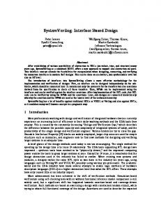
Unlike traditional rack-and-cards systems, an on-chip system is likely to use many different forms of interconnect – our example shows the high-performance AXI and AHB buses co-existing with the much simpler, lower-performance APB. Furthermore, point-to-point connection is usually preferable to shared (multidrop) interconnect. It is therefore usually necessary to have one or more bus switching and bridge blocks, shown here as a "Bus fabric" module. Such modules are often quite complex, and need extensive customisation to suit the number and type of subsystems in each individual application. The use of bus fabric modules typically leads to multiple instances of a given interconnect structure at the top level of the design. In our example we have two instances of the AXI bus, and two instances of APB.
2
Copyright © 2007 DVCon and Doulos Ltd. All Rights Reserved
Reprint 27-Feb-2007
Multi-level bus architecture Enclosing top-level module CPU
DMA
Memory AHB
AXI
AXI
Bus fabric
APB
Peripheral
APB
Peripheral
Peripheral
Peripheral
Notes
Reprint 27-Feb-2007
Copyright © 2007 DVCon and Doulos Ltd. All Rights Reserved
3
Towards a Practical Design Methodology with SystemVerilog Interfaces and Modports
DVCon 2007
The need for encapsulated interconnect Because there are two APB buses at the same level of hierarchy, we have a problem when we come to create the wiring. The standard name for the address bus in APB is PADDR, but we can't use that name for two separate signals! In a traditional system we would be obliged to invent two different names for the two PADDR signals – and, of course, do the same over and over again for all the other signals too. Perhaps you use scripts, or a graphical design entry tool, to do all this tiresome top-level wiring, in which case the signals will probably get unfathomable names such as PADDR_1 and PADDR_2. Alternatively you may do it manually, which is unpleasantly laborious and error-prone. Neither solution seems ideal. We could solve this problem elegantly if we had some way to encapsulate the whole of an APB (or any other) interconnect in a single structure. As we will see in the next few pages, SystemVerilog's interface construct provides just such an encapsulation.
4
Copyright © 2007 DVCon and Doulos Ltd. All Rights Reserved
Reprint 27-Feb-2007
The need for encapsulated interconnect Enclosing top-level module CPU
DMA
Memory AHB
AXI
AXI
Bus fabric Conflicting signal names PADDR PADDR
Peripheral
•
Peripheral
Peripheral
Peripheral
Multi-level bus structures may have many instances of the same set of bus signals with standard names
Notes
Reprint 27-Feb-2007
Copyright © 2007 DVCon and Doulos Ltd. All Rights Reserved
5
Towards a Practical Design Methodology with SystemVerilog Interfaces and Modports
DVCon 2007
Data structures are not enough First, though, we'll look at an alternative possibility. SystemVerilog also offers the struct feature, allowing users to define a data type that contains a collection of distinct data items. Our example shows the definition of a new data type APB that can be used as a "cookie cutter" to create new variables, each of which represents the complete set of signals needed for the APB interconnect. However, if you try to use this mechanism you will find exactly the same difficulties that VHDL users have suffered for many years when trying to use the RECORD construct to do such things: •
it is impossible to specify input or output directions individually for the various components of the record, which is very troublesome;
•
a module wishing to connect to such a structure must simply connect to all of it – there is no way to distinguish the various different roles, such as master or slave, that different modules may have;
•
signals whose scope extends outside the bus itself, such as clock and reset, cannot be conveniently integrated into this arrangement.
These are exactly the problems that SystemVerilog interfaces were designed to solve, as we'll see on the next page.
6
Copyright © 2007 DVCon and Doulos Ltd. All Rights Reserved
Reprint 27-Feb-2007
Data structures are not enough Enclosing top-level module
• • •
Memory
AXI
t_APB_d t_APB_d PRDATA; PRDATA; }} APB APB ;;
DMA
AXI
logic PWRITE; logic PWRITE; t_APB_a t_APB_a PADDR; PADDR; t_APB_d t_APB_d PWDATA PWDATA
CPU
AHB
typedef typedef struct struct {{ logic PSEL; logic PSEL; logic PENABLE; logic PENABLE;
Bus fabric
APB
Peripheral
APB
Peripheral
Peripheral
Peripheral
... ... APB APB apb_1, apb_1, apb_2; apb_2; ... ...
No direction information No distinction of roles (slave, master, ...) Hard to integrate global signals (clock, reset, ...)
Notes
Reprint 27-Feb-2007
Copyright © 2007 DVCon and Doulos Ltd. All Rights Reserved
7
Towards a Practical Design Methodology with SystemVerilog Interfaces and Modports
DVCon 2007
Interface captures interconnect Here we see the simplest way to use an interface to capture a structured set of interconnect. The interface is defined in much the same way as a module; indeed, the writer is strongly of the opinion that interfaces and modules are very nearly the same! Interface contents The interface contains declarations of nets or (as here) variables that represent the various signals that form the interconnect. Note that we can use the signal's standard data-sheet names, since there will be no conflict with signals of the same name elsewhere in the design. Ports The interface can also have ports; here we have used a port to bring in a global clock signal, making it visible by its standard name PCLK within the interface itself. Instantiating the interface Now that we have defined the interface, we can instantiate it in just the same way as we could instantiate a module. Note how we have wired the same global clock signal PCLK to both instances of the interface. Because we have used interfaces to capture the interconnect, the top-level enclosing module is now much cleaner and easier to understand than it would be if each interface were represented as a collection of separate signals.
8
Copyright © 2007 DVCon and Doulos Ltd. All Rights Reserved
Reprint 27-Feb-2007
Interface captures interconnect Enclosing top-level module
• • •
AXI
endinterface endinterface
Memory
Bus fabric
PENABLE; PENABLE; PWRITE; PWRITE;
t_APB_a t_APB_a PADDR; PADDR; t_APB_d t_APB_d PWDATA PWDATA t_APB_d t_APB_d PRDATA; PRDATA;
DMA
AXI
logic logic logic logic
CPU
AHB
interface interface APB APB (( input input bit bit PCLK PCLK ); ); logic PSEL; logic PSEL;
APB
Peripheral
APB
Peripheral
bit bit APB APB APB APB
Peripheral
Peripheral
PCLK; PCLK; apb_1(PCLK); apb_1(PCLK); apb_2(PCLK); apb_2(PCLK);
Global signals ported into the interface Each interface instance provides a new set of bus signals Enclosing module is now much cleaner
Notes
Reprint 27-Feb-2007
Copyright © 2007 DVCon and Doulos Ltd. All Rights Reserved
9
Towards a Practical Design Methodology with SystemVerilog Interfaces and Modports
DVCon 2007
Porting the interface into a module We have now created the interconnect and instantiated it in the enclosing module, but how do we connect it to one of the attached modules? Our example shows what must surely be the simplest imaginable APB peripheral: a parallel output register that captures and stores whatever data is written to it. Naturally, this output register has an output port making the register value available to the external world. But it needs only one more port – the APB interface. We "connect" this port to the interface instance that carries the signals we need. As you can see from the code for module APB_outReg, we can reach through the interface port into the connected interface instance by using dotted names. This makes the connected module a little more complicated, and for a big complex module it might be better to create "alias" signals inside the module so that the dotted name can be referenced just once, and a simpler name can be used internally. Here's the code for module APB_outReg, rewritten to use internal signals:
module APB_outReg (APB bus, output t_APB_d Q); // // Create internal signals to simplify the // remainder of the module t_APB_d PWDATA; logic PSEL, PENABLE, PWRITE, PCLK; assign PWDATA = bus.PWDATA; assign PSEL = bus.PSEL; assign PENABLE = bus.PENABLE; assign PWRITE = bus.PWRITE; // // Simplified internal logic always @(posedge PCLK) if (PSEL & PENABLE & PWRITE) Q