1
Towards A Tool-based Development Methodology for Pervasive Computing Applications Damien Cassou, Julien Bruneau, Charles Consel, Emilie Balland
F
Abstract—Despite much progress, developing a pervasive computing application remains a challenge because of a lack of conceptual frameworks and supporting tools. This challenge involves coping with heterogeneous devices, overcoming the intricacies of distributed systems technologies, working out an architecture for the application, encoding it in a program, writing specific code to test the application, and finally deploying it. This paper presents a design language and a tool suite covering the development life-cycle of a pervasive computing application. The design language allows to define a taxonomy of area-specific building-blocks, abstracting over their heterogeneity. This language also includes a layer to define the architecture of an application, following an architectural pattern commonly used in the pervasive computing domain. Our underlying methodology assigns roles to the stakeholders, providing separation of concerns. Our tool suite includes a compiler that takes design artifacts written in our language as input and generates a programming framework that supports the subsequent development stages, namely implementation, testing, and deployment. Our methodology has been applied on a wide spectrum of areas. Based on these experiments, we assess our approach through three criteria: expressiveness, usability, and productivity. Index Terms—Methodology, Domain-Specific Language, Generative Programming, Pervasive Computing, Toolkit, Programming Support, Simulation.
1
I NTRODUCTION
P
ERVASIVE computing applications are being deployed in a growing number of areas, including building automation, assisted living, and supply chain management. These applications involve a wide range of devices and software components, communicate using a variety of protocols, and rely on intricate distributed systems technologies. Besides requiring expertise on underlying technologies, developing a pervasive computing application also involves domain-specific architectural knowledge to collect information relevant for the application, process it, and perform actions. We now review key requirements for developing pervasive computing applications. • All authors are affiliated with the University of Bordeaux and Inria, FRANCE. E-mail:
[email protected]
Abstracting over heterogeneity. A pervasive computing application interacts with entities (e.g., webcams and calendars), whose heterogeneity tends to percolate in the application code, cluttering it with low-level details. This situation requires to raise the level of abstraction at which entities are invoked, to factor entity variations out of the application code, and to preserve it from distributed systems dependencies and communication protocol intricacies. Architecturing an application. Conceptually, pervasive computing applications collect context information (i.e., the part of the environment state which is relevant for the application), process it, and perform actions. Software development methodologies such as modeldriven engineering have been applied to design pervasive computing applications. A notable example is PervML [1] which relies on the general-purpose modeling notations of UML to generate specific programming support. However, such approaches do not provide a conceptual framework to guide the design. This line of work could be taken to the next level of abstraction by offering a domain-specific software architecturing approach. Leveraging area-specific knowledge. Because the pervasive computing domain includes a growing number of areas, knowledge about each area needs to be shared and made reusable to facilitate the development of applications. Reusability is needed at two levels. First, it is needed at the entity level because applications in a given area often share the same classes of entities. Second, reusability is needed at the application level to enable the developer to respond to new requirements by using existing context computations for example. Covering the application development life-cycle. Existing general-purpose design frameworks are generic and do not fully support the development life-cycle of pervasive computing applications. To cover this life-cycle, a design framework specific to the pervasive computing domain is needed. This domain-specific design framework would improve productivity and facilitate evolution. To make this design framework effective, the conformance
2
between the specification and the implementation must be guaranteed [2, Chap. 9]. After the application is implemented, tools should facilitate all aspects of its deployment. Maintenance and evolution are important issues for any software system [3]. They are even more important in the pervasive computing domain where new entities may be deployed or removed at any time and where users may have changing needs. These maintenance and evolution phases should be supported by tools. Simulation of the environment. The deployment of a pervasive computing application requires numerous equipments to be acquired, tested, configured, and deployed. Furthermore, some scenarios are difficult to test because of the situations involved (e.g., fire in a building) [4]. To overcome this deployment barrier, tools should be provided to the developer to test pervasive computing applications in a simulated environment. Our contributions We propose an approach that covers the development life-cycle of a pervasive computing application. It takes the form of a tool-based methodology. The main contributions of this paper are: A design language. We introduce DiaSpec, a design language dedicated to describing both a taxonomy of areaspecific entities and pervasive computing application architectures. This design language provides a conceptual framework to support the development of a pervasive computing application, assigning roles to the stakeholders and providing separation of concerns. DiaSpec raises the level of knowledge that can be shared and reused by the stakeholders. A tool-based methodology. We have built DiaSuite, a suite of tools which, combined with our design language, provides support for each phase of the development of a pervasive computing application, namely, design, implementation, testing, deployment, and evolution. DiaSuite relies on a compiler that generates a programming framework from descriptions written in the DiaSpec design language. Validation. We have successfully applied our methodology to a variety of applications in areas including advanced telecommunications, home/building automation, and health-care. Based on these experiments, we propose to assess our tool-based methodology through three criteria: expressiveness, usability, and productivity. Outline. The rest of this paper is organized as follows. Section 2 presents an overview of our tool-based methodology. Section 3 describes how a taxonomy of entities is defined using DiaSpec. Section 4 introduces the ADL layer of DiaSpec. Section 5 examines how to implement an application, supported by a generated programming framework. Sections 6 and 7 discuss the generation of support for testing and deployment, respectively. Section 8
presents how the design evolution of the application can be taken into account during its development and even after its deployment. Section 9 assesses our toolbased methodology and draws preliminary conclusions. Related work is discussed in Section 10 and conclusions are given in Section 11.
2
OVERVIEW
OF THE
M ETHODOLOGY
This section presents an overview of our development methodology dedicated to pervasive computing applications. This methodology has two main characteristics; it is (1) design-driven and (2) tool-based. In this section we first introduce a simple case study that we use throughout this paper. Then, we show why our methodology is design-driven through its flow of development activities. Finally, we provide an overview of each DiaSuite tool that supports these development activities. 2.1
Case Study: the Newscast Application
We illustrate our tool-based methodology with a case study and we introduce one of the areas involved in building management applications, namely, the Newscast area. Newscast aims to provide general information to users and to announce upcoming events with respect to their preferences; an example is given by Ranganathan et al. [5] for advertisement. This area requires devices to broadcast messages (e.g., loudspeakers and screens). As well, users need to be identified to determine their preferences. This identification can be achieved by various means such as short-range badge readers. A variety of general and special-purpose information sources can be integrated in a Newscast application. For example, a source can consist of upcoming events. Another example of information source can be the status of the place where the Newscast application is run, enabling different Newscast policies (e.g., holidays and workdays). In our case study, our Newscast application is deployed in a school building and has two functionalities. It first announces the upcoming classes to the students using loudspeakers. Its second functionality is to display customized information to the students using screens placed at various locations in the school building. The displayed pieces of information are the latest news about the school, as well as the class schedules. They are displayed with respect to the interests of the students standing near each individual screen. For example, the information displayed on a screen depends on the spoken languages, specialty, courses, and extracurricular activities of the students around it. 2.2
A Design-driven Methodology
An entity is a concept specific to the pervasive computing domain. This concept points out the independence between (1) the development of an entity taxonomy for an area, such as Newscast, and (2) the development of a specific application that orchestrates elements of
3
Analyze the requirements
Is there an adapted taxonomy ?
No
Yes Design the architecture
Design the taxonomy
Application Architect
Area Expert
Implement entities Entity Developer Taxonomy Implementation
Implement tests
Implement tests
Implement components
Application Tester
Entity Tester
Run tests
Application Developer
Architecture
Run tests
Implementation
Origin of the problem ?
No
Do the tests pass ?
Yes
Yes
Do the tests pass ?
No
Origin of the problem ?
Deploy
Maintain
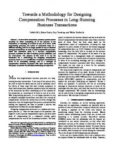
Fig. 1. Flowchart of the development activities of our tool-based methodology. Multiple inputs for an activity require synchronization; multiple outputs enable parallelization.
a taxonomy. This independence leads to two distinct design activities: entity taxonomy design and application design. These design activities, as well as the subsequent implementation and testing activities can be achieved in parallel. Figure 1 outlines the development cycle associated to our methodology and clearly illustrates the independence between these activities. In this figure, a role is associated to each development activity. Even though these activities are related, they can be achieved by distinct experts in parallel, given that these experts collaborate closely. In our development methodology, the test implementation can start in parallel with the software component implementation as test implementation only needs information provided by the architecture design and comments provided by the architect. Our approach facilitates test-driven development methodologies (e.g., agile software development [6]) where the test phase strictly precedes the implementation phase. In this way, tests guide the developers of the application. Along this development life-cycle, our methodology offers tools to assist the experts for each development activity. In particular, the specification is directly used for generating a dedicated programming support. 2.3
A Tool-based Methodology
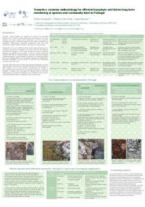
Based on this development life-cycle and its identified roles, Figure 2 depicts how our tool suite supports each
phase of the proposed methodology: Designing the taxonomy. Using the taxonomy layer of the DiaSpec language, an expert defines an application area through a catalog of entities, whether hardware or software, that are specific to a target area (stage À). A taxonomy allows separation of concerns in that the expert can focus on the high-level description of areaspecific entities. Designing the architecture. Given a taxonomy, the architect can design and structure applications (stage Á). To do so, the DiaSpec language provides an ADL layer [7] dedicated to describing pervasive computing applications. An architecture description enables the key components of an application to be identified, allowing their implementation to evolve with the requirements (e.g., varying the implementation of the light management to optimize energy consumption). Implementing entities and components. We leverage the taxonomy definition and the architecture description to provide dedicated support to both the entity and the application developers (stages  and Ã). This support takes the form of a Java programming framework, generated by the DiaGen code generator [8]. The generated programming framework guides the developer with respect to the taxonomy definition and the architecture description. It consists of high-level operations to discover entities and interact with both entities and application
4
1
2
3
D ESIGNING
THE
TAXONOMY
Maintenance and evolution. Our tool-based methodology allows for iterative development of the taxonomy and architecture. This approach allows changes in the taxonomy and architecture during late phases of the cycle.
To cope with the growing number of application areas, DiaSpec1 offers a taxonomy language dedicated to describing classes of entities that are relevant to the target application area. An entity consists of sensing capabilities, producing data, and actuating capabilities, providing actions. Accordingly, an entity description declares a data source for each one of its sensing capabilities. As well, an actuating capability corresponds to a set of method declarations. An entity declaration also includes attributes, characterizing properties of entity instances (e.g., location, accuracy, and status). Entity declarations are organized hierarchically allowing entity classes to inherit attributes, sources, and actions. An extract of the taxonomy for the Newscast area is shown in Figure 3. Entity classes are introduced by the device keyword. Note that the same keyword is used to introduce both software and hardware entities. To distinguish entity instances, attributes are introduced using the attribute keyword. Attributes are used as area-specific values to discover entities in a pervasive computing environment. They also allow the tester and the system administrator to discriminate entity instances during the simulation and deployment phases. For example, hardware entities of our taxonomy extend the abstract LocatedDevice entity that introduces the area attribute. The sensing capabilities of an entity class are declared by the source keyword. For example, the BadgeReader entity defines two data sources: badgeDetected and badgeDisappeared (lines 26 and 27). Sometimes, retrieving a data source requires a parameter. For example, the profile data source of ProfileDB entity maps a badge identifier to a user profile; in this case, the source needs to be parametrized by a badge identifier (line 14). Such parameters are introduced by the indexed by keyword. Actuating capabilities are declared by the action keyword. As an example, the LoudSpeaker declaration defines the Play action interface to be invoked by an application to play a message on loudspeakers (line 36). The play interface is defined independently in lines 39 to 41. All hardware entities inherit the OnOff action from the SwitchableDevice entity (lines 17 to 19). The taxonomy layer of DiaSpec is domain specific in that it offers constructs that map into concepts that are essential to the pervasive computing domain. This is illustrated by the source and action constructs that directly correspond to the sensing and actuating concepts. As such, our taxonomy layer offers an abstraction layer between the entity implementation and the application logic. Indeed, on the one hand, the entity developer takes an entity declaration as a specification to which an entity implementation must conform. On the other hand, the application architect can construct its specification on top
The next sections present in detail each one of these activities.
1. The DiaSpec grammar can be found on the website http:// diasuite.inria.fr/
Area Expert
Taxonomy
Application Architect
Architecture
DiaGen Code Generator
3 Entity Developer
5
class .... { .............. .............. .............. }
class .... { .............. .............. .............. }
Entities Framework
4 Application Developer
Architecture Framework
Entity Tester class .... { .............. .............. .............. }
Simulated Entities
5 DiaSim Simulator
Application Tester
Fig. 2. Development support provided by the DiaSuite tools. components. In doing so, it abstracts away from the underlying distributed technologies, providing further separation of concerns. Testing. DiaGen generates a simulation support to test pervasive computing applications before their actual deployment (stage Ä). An application is simulated with DiaSim [9], without requiring any code modification. DiaSim provides a graphical editor to define simulation scenarios and a 2D-renderer to monitor simulated applications. Furthermore, simulated and real entities can be mixed. This hybrid simulation enables an application to migrate incrementally to an actual environment. Deploying. After the testing phase, the system administrator deploys the pervasive computing application. To this end, a distributed systems technology is selected. We have developed a back-end that currently targets the following technologies: Web Services, RMI, and SIP. This targeting is transparent for the application code. The variety of these target technologies demonstrates that our development approach separates concerns into welldefined layers. This separation allows to build easily new back-ends if necessary and to smoothly apply them to already existing applications.
5
device ProfileDB { source profile as UserProfile indexed by badge as String; } device SwitchableDevice { action OnOff; } device LocatedDevice extends SwitchableDevice { attribute area as Area; } device BadgeReader extends LocatedDevice { source badgeDetected as String; source badgeDisappeared as String; } device Screen extends LocatedDevice { attribute brightness as Integer; action Display; } device LoudSpeaker extends LocatedDevice { action Play; } action Play { play(message as Audio); }
LoudSpeaker
Screen
Play
Display
AudioManager
VisualManager
action Display { display(information as Information); }
NewsSelector
ScheduleSelector
action OnOff { on(); off(); }
ClassReminder
enumeration BuildingState {OPEN, CLOSE} enumeration Topic {SPECIALTY, COURSES, EXTRACURRICULAR} structure Area { ... } structure UserProfile { name as String; language as Language; department as Department; ... } ...
DepartmentSelector
Controllers
device BuildingStatus { source state as BuildingState; }
Context components
device ScheduleDB { source todaySchedule as Schedule; }
Entities (actions)
architectural pattern commonly used in the pervasive computing domain [10], [11]. This architectural pattern is illustrated in Figure 4. It consists of context components fueled by sensing entities. These components process gathered data to make them amenable to the application needs. Context data are then passed to controller components that trigger actions on entities. Following this architectural pattern, the ADL layer of DiaSpec allows the context and controller components to be defined and the corresponding data-flow to be specified. Their definition depends on a given taxonomy, specified in the previous step of our methodology. Describing the application architecture allows to further specify a pervasive computing application, making explicit its functional decomposition.
device NewsProvider { source news as News indexed by topic as Topic; }
LanguageSelector
Proximity
buildingState
todaySchedule
badgeDetected badgeDisappeared
profile
news
BuildingStatus
ScheduleDB
BadgeReader
ProfileDB
NewsProvider
Entities (sources)
1 2 3 4 5 6 7 8 9 10 11 12 13 14 15 16 17 18 19 20 21 22 23 24 25 26 27 28 29 30 31 32 33 34 35 36 37 38 39 40 41 42 43 44 45 46 47 48 49 50 51 52 53 54 55 56 57 58 59 60 61
Legend
Fig. 3. Extract of the Newscast application taxonomy. DiaSpec keywords are printed in bold.
Sources
context data
sensed by
Entities act on
Actions
Pervasive Computing Environment
Controllers orders Architecture
Taxonomy
Fig. 4. Architectural pattern of a pervasive computing application
of this set of entity declarations, abstracting over the heterogeneity of these entities. We now present the architectural layer of the DiaSpec language, which is built on top of this taxonomy layer.
4
Architecture
Data
Action
Fig. 5. Layered architecture of the Newscast case study. Each component is described in Table 1.
raw data Contexts
Taxonomy
A RCHITECTURING
AN
A PPLICATION
The DiaSpec language provides an ADL layer to define application architectures. This layer is dedicated to an
We illustrate the ADL layer of DiaSpec with the Newscast application of our case study. The overall architecture of this application is displayed in Figure 5 and all components are described in Table 1. At the bottom of this figure are the entity sources, as described in the taxonomy. The layer above consists of the context components fueled by entity sources. These components filter, interpret, and aggregate these data to make them amenable to the application needs. Above the context layer are the controller components that receive application-level data from context components and determine the actions to be triggered on entities. At the top of Figure 5 are the entity actuators receiving actions from controller components. We now present the salient features of the DiaSpec ADL by examining a description fragment from the Newscast architecture and devoted to the display of the class schedules (see Figure 6). At the bottom of this architecture is the badge reader, declared in the taxonomy, that detects student badges in close proximity to a screen. Badge identifiers are sent to the Proximity
6
Responsibility
Type
Component
Entity (sensing)
BuildingStatus ScheduleDB BadgeReader ProfileDB NewsProvider
Provides the status of the building. Provides the schedule of each school department. Reads badges close to it. Associates badge IDs to user profiles. Provides news concerning the school.
ClassReminder Proximity
Interprets the schedule of the day to only provide the classes that start in 10 minutes. Maps detected badge IDs into user profiles. Aggregates the user profiles that surround a screen and notifies when the most representative department around the screen changes. Selects the most representative language. (Same as the DepartmentSelector) Selects the schedule to display on a screen depending on the students surrounding the screen. Selects the news to display depending on the language of the students surrounding a screen.
Context
DepartmentSelector LanguageSelector ScheduleSelector NewsSelector
Controller
AudioManager VisualManager
Entity (actuating)
Loudspeaker Screen
Plays messages on loudspeakers to inform about the next classes. Displays customized news and schedules on screens. Plays messages aloud. Displays visual information.
TABLE 1 Components of the Newscast application
1 2 3 4 5 6 7 8 9 10 11 12 13 14 15 16 17 18 19 20 21 22 23 24
context ClassReminder as Reminder { source todaySchedule from ScheduleDB; source state from BuildingStatus; } context Proximity as UserProfile[] indexed by area as Area { source badgeDetected, badgeDisappeared from BadgeReader; source profile from ProfileDB; } context LanguageSelector as Language indexed by area as Area { context Proximity; } context DepartmentSelector as Department indexed by area as Area { context Proximity; } controller VisualManager { context NewsSelector; context ScheduleSelector; action Display on Screen; [...] }
Fig. 6. Extract of the Newscast application architecture component, declared using the context keyword (lines 6 to 9). This component is responsible for maintaining the list of students, keeping an account of students leaving or entering the screen area. To do so, it processes three sources of information: one for entering badges, one for leaving badges, and one for associating badge identifiers to user profiles. These sources are declared using the source keyword that takes a source name and a class of entities. The first two sources (line 7) are bound to the same entity class, namely BadgeReader. The Proximity component signals changes in the list of students in close proximity to a screen. To produce these changes in a high-level form, it maps badge identifiers into user profiles by using the ProfileDB source (line 8). Because each list of user profiles published by the Proximity context is relative to a particular screen, the architect attaches an area to this list through the indexed by keyword. This value identifies the area surrounding the screen. The output of the Proximity component is used by both the DepartmentSelector and LanguageSelector components. These components respectively determine the dominating department affiliation and
spoken language of the nearby students. The ScheduleSelector component then combines these pieces of context information and the ScheduleDB source to decide what schedule should be displayed. To process this context on a per-area basis, all the related context components are declared as indexed by Area. The VisualManager controller component declares two sources: ScheduleSelector and NewsSelector (lines 19 to 24). It operates a screen and thus declares the Display action on the Screen entity class with the action keyword. The Newscast architecture illustrates the domainspecific nature of the DiaSpec ADL, providing the developer with pervasive computing concepts. These concepts are high level, making an architecture description concise and readable. It represents a useful artifact to share with application developers and other stakeholders. Moreover, the DiaGen code generator turns the role of this artifact from contemplative to productive, guiding the implementation of the declared components.
5
I MPLEMENTING
AN
A PPLICATION
DiaGen automatically generates a Java programming framework from both a taxonomy definition and an architecture description. After outlining the implementation of DiaGen, we briefly present a generated programming framework. This presentation is then used to explain how a developer implements entities and the application logic on top of that framework. 5.1
Programming Framework Generator
DiaGen generates a Java programming framework with respect to a taxonomy definition and an architecture description. DiaGen follows the design of typical code generators. As illustrated in Figure 7, there are three main phases: (1) the parser, (2) the type checker, and (3) the code generator.
7
Diaspec Declarations
Parser
TypeChecker
Code Generator
Programming Framework
DiaGen
Fig. 7. Structure of the DiaGen compiler. The parser relies on the ANTLR2 parser generator. Using a parser generator allows to easily refine/extend the DiaSpec language. The resulting Abstract Syntax Tree (AST) is then type-checked, ensuring for example that the inter-component communications conform to the paradigm (e.g., a controller cannot communicate directly with the source of an entity). The type-checker is implemented in Java, using visitors. Finally, the code generator is in charge of producing the programming framework from the AST. The generator is written using the StringTemplate3 engine. StringTemplate is a Java template engine for generating source code, web pages, or any other formatted text output. Our suite of tools, DiaSuite, has been released and is available for download.4
the way, we explain how the developer is guided by a dedicated programming framework. 5.3
Implementation of Entities
The compilation of an entity declaration in the taxonomy produces a dedicated skeleton in the form of an abstract class depicted in Figure 8. We now examine the generated support for each part of an entity declaration: attributes, sources, and actions. // from line 25 public abstract class BadgeReader { protected BadgeReader(Area area) { super(...); setArea(area); } // from LocatedDevice, line 22 private Area area; public Area getArea() {return area;} protected void setArea(Area area) {...} // from BadgeReader, line 26 protected void setBadgeDetected(String badgeDetected) {...} // from BadgeReader, line 27 protected void setBadgeDisappeared(String badgeDisappeared) {...} // from SwitchableDevice, line 48 public abstract void on(); // from SwitchableDevice, line 49 public abstract void off(); ... }
5.2
Generated Programming Framework
A generated programming framework contains an abstract class for each DiaSpec component declaration (entity, context, and controller) that includes generated methods to support the implementation (e.g., entity discovery and interactions). The generated abstract classes also include abstract method declarations to allow the developer to program the application logic (e.g., triggering entity actions). Implementing a DiaSpec component is done by subclassing the corresponding generated abstract class. In doing so, the developer is required to implement each abstract method. The developer writes the application code in subclasses, not in the generated abstract classes. As a result, in our approach, one can change the DiaSpec description and generate a new programming framework without overriding the developer code. The mismatches between the existing code and the new programming framework are revealed by the Java compiler. A generated programming framework also contains proxies to allow entities to be distributed over the network. This is complemented by interfaces that allow the developer to interact with entities transparently, without dealing with the distributed systems details. Finally, a programming framework contains high-level support to manipulate sets of entities easily, following the Composite design pattern [12]. We now describe the process of implementing an entity, a context component, and a controller component by leveraging a generated programming framework. Along 2. http://antlr.org/ 3. http://stringtemplate.org/ 4. http://diasuite.inria.fr
Fig. 8. The Java abstract class BadgeReader generated by DiaGen from the declaration of the BadgeReader entity (Figure 3, lines 25 to 28) Attributes. Entities are characterized by attributes. These attributes can be assigned values at runtime. Attributes are managed by generated getters and setters in the abstract class. For example, the BadgeReader entity has an area attribute (inherited from LocatedDevice, Figure 3, line 22) that triggers the generation of an implemented setArea method (Figure 8, line 12). In each subclass, the developer will use the setArea method to set the location of the badge reader. The initial value for each attribute must be passed to the generated constructor (Figure 8, line 4). Sources. An entity source produces values for context components. Support for this propagation is generated by DiaGen, allowing the entity developer to invoke these methods to fuel this process. For example, from the BadgeReader declaration and its two sources (Figure 3, lines 26 and 27), the generated abstract class (Figure 8) implements the setBadgeDetected (line 15) and setBadgeDisappeared (line 18) methods. These methods are to be called by a badge reader implementation. Actions. An action corresponds to a set of operations supported by an entity. It takes the form of a set of abstract methods implemented by the abstract class generated for an entity declaration. Each operation is to be implemented by the entity developer in the subclass. This implementation bridges the gap between the declared interface and an actual entity implementation.
1 2 3 4 5 6 7 8 9 10 11 12 13 14 15 16 17 18 19 20 21 22 23 24 25 26
8
For example, the generated BadgeReader abstract class (Figure 8) declares the abstract methods on and off (lines 21 and 24) that need to be implemented in all subclasses. The code fragment in Figure 9 is an implementation of a BadgeReader entity that uses Bluetooth to detect nearby Bluetooth devices. The BadgeReaderBluetooth implementation of the on and off methods (Figure 9, lines 10 to 14) relies on a third-party Bluetooth library. 1 2 3 4 5 6 7 8 9 10 11 12 13 14 15 16 17 18 19 20 21 22 23 24 25 26 27 28 29
public class BadgeReaderBluetooth extends BadgeReader implements BluetoothDiscoveryListener { BluetoothAutoDiscovery btDiscovery; public BadgeReaderBluetooth(Area area) { super(area); btDiscovery = new BluetoothAutoDiscovery(this); } @Override public void on() { btDiscovery.start(); } @Override public void off() { btDiscovery.stop(); } // from the BluetoothDiscoveryListener interface. // Called by BluetoothAutoDiscovery when a new device is detected @Override public void deviceDiscovered(BluetoothDevice btDev) { setBadgeDetected(btDev.getAddress()); } // from the BluetoothDiscoveryListener interface. // Called by the BluetoothAutoDiscovery when a device is not detected anymore @Override public void deviceDisappeared(BluetoothDevice btDev) { setBadgeDisappeared(btDev.getAddress()); } }
1 2 3 4 5 6 7 8 9 10 11 12 13 14 15 16 17 18 19 20 21 22 23 24 25 26 27 28 29 30 31 32 33 34 35 36 37 38 39 40 41 42 43 44
The subscribeBadgeDetected method is invoked to subscribe to the badgeDetected input source. Thus, the Proximity component is notified when a badge reader detects a new badge. When a context component declares an input source, an abstract method is generated in the abstract class for handling the data reception. This method is then implemented by the developer. In Figure 10, the onNewBadgeDetected method (lines 12 to 17) illustrates such implementation; it updates and propagates the list of profiles for a given area when a new badge is detected. When an input source is declared with indices, the generated abstract method takes these indices as parameters (e.g., the badge index of the profile input source is a parameter of the onNewProfile method). The generated framework also provides a method to pull data from an entity source. This is illustrated in Figure 10 where a ProfileDB entity is first discovered (line 36) and then invoked to obtain the user profile corresponding to a given badge (line 40). Finally, the generated abstract class provides methods to publish data uniformly, whether the consumer component is a context or a controller (line 16). public class MyProximity extends Proximity { Map profiles = new HashMap(); @Override protected void postInitialize() { allBadgeReaders().subscribeBadgeDetected(); allBadgeReaders().subscribeBadgeDisappeared(); }
Fig. 9. A developer-supplied Java implementation of a BadgeReader entity. This class extends the generated abstract class shown in Figure 8. The implementation relies on a third party Bluetooth library: deviceDiscovered and deviceDisappeared are callback methods from the BluetoothDiscoveryListener interface.
5.4
Developing the Application Logic
@Override public void onNewBadgeDetected(BadgeReaderProxy proxy, String badge) { Area area = proxy.getArea(); List list = getProfilesForArea(area); list.add(getProfile(badge)); setProximity(list, area); } @Override public void onNewBadgeDisappeared(BadgeReaderProxy proxy, String badge) { // similar to onNewBadgeDetected, but removes // instead of adding to the list } private List getProfilesForArea(Area area) { List list = profiles.get(area); if (list == null) { list = new ArrayList(); profiles.put(area, list); } return list; }
The implementation of a context or controller component also relies on generated abstract classes. The development of the application logic thus consists of sub-classing the generated abstract classes.
5.4.1 Implementation of context components From a context declaration, DiaGen generates programming support to develop the context processing logic. The implementation of a context component processes input data to produce refined data to its consumers. 45 The input data are either pushed by an entity source46 47 or pulled by the context component. Both modes are48 provided to the developer for each source declaration of the architecture. The code fragment in Figure 10 presents the implementation of the Proximity context (from Figure 6, lines 6 to 9). This is done by extending the corresponding generated abstract class named Proximity. This implementation starts by discovering all available badge readers using the allBadgeReaders method (line 7). This method is provided by the Proximity abstract class.
private UserProfile getProfile(String badge) { // gets a handler on the ProfileDB ProfileDBProxy profileDB = allProfileDBs().anyOne(); // asks the ProfileDB about a profile for // the current badge return profileDB.getProfile(badge); } @Override public void onNewProfile(ProfileDBProxy proxy, UserProfile newValue, String badge) { // nothing to do here, this context is not // interested by notifications from the ProfileDB } }
Fig. 10. A developer-supplied implementation of the Proximity context. 5.4.2 Implementation of controller components A controller component differs from a context component in that it takes decisions that are carried out by invoking entity actions. A controller declaration explicitly
9
states which entity actions it controls. This information is used to generate an abstract class for each controller component. This abstract class provides support for discovering target entities and for invoking their actions. From the declaration of the visual manager controller (Figure 6, line 19), DiaGen generates an abstract class named VisualManager. Figure 11 shows an implementation for this controller. When the NewsSelector context produces a new value, the onNewNewsSelector method is invoked (line 4) in the MyVisualManager implementation. The method starts by discovering screens present in a given area (line 5). It then displays the news on these screens (line 6) by invoking the remote method display. This ability to discover and command screens from the visual manager comes from the architecture declaration (Figure 6, line 22). 1 2 3 4 5 6 7 8 9 10 11 12 13 14
public class MyVisualManager extends VisualManager { @Override public void onNewNewsSelector(News news, Area area) { ScreenComposite screens = discover(screensWhere().area(area)); screens.display(new Information(news.content)); } @Override public void onNewScheduleSelector(Schedule newValue, Area area) { // similar to onNewNewsSelector } }
Fig. 11. An implementation of the VisualManager controller. After having presented the programming support given by a generated framework, we focus on a key mechanism to cope with dynamicity, namely, entity discovery. 5.5
Entity Discovery
Our dedicated programming framework provides support to discover entities based on the taxonomy definition. Entity discovery returns a collection of proxies for the selected entities. This collection is encapsulated in a composite object that gathers a collection of entities [12]. The composite design pattern applied to screen proxies is illustrated in Figure 12. An example of such collection, ScreenComposite, is returned in line 5 of Figure 11. Thanks to this design pattern, the developer can process all elements of the collection either explicitly by using a loop, or implicitly by invoking a method of the composite, which is part of the generated programming framework. Line 6 in Figure 11 is an example of an implicit iteration. To help developers express queries to discover entities, DiaGen generates a Java-embedded, type-safe DomainSpecific Language (DSL), inspired by the work of Kabanov et al. [13] and by fluent interfaces introduced by Fowler [14]. Existing works often use strings to express queries, which defer to runtime the detection of errors in queries. In our approach, the Java type checker ensures that the query is well-formed at compile time. This strategy contrasts with other works where the Java language
MyVisualManager
IScreen display(String)
ScreenProxy display(String)
ScreenComposite
children
display(String)
for (IScreen s : children) s.display(message);
Fig. 12. Application of the composite design pattern to screen proxies.
is augmented, requiring changes in the Java compiler and integrated development environments, as illustrated by Silver [15] and ArchJava [16]. A method suffixed by Where is available for each device that can be discovered. These methods return a dedicated filter object on which it is possible to add filters over attributes associated with the entity class. For example, the VisualManager abstract class defines a screensWhere method that returns a ScreenFilter. This filter can be refined by adding a filter over the area attribute inherited by the Screen in the taxonomy. This is done by calling the area() method defined in the generated ScreenFilter class. The parameter to this method is either an Area value or a logical expression. If an Area value is passed, the discovered entities are those with an area attribute equals to the passed value. An example of the use of a value is given in the MyVisualManager class shown in Figure 11. The onNewNewsSelector method selects screens to operate. The call to screensWhere (line 5) restricts the selection to screens located in the area where the news should be published. If a logical expression is chosen, the attributes of the selected entities hold with respect to the logical expression. A logical expression is made of relational and logical operators. For example, the following query selects screens that are either located in room 1 or 2: Area room1, room2; ... discover( screensWhere().area(or(eq(room1),eq(room2))) );
New methods can be defined to further enhance the expressiveness of the query language. Our approach allows developers to specify filters for more than one attribute, as shown in the following example. Integer minSize; Area room1; ... discover( screensWhere().area(room1).size(gt(minSize)) );
10
This query selects all screens that are both in room 1 and provide a specified minimum size. Our current implementation does not allow logical expressions across attributes. For example, it is not possible for a query to specify that a device must have a particular value for an attribute or another value for another attribute. We are working on this limitation. This embedded DSL is both expressive and concise. It plays a key role in enabling the developer to handle the dynamicity of a pervasive computing environment without making the code cumbersome. 5.6 Interaction Modes An application interacts with an entity either to carry out an action or access data. A generated programming framework supports the former case with the command interaction mode. The latter case is supported by both a pull and push mode. Command. A command is a one-to-one asynchronous interaction mode, similar to a remote procedure call. The developer can pass arguments to a command according to signatures included in the DiaSpec taxonomy. Because a command is limited to triggering actions provided by entities, it does not return a value, as could a remote procedure call. An example of command invocation is given in line 6 of Figure 11. Instead of encoding invocation errors with a return value, we propose a declarative approach at the architecture level [17]; this approach is outlined in Section 11. Pull. A context can fetch data from entities and other contexts. To achieve these interactions, the pull mode provides a one-to-one synchronous interaction mode with a return value. Accessing data from an entity then consists of invoking the appropriate methods of the entity proxy returned by the entity discovery mechanism. For each index of the data source, a parameter is required for the method invocation. This is exemplified by line 40 in Figure 10. Push. This mode corresponds to the asynchronous publish/subscribe paradigm. When a device or a context needs to push an event (e.g., whenever it changes), it calls a set method implemented in its abstract class. This is illustrated by the MyProximity context (Figure 10) that publishes a list of user profiles located in a given area (line 16) through a call to the setProximity method. An event value is received by all entities that have subscribed to the event type. A subscription method is generated in an abstract class for each entity source while subscription to context components is automatic. The management of subscribers and the propagation of events are supported by the generated programming framework, further easing the development process.
6
T ESTING
A
P ERVASIVE C OMPUTING S YS -
TEM
As in any software engineering domain, testing pervasive computing applications is crucial. However, this
domain has specific requirements that prevent generic testing tools from applying to pervasive computing applications [4]. Indeed, pervasive computing applications interact with users and with the physical environment. Generic software testing tools do not cope with neither the simulation of the physical environment, nor the simulation of users in this physical environment. Coping with these requirements makes the testing of pervasive computing applications challenging. In fact, only a few existing development approaches in the pervasive computing domain address testing: existing development approaches often assume that the system is partially or fully deployed. However, deploying a pervasive computing application for testing purposes can be expensive and time-consuming because it requires to acquire, test, and configure all equipments and software components. Furthermore, some scenarios are difficult to test because they involve exceptional situations such as fire. To cope with these issues, DiaSuite includes a simulator for pervasive computing applications, named DiaSim. This tool is integrated in our methodology, leveraging declarations provided at earlier development stages. It provides support to simulate the physical environment and execute pervasive computing applications developed in DiaSuite. DiaSim leverages the abstraction layer of the generated programming framework that allows entities to be operated regardless of their nature (e.g., actual or simulated). This abstraction layer allows the simulation of these applications without requiring any changes in the application code. The modeling of the physical environment is described in Section 6.1. DiaSim provides an editor to create simulation scenarios to test pervasive computing applications. The creation of a simulation scenario is examined in Section 6.2. Finally, in Section 6.3, the DiaSim runtime platform is presented. 6.1
Modeling the Environment
The first step to simulate a pervasive computing application is to model the physical environment. This model can be used to test multiple pervasive computing applications. The modeling of the physical environment is realized in a graphical editor. This editor allows to define the layout of a physical environment, including structural characteristics (e.g., walls). Figure 13 shows the simulated school building that we modeled for testing the Newscast application. In this example, an area has been defined for each room, corridor, and hall of the simulated school building. Then, using a DiaSpec taxonomy, the tester defines and places the simulated entity instances in the model of the physical environment. Figure 13 illustrates the configuration of simulated entity instances for testing the Newscast application. In this example, simulated loudspeakers, screens, and badge readers are placed in the main school hall. Simulated loudspeakers are also placed in each corridor. Finally,
11
Fig. 13. DiaSim environment editor. The DiaSim editor is parameterized by an entity taxonomy. The entities defined in the taxonomy are displayed on the left panel of the graphical user interface. The entities can be dragged and dropped on the central panel to add simulated entity instances into the simulated environment.
simulated people are added to the simulation using the editor. We can assign properties to each simulated person. For testing the Newscast application, we assign a badge ID to each simulated person. The badge ID property is then used during the simulation by the simulated badge readers when publishing a badge detection or badge disappearance event.
environment stimuli allows to test an application in a simulated environment. Defining the evolution of the physical environment consists of defining these simulated environment stimuli. The tester can either define these environment stimuli during the edition using a stimulus library, or he can program them using a simulation programming support. These two sorts of support also apply for defining the behavior of simulated entities.
6.2
Stimulus and entity behavior library. During the edition, for each stimulus needed in a simulation scenario, the tester defines its refreshment rate and how its values evolve. As an example, the luminosity value of an outside area could be refreshed every second and vary every hour. To ease stimulus configuration, a library of commonly used stimuli is provided. For instance, this library allows to easily create sinusoidal stimuli. A simple simulation of outside temperature and luminosity can be modeled as sinusoids. Another library is provided to the developer with basic behaviors for entities. For example, one behavior consists in making a sensor periodically publish values. In the Newscast application, we used
Defining the Simulation Scenarios
As the scope of pervasive computing applications increases, so does the range of scenarios to test. DiaSim provides support to define these scenarios. A simulation scenario consists of a series of evolutions of a physical environment and simulated entity instances. An evolution corresponds to a change in the simulated physical environment at a specific time. During the simulation, these changes are emitted by the simulator and processed by the simulated entity instances. In a pervasive computing application, data sources come from sensing stimuli from the physical environment; the collected data are used for context processing. Simulating the
12
this library of behaviors for the simulated badge readers. The chosen behavior simply forwards simulated stimuli. Thus, when a simulated badge reader receives a badge detection or badge disappearance stimulus, it forwards this information to the Newscast application. Simulation programming support. Yet, new stimuli and behaviors can be introduced; this development is facilitated by a simulation programming support. This programming support provides a generic StimulusProducer class that the tester can use to create his own stimulus producers. As well, the tester can develop his own entity behavior by extending the abstract class provided in the generated programming framework for this entity. In the Newscast case study, we use this simulation programming framework to produce badge detection and disappearance stimuli when simulated people move around simulated badge readers. Figure 14 presents the implementation of the class that publishes badge detection and disappearance stimuli. This class extends DiaSimAgentModel. The DiaSimAgentModel class is provided by the simulation programming framework and provides programming support for handling the simulated people of the simulation. In this example, it is used to be notified when a simulated agent enters or leaves the detection area surrounding a badge reader. Two stimulus producers are created in this class: badgeDetectedProducer (Figure 14, line 11) and badgeDisappearedProducer (line 13). The simulation programming support allows to be notified when an agent moves by implementing the AgentListener interface. When an agent moves, the agentMoved method is called (Figure 14, line 28). When an agent enters the detection area of a badge reader, a badge detection stimulus is published (Figure 14, line 36). Likewise, when an agent leaves the detection area of a badge reader, a badge disappearance stimulus is published (Figure 14, line 44).) In this example, the detection range of the simulated badge readers is set to 5 meters (Figure 14, line 3). Further simulation support. An ongoing work on DiaSim is to create physically accurate simulation of the physical environment [18]. This work consists of coupling DiaSim with the Acumen DSL [19]. Acumen allows to describe continuous systems with mathematical equations. For example, temperature is a physical characteristic that can be described as a continuous system with Acumen. The simulated environment stimuli are computed by Acumen, allowing a physically accurate simulation of the environment. Once a scenario is defined, it is executed by the DiaSim runtime platform. 6.3
Running the Simulation Scenarios
Simulation scenarios are executed in the DiaSim runtime platform. This platform includes a 2D-graphical renderer, based on Siafu [20], to monitor the simulation. The simulation renderer is illustrated in Figure 15. The
public class MyAgentModel extends DiaSimAgentModel implements AgentListener { private private private private
static int DETECTION_RANGE = 5; Map detectedAgents; StimulusProducer badgeDetectedProducer; StimulusProducer badgeDisappearedProducer;
public MyAgentModel(World world) { super(world); Source badgeDetectionSource = new Source( " BadgeReader " , " badgeDetected " , " S t r i n g " ); badgeDetectedProducer = new StimulusProducer(badgeDetectionSource); Source badgeDisappearanceSource = new Source( " BadgeReader " , " badgeDisappeared " , " S t r i n g " ); badgeDisappearedProducer = new StimulusProducer(badgeDisappearanceSource); detectedAgents = new HashMap(); } @Override public List createAgents() { List agents = super.createAgents(); for (DiaSimAgent a : agents) { agent.addAgentListener(this); } return agents; }
@Override public void agentMoved(Agent agent, String location) { String id = agent.getProperty( " badgeId " ); if (!detectedAgents.contains(agent)) { /* This agent has not been detected yet by a badge reader. We check if he has entered the detection area of a badge reader */ for (DiaSimDevice d : getDevices()) { if (d.getType().equals( " BadgeReader " ) && agent.distanceFrom(d.getPosition()) < DETECTION_RANGE) { detectedAgents.put(agent,d); badgeDetectedProducer.publish(id,location); } } } else { /* This agent has already been detected by a badge reader. We check if he has left the detection area of this badge reader */ DiaSimDevice badgeReader = detectedAgents.get(agent); if (agent.distanceFrom(badgeReader.getPosition()) > DETECTION_RANGE) { detectedAgents.remove(agent); badgeDisappearedProducer.publish(id,location); } } } }
Fig. 14. Implementation of the MyAgentModel class used in the Newscast application simulation. This class is responsible for publishing badge detection stimuli when simulated people come near a badge reader. It is also responsible for publishing badge disappearance stimuli when simulated people leave the surroundings of badge readers. simulated entities are displayed in the environment representation and messages appear above the entities when sensing or actuating is performed. Fine-grained simulation can be achieved by manually injecting stimuli during the simulation and plotting trajectories to move simulated persons. Finally, a tested application can be executed in hybrid environments, combining simulated and real entities. Hybrid simulation is a key feature to successfully transition to a real environment: it allows real entities to be added incrementally in the simulation, as the implementation and deployment progress.
7 D EPLOYING S YSTEM
A
P ERVASIVE
C OMPUTING
A pervasive computing application is distributed by nature and thus depends on the chosen distributed systems technology. When no abstraction layer is provided to the developer, the application code embeds distributed
1 2 3 4 5 6 7 8 9 10 11 12 13 14 15 16 17 18 19 20 21 22 23 24 25 26 27 28 29 30 31
32 33 34 35 36 37 38 39 40
41 42 43 44 45 46 47 48
13
Fig. 15. DiaSim scenario renderer. The simulated environment is displayed in the left part of the graphical user interface. The red popups transparently displayed above the simulated entities indicate that the entity has realized an interaction. More information about the simulated people and simulated entities can be found on the right of the graphical user interface.
systems operations, creating dependencies to the underlying technology and obfuscating the code. Our tool-based methodology makes it possible for application code to abstract away from the underlying distributed systems technologies, deferring to the DiaSuite back-end the mapping to a particular platform. This strategy makes the application code portable across distributed systems technologies without any change in the implementation. When the pervasive computing application is deployed, a distributed systems technology is selected. Four distributed systems technologies are currently offered, targeting Web Services [21], SIP5 , and RMI [23]. Each of these technologies provides specific features and mechanisms with various benefits for the 5. SIP stands for Session Initiation Protocol [22]. It is a de facto standard for modern telephony.
development of pervasive computing applications. For example, RMI is well-suited for testing because it only requires a lightweight infrastructure. SIP is well-suited for pervasive computing systems that revolve around telephony. We are working on a new back-end mechanism that allows the entities to declare which distributed systems technology they support. This back-end will make it possible to mix several communication protocols in the same application, depending on what is supported by the entities. Finally, deployment currently requires writing Java code to instantiate the needed entities. We believe this could be made easier by leveraging an existing deployment technology such as OSGi [24]. In particular, we plan to generate OSGi bundles for each entity to let OSGi handle entity life-cycles.
14
8
M AINTENANCE
AND
E VOLUTION
Maintenance and evolution are important parts of the development of any software system [3]. It is even more important in the pervasive computing domain where new entities may be deployed or removed at any time and where users may have changing needs. To cope with maintenance and evolution of such applications, our tool-based methodology allows an iterative development of a pervasive computing application. This is illustrated in Figure 16. 8.1
Evolution of the Taxonomy
The taxonomy is likely to change in a stage subsequent to the programming framework generation (e.g., during the application implementation or after deployment). Applying these changes requires the programming framework to be regenerated. When the newly-generated programming framework is supplied to the developers, the IDE automatically points to code locations where changes are required, as is done with any ill-typed Java programs. We now review the main evolution cases. Declaring new entities. A new entity can be declared in the taxonomy at any time. This evolution does not require any code changes beyond the implementation of the generated abstract class for the entity and deployment of its instances. Extending an entity. An entity declaration can be extended with additional functionalities and attributes. As in a class hierarchy, these extensions do not require any changes in the existing code besides the implementation of these new functionalities. Removing an entity or one of its functionalities. An entity declaration or an entity’s functionality can be removed by the area expert. Such a change requires the modification of the architecture and the regeneration of the programming framework. The new programming framework triggers Java compile-time errors in the implementation code. These errors concern the entity developers and potentially the application developers. 8.2
Evolution of the Architecture
Similarly, an architect may want to change the context and controller component descriptions of the architecture. Again, this requires a regeneration of the programming framework that can lead to compile-time errors to be resolved by the application developer. Adding a new context or controller. New context and controller declarations can be added. This does not require any code changes beyond the implementation of the newly generated abstract classes. Adding a new input source. A context or controller declaration can be added a new input source or context, solely requiring the implementation of the newly generated abstract methods.
Removing an input source. A context or controller declaration can be removed an input source or context. In this case, code that deals with this input source becomes dead. The Java compiler detects this situation and reports it as an error, requiring the developer to remove the dead code.6 Changing a context type. A context type can be changed. In this case, the implementation of this context as well as implementations of subscribers of this context have to be fixed accordingly. Again, the Java compiler displays meaningful errors to guide the developer. Adding or removing actions. A controller can be added or removed device actions. Removal of a device action in a controller leads to compile time errors where the action is used. An action added to a controller does not affect the controller implementation in any way, but new methods are available to be used.
8.3
Changing the Deployed System
Our system supports basic runtime changes. Plugging and unplugging entity instances. New entity instances can be added, or removed without requiring any changes in the application code. New instances are registered into the framework and become immediately available via entity discovery. Unplugged entities are detected and automatically made unavailable to entity discovery. Implementing and plugging new entity implementations. An entity developer can implement a new kind of entity without requiring any changes. A system administrator can deploy new instances of this implementation without restarting the system. This section presented how our approach supports changes in the taxonomy and architecture, late in the development process. To further enhance this process, we believe we could provide the architect and area expert with refactoring tools to ease changes in developer’s code. This could be done in different ways, the simplest being the generation of migration documentation. More challenging solutions could propagate refactorings from the architecture and taxonomy to the implementation.
9
E VALUATION
OF OUR METHODOLOGY
In this section, we conduct an evaluation of our methodology. To do so, we explore three aspects: (1) expressiveness, evaluating the scope of this methodology, (2) usability, estimating the intuitiveness of the tools, and (3) productivity, measuring development time, code quality, and reusability. 6. This feature depends on the @Override annotation introduced in Java 5.
15
modified implementation
implementation
Initial specification
Initial generated framework
1
2
3
Modified specification
Compile-time error
4
5
6
Fig. 16. Changes in the specifications are possible even after framework generation. They often trigger Java compiletime errors that IDEs will report. In stage À, the architect writes an initial specification. In stage Á, a programming framework is generated from the specification and a developer starts implementing on top of it in stage Â. In stage Ã, the architect modifies the specification. A new programming framework is generated in stage Ä. This new framework replaces the previous one; this triggers Java compile-time errors in existing implementations. In stage Å, the developer is guided by the compile-time errors to apply the changes of the architect to the implementation.
9.1
Expressiveness
We study the expressiveness of the DiaSpec specification language by evaluating the scope of the underlying architectural pattern. This expressiveness is evaluated by developing a wide range of applications in multiple areas. We now describe some of them. In-lab deployment: To show that our framework is operational, we have deployed several applications in a dedicated room of our lab. The first application is an anti-intrusion system. It is responsible for securing a room with password-protected lockers, motion detectors, and alarms. When an intrusion is detected, the application takes a photo of the intruder and sends it to a supervisor along with information about the intrusion [25]. The second application is a multimedia-content alert system that informs users about their preferred TV programs. The third application is a peer-to-peer document sharing system that requires user identification through various means (e.g., RFID badges and fingerprint). The fourth application is an intranet web-server monitoring prototype. This monitoring application logs the profiles of the web server users and emails the server administrators in case of intrusion. Finally, the Newscast application described in this paper has been deployed in our lab and used in several demos [9], [25]. A real-size case study: We applied our tool-based methodology to a real-size case study: the management of a 13,500-square-meters building hosting an engineering school. Six pervasive computing applications, including the Newscast application, were developed for this case study. These applications cover several pervasive computing areas. The light and air management applications relate to the building automation area. The fire management application pertains to the emergency management area. Finally, the access control and antiintrusion applications relate to the security area. Table 2 gives, for each application of this case study, the number of elements for each type of declarations: entity classes, context components, and controller components. In total, the case study involves 36 classes of entities,
Application Newscast Light Management Air Management Access Enforcer Anti-Intrusion Fire Management
class
Entity source
action
7 5 7 4 6 7
6 4 5 5 4 4
2 2 4 1 2 3
Context
Controller
6 3 6 3 4 2
2 1 2 1 2 1
TABLE 2 Metrics on our case study
28 data sources, 14 action definitions, 24 context components, and 9 controllers. The DiaSpec taxonomy consists of 200 lines of code (LOC), the architecture 130 LOC, the generated framework 7000 LOC, and developer-supplied Java code 3000 LOC. We observe that to cover realistic areas, the number of entity classes is low: up to 7. This makes the artifacts of our tool-based methodology manageable for the stakeholders of a development project; they are an effective vehicle to expose and share design decisions. This case study showed that most of the application logic is realized in the context components. Indeed, the layers of our architecture pattern isolate the context calculation from its use for controlling the environment. This layered architecture simplifies the implementation of the controllers and allows the information processing to evolve independently from the control. As a consequence, there are few controllers per area (between one and two), in contrast to the number of contexts (four, on average). The engineering school building is simulated using DiaSim. In this simulation, over 400 entity instances and 300 occupants are simulated (e.g., staff and faculty members, students, and visitors) with various behavioral patterns. We are planning on deploying part of the applications in-situ. We have already started to make unitary tests of equipments and software entities, thanks to the incremental capability of DiaSuite. We notice that our case study was modeled with few declarations of entities, contexts, and controllers; and yet
16
Phase
Nature of the task
Design Implementation Testing
DiaSpec specification Extension of the generated fwork. DiaSim simulation
% students full part 100% 60% 30%
0% 40% 0%
Avg. time 2h 5h 1h
TABLE 3 Results of a lab involving 60 undergraduate students.
this model scaled up to a rather large simulation scenario, involving numerous entities, building occupants, and simultaneously running applications. During the development of our approach, we have implemented various applications covering numerous areas including home/building automation [8], [25], multimedia adaptation, IP telephony [26], [27], and healthcare [28]. The wide spectrum of areas covered shows the expressiveness of our methodology in the context of pervasive computing. 9.2
Usability
We have been using DiaSuite for a course on software architectures for three years. This course included an 8hour lab that consisted of twenty groups of three undergraduate telecommunication students (equivalent to the master’s level) who had never used DiaSuite. Furthermore, these students had only followed an introductory course on Java a year before the software architecture course and had no prior experience in software design or pervasive computing. The goal of the lab was to develop a Newscast application from a diagram similar to that of Figure 5. Using the diagram, the students did not have to find the decomposition of the application into DiaSpec components, simplifying the design stage. They had to (1) determine appropriate types for the entity sources and contexts, (2) translate the diagram into DiaSpec, and (3) implement the application. We intentionally gave very sparse information about DiaSpec and the generated programming framework, to determine to what extent the language and generated framework were in themselves able to guide the architecture and development. The results of this lab are presented in Table 3. All student groups have managed to design a DiaSpec architecture in conformance with the provided diagram. In general, students only required explanations about the role of each component type (entity, context, and controller) and the interactions between these types. During the whole evaluation, DiaGen produced error messages that were clear enough to require no additional information from the instructor. At the end of the 8-hour lab, 60% of the groups managed to develop a working implementation where all provided unit tests passed while the remaining 40% provided a partial implementation where most of the unit tests passed. 30% of the students went beyond the
assignment by configuring and testing their application using the DiaSim simulator. This first experience demonstrates that students with modest knowledge in software engineering are able to efficiently use DiaSpec in a short time. This first usability evaluation is preliminary. We plan to conduct empirical usability studies with professional software developers. We believe that professional software developers with a background in Java and Eclipse will provide a direct feedback on our approach, without the interferences observed with our students due to their lack of acquaintance with the programming tools. Furthermore, we have noticed that DiaSuite helps decomposing the development effort into clearly defined task assignments: each stakeholder needs only a local knowledge of his task. We would like to conduct further studies on this aspect to assess its impact in practice. 9.3
Productivity
One of the benefits of DSLs is to enhance productivity [29]. In the following, we show how our methodology reduces development time, enhances code quality, and promotes reusability. We believe these three dimensions give an insight as to how our methodology improves productivity. Development time: Initial development time is directly proportional to the size of the written code. Automatic program generation aims to reduce the code to be written and thus to reduce development time. We measured the quantity of the generated code in several applications we developed. Our measures reveal that nearly 80% of the project code base is generated, the implementation accounts for 17%, the rest being the declarations in DiaSpec. Importantly, these measures are useful only if the generated code is actually executed. Otherwise the generated code can be arbitrarily large without impacting development time. We measured the coverage of the framework code during a number of executions of these applications, using the CodeCover testing tool.7 On average, 70% of the generated framework is actually executed. We studied the parts of the framework that are not executed and found that most of them are either error handling code or features unused by the application logic. Code quality: A program with a good code quality is a program that evolves and is maintained with ease. Code quality is critical as maintenance of a software system accounts for more than 85% of the total cost of an application [30]. We measured code quality of implementations from developers allowing us to assess the usefulness of our approach in making developers write high quality implementations. We used Sonar8 to measure the code quality of three applications: a web-server monitoring application, an anti-intrusion system, and the 7. http://www.codecover.org/ 8. http://www.sonarsource.org/
17
Newscast application presented in this paper. To do so, we used various criteria, as provided by Sonar, including code duplication, rules compliance, code coverage, and code complexity. As an example, the code complexity is measured using the well-known cyclomatic complexity metric as defined by McCabe [31]: this metric measures the number of linearly independent paths in a source code. The implemented code for the three projects has an average cyclomatic complexity of 3. McCabe notes that “code in the 3 to 7 complexity range [...] is quite well structured”. A complexity greater than 10 indicates very poor code quality, which hampers maintenance and thus productivity. The other criteria, as offered by Sonar, present results indicating an overall good quality of written source code. These results, associated with the small percentage of code written manually, reveals that our generated programming framework guides the developers through a well-structured and easy-to-maintain code. Reusability: Our approach promotes reuse of the specifications and implementations across applications. An entity specification and its associated implementation can be packaged for later reuse. To promote cross application reuse, we have developed DiaStore, a web application that allows to easily download and deploy new DiaSpec applications in the spirit of the Apple’s App Store9 (see Figure 17). Using the declarations from the taxonomy, DiaStore indicates the entities currently deployed at home and checks whether the entity requirements of a new application are fulfilled. This approach encourages the sharing of entities between applications. We have also noticed that the DiaSpec architectural pattern encourages context reuse. Specifically, intraapplication reuse arises for applications sharing refined sensed data via context components. This first evaluation of our tool-based methodology is promising. The scope of the applications embraces most of the pervasive computing area. The intuitiveness of the generated framework has been validated with students who managed to develop an entire Newscast application, without any API documentation, solely using the IDE completion. Finally, the productivity gain has been evaluated through several criteria measuring development time, code quality, and reusability.
10
R ELATED
WORK
In this section, we present a comparison study of the existing approaches for developing pervasive computing applications. This study addresses each stage of the development cycle, namely, design, implementation, testing, deployment and evolution/maintenance. We characterize the existing development approaches and illustrate each of them with a representative example. The results of this comparison are shown in Table 4. The degree of support for each development 9. http://www.apple.com/iphone/features/app-store.html
Fig. 17. DiaStore, a web application to share and deploy new DiaSpec applications. Design. Implem. Test. Deploy. Evol./Mainte. DiaSuite PervML [1] ArchFace [32] Context Tk. [10] Olympus [33] Player/Stage [34]
++++ ++ ++ + +
+++ ++++ ++ ++ ++ ++
++ +
+++ ++++
++
+++ +
+++ ++++
TABLE 4 Comparison of the support provided by representative approaches throughout the development cycle.
stage is rated from “+” to “++++”: “+” corresponds to low-level support, such as guidelines, whereas “++++” corresponds to highly customized support or complete automation of the task. When no support is provided by an approach, no rating is given. In the remaining of this section, we first present the existing development methodologies that provide support for the entire development cycle. Then, we present the development approaches that target particular stages of the development cycle. 10.1
Model-Driven Engineering
Model-Driven Engineering (MDE) uses models and model transformations to specify software architectures and generate implementations [35]. The goal of these MDE approaches is to raise the abstraction level in program specifications and generate a working implementation from such a specification. UML 2.0 (Unified Modeling Language) has been widely accepted as an architecture modeling notation [36] and as a second-generation ADL [37]. Various development environments, relying
18
on UML and MDE, have been proposed (e.g., Enterprise Architect [38]). These development environments cover the complete development life-cycle. However, they do not target the specific features of pervasive computing, leaving the customization work to the architects and the developers. PervML [1], listed in Table 4, customizes the MDE approach with respect to the domain of pervasive computing by proposing a conceptual framework for contextaware applications. This conceptual framework relies on UML diagrams to model pervasive computing concerns. For example, services are modeled with class, sequence, and state transition diagrams, while locations are modeled with package diagrams. Even though the conceptual framework proposed by PervML is domain specific, it relies on generic notations and generic tools, incuring an overhead for designers. In contrast, DiaSpec designers only manipulate domain-specific concepts and notations (e.g., entities, context and controller components), facilitating the design phase. PervML, along with most MDE-based approaches, require designers to directly manipulate OCL and UML diagrams. As reported in the literature, this manipulation becomes “enormous, ambiguous, and unwieldy” [39], [40], [41]. In practice, these approaches demand an in-depth expertise in MDE technologies. For the design phase, PervML is rated “++”. From UML diagrams, PervML provides a dedicated suite of tools to generate a complete implementation. This approach is thus rated “++++” for the implementation stage. Using UML diagrams allows to leverage developers’ knowledge and existing tools, such as the Eclipse Graphical Modelling Framework (GMF) and the OSGi deployment model; it is thus rated “++++” for the deployment. PervML offers rudimentary testing support, based on device simulation; this phase is rated “+”. By leveraging MDE development environments, the evolution of an existing PervML application only requires to modify its model and to re-generate the implementation. This evolution capability results in rating the corresponding PervML stage “++++”. 10.2 Architecture Description Languages Architecture Description Languages (ADLs) are used to make explicit the design of an application. Most ADLs are dedicated to analyzing architectures; they provide little or no implementation support. Archface [32] is the most recent instance of this line of work (Table 4). It is both a general-purpose ADL and a programminglevel interface. It proposes an interface between design and code. However, the design support provided by Archface is generic. Furthermore, Archface requires the software architect to have some knowledge about the implementation layer to be able to express the interface part of a design. In contrast, our approach is domain specific and thus allows domain experts to design their architecture
without implementation knowledge. The design is then used to generate dedicated programming support for the developer. For example, DiaGen generates dedicated programming support to discover entities based on the taxonomy definition. In Archface, a design is directly mapped into programming-level interfaces, ensuring the conformance between the design and the implementation. However, unlike our approach, Archface does not provide dedicated programming support. Taking into account these limitations, Archface is rated “++” for both the design and implementation stages. The other development stages are not covered by this approach. 10.3
Context management middlewares
Numerous middlewares have been proposed to support the implementation of pervasive computing applications. Schmidt et al. [42], Chen and Kotz [11], and Dey et al. [10] have proposed middleware layers to specifically acquire and process context information from sensors. The Context Toolkit proposed by Dey [10] illustrates this approach in Table 4. Henricksen et al. take this approach one step further by introducing a language to model the computation of context information [43], [44]. However, none of these middlewares provide tool support for the design phase, they only provide design guidelines; Context Toolkit is thus rated “+”. Although, context management middlewares provide programming support for acquiring and processing context information from sensors, they do not address the other activities pertaining to a pervasive computing application (e.g., device actuation). Because of this limitation, the programming support of this approach is rated “++”. The other development stages are not covered by these middlewares. 10.4
Programming Frameworks
The programming framework approach has been applied to the domain of pervasive computing to facilitate the development of applications by raising the level of abstraction. A representative example is Olympus [33], included in Table 4. Olympus offers limited support for the design stage: it mainly consists of guidelines related to the concept of Active Space. This stage is rated “+”. An Active Space represents a physical space enriched with sensors and actuators. Virtual entities of an Active Space can be described programmatically using highlevel programming interfaces, allowing the developer to focus on the application logic. However, the programming support is not dedicated to a specific description of an Active Space. Thus, the application logic is implemented using generic datatypes, making the implementation error-prone. In comparison, DiaSuite provides datatypes to the developer that are dedicated to the application to be implemented. Olympus implementation support is rated “++”. The high-level nature of the description of an Active Space allows to reuse the same program across pervasive
19
computing environments, easing the deployment stage ; it is thus rated “++++”. 10.5
Simulators
Few simulators are dedicated to the testing of pervasive computing applications. Stage and Gazebo are simulators dedicated to the Player programming framework and have been used to simulate a sensor-enriched kitchen [45]. Player is a programming framework and a middleware created in the robotics domain and widely recognized as a standard for robot programming [34]. Other pervasive computing simulators include Ubiwise [46] and Tatus [47] that are built upon 3D firstperson game-rendering engines; they allow the user to have a focused experience of a simulated environment. However, these simulators are difficult to extend: the game-rendering engine has to be modified to add new sensors and actuators, or to simulate arbitrary context data. The PiCSE simulator addresses the problem of extensibility by providing generic libraries to create sensors and actuators [4]. In Table 4, the Stage simulator combined with the Player programming framework illustrate this compound approach. Player allows to specify interfaces that define how to interact with robotic sensors, actuators and algorithms. However, this design support is very limited as it does not cover the design of other application components. For instance, it does not allow to design the controllers that coordinate robotic devices. Thus, Stage is rated “+” for the design phase. The Player programming support enables to develop a wide range of robotic applications. However, this programming support only targets the robotic area, resulting in a “++” rating. Player applications can be simulated in a 2D graphical environment using Stage, or in 3D using Gazebo. However, both simulators only target the simulation of mobile robots; their testing support is rated “++”. These simulators provide guidelines to deploy applications but do not address evolution; they are rated “+” for the deployment stage. Moreover, they have to be manually specialized for every new application area. In contrast, DiaSim relies on the DiaSpec descriptions to automatically customize the simulation tools (i.e., the editor and the renderer). 10.6
Summary
The comparison in Table 4 first shows that DiaSuite provides a comprehensive support for the design and programming stages, compared to the existing approaches. It also shows the support for the testing, deployment, and evolution stages can be improved. To do so, we plan on leveraging existing technologies that focus on these stages. For example, to improve the deployment and runtime evolution support, we are working on leveraging OSGi, as is done by PervML.
11
C ONCLUSION
In this paper, we presented DiaSuite, a tool-based methodology for developing real-size pervasive computing applications. Our methodology provides support throughout the development life-cycle of a pervasive computing application: design, implementation, simulation, and execution. First, the taxonomy of the target area and the architecture descriptions are written in the DiaSpec language. Then, the DiaGen compiler processes these descriptions and generates a dedicated programming framework. This framework raises the abstraction level by providing the programmer with high-level operations for entity discovery and component interactions. A pervasive computing simulator, DiaSim, is used to simulate the environment. Finally, the DiaSuite backend enables to deploy an application using a specific distributed systems technology. Our methodology has been successfully applied to the development of realistic pervasive computing applications in a wide spectrum of areas. The evaluation of our methodology has demonstrated its benefits for every stage of the development life-cycle. Assessments We now assess our tool-based methodology with respect to our initial objectives. Heterogeneity. Our taxonomical approach has been successful at taming the heterogeneity of devices and software components. This is demonstrated by the spectrum of entities modeled to cover the areas of our case study and the ease at implementing entities from their declarations. This approach also showed to be effective for reusing entity declarations across areas. Architecture. Decomposing an application into contexts and controllers has been a useful process to identify the key processing units of an application. This decomposition was found to greatly simplify the implementation phase. Development cycle. The DiaSpec design language has proved to be a great asset to introduce developers to the pervasive computing domain. We were able to validate this benefit during a course on software architectures in which the students were asked to develop an application with DiaSuite. DiaSpec was instrumental in providing them with a conceptual framework to develop their application, with artifacts to get feedback and programming support from DiaSpec-processing tools. Simulation. DiaSim has been an essential instrument to validate our tool-based methodology. Every part of DiaSim is customized with respect to a DiaSpec description. Another benefit of our generative approach is that it allows hybrid environments, combining simulated and real entities. DiaSim makes it possible to tackle real-size pervasive computing applications, without testing them on toy platforms or undertaking extensive deployment of equipments.
20
Ongoing and future work This work is being expanded in various directions. Towards a visual design language. Visual design languages such as UML improve the readability and usability of design descriptions, promoting design-driven development. We have started working on a graphical notation for DiaSpec. This notation relies on the layered data-flow view of a DiaSpec architecture, as shown in Figure 5. Describing component interactions. Mapping a software architecture to an implementation is a well-known challenge [2, Chap. 9]. A key element of this mapping is the architecture’s description of the data and control-flow interactions between components. We have introduced a notion of interaction contract that expresses the set of allowed interactions between components, describing both data and control-flow constraints [48]. This declaration is part of the architecture description, allows generation of extensive programming support, and enables various verifications. Adding non-functional layers. One direction consists of widening the scope of DiaSuite by introducing nonfunctional concerns (e.g., fault-tolerance, safety, and security) in our tool-based methodology. Work is in progress to add and compose non-functional layers on top of the DiaSpec language and have automatically generated programming support [49]. For example, a safety expert may want to specify at design time how errors are handled, guiding and facilitating the implementation of error handling code [17]. We have also added Quality of Service (QoS) declarations to DiaSpec to ensure QoS requirements traceability through every stage of the development life-cycle [50]. Composition of non-functional layers is difficult and raises issues similar to aspect composition [51], [52]. Enhancing simulation. Simulating natural phenomena like heat propagation can be quite complex as they involve mathematical equations. We are actively working on easing simulation of these phenomena by leveraging Acumen, a DSL for describing differential equations [19]. The differential equations defined with Acumen describe physical phenomena. We would also like to add contracts to DiaSpec in the form of pre- and post-conditions to entities, controllers, and contexts. These contracts could drive the rendering of a simulation by drawing the tester’s attention when they are not met. This is particularly useful for large-scale simulations in which numerous events occur at the same time, complicating the monitoring of a simulation. With these contracts, the tester is able to specify the important events. For example, an alert should be raised when a door is locked while the building is on fire. We could also use these contracts to inform the system administrator about potential problems. Verification. Another promising direction is to take advantage of architectural invariants for guiding program analysis tools. Our generative approach could automati-
cally add architectural invariants as axioms to the model, facilitating verification. For example, we are investigating the verification of safety properties by injecting the architectural invariants from the DiaSpec specification in the model checker JPF [53]. Empirical evaluation. The evaluation presented in Section 9 is preliminary; we plan to conduct an empirical evaluation based on a well-defined experimental methodology. In particular, we would like to evaluate the usability and productivity gained by comparing our approach with existing tool-based development methodologies for pervasive computing applications.
R EFERENCES [1] [2] [3] [4]
[5]
[6] [7]
[8]
[9]
[10]
[11]
[12] [13]
[14] [15]
E. Serral, P. Valderas, and V. Pelechano, “Towards the model driven development of context-aware pervasive systems,” Pervasive and Mobile Computing, vol. 6, pp. 254–280, Apr. 2010. R. N. Taylor, N. Medvidovic, and E. M. Dashofy, Software Architecture: Foundations, Theory, and Practice. Wiley, 2009. IEEE Std, 1219: Standard for Software Maintenance. Los Alamitos, CA, USA: IEEE Computer Society Press, 1998. V. Reynolds, V. Cahill, and A. Senart, “Requirements for an ubiquitous computing simulation and emulation environment,” in InterSense’06: Proceedings of the 1st International Conference on Integrated Internet Ad hoc and Sensor Networks. New York, NY, USA: ACM, 2006. A. Ranganathan and R. H. Campbell, “Advertising in a pervasive computing environment,” in WMC’02: Proceedings of the 2nd International workshop on Mobile commerce. ACM, 2002, pp. 10–14. J. Highsmith and M. Fowler, “The agile manifesto,” Software Development Magazine, vol. 9, no. 8, pp. 29–30, 2001. N. Medvidovic and R. N. Taylor, “A classification and comparison framework for software architecture description languages,” IEEE Transactions on Software Engineering, vol. 26, no. 1, pp. 70–93, 2000. D. Cassou, B. Bertran, N. Loriant, and C. Consel, “A generative programming approach to developing pervasive computing systems,” in GPCE’09: Proceedings of the 8th International Conference on Generative Programming and Component Engineering. Denver, CO, USA: ACM, 2009, pp. 137–146. J. Bruneau, W. Jouve, and C. Consel, “DiaSim, a parameterized simulator for pervasive computing applications,” in Mobiquitous’09: Proceedings of the 6th International Conference on Mobile and Ubiquitous Systems: Computing, Networking and Services. ICST/IEEE, 2009, pp. 1–10. A. K. Dey, G. D. Abowd, and D. Salber, “A conceptual framework and a toolkit for supporting the rapid prototyping of contextaware applications,” Human-Computer Interaction, vol. 16, no. 2, pp. 97–166, 2001. G. Chen and D. Kotz, “Context aggregation and dissemination in ubiquitous computing systems,” in WMCSA’02: Proceedings of the 4th Workshop on Mobile Computing Systems and Applications. Washington, DC, USA: IEEE Computer Society, 2002, pp. 105–114. E. Gamma, R. Helm, R. Johnson, and J. Vlissides, Design Patterns: Elements of Reusable Object-Oriented Software. Addison-Wesley Professional, 1995. J. Kabanov and R. Raudjärv, “Embedded typesafe domain specific languages for Java,” in PPPJ’08: Proceedings of the 6th International Symposium on Principles and Practice of Programming in Java. New York, NY, USA: ACM, 2008, pp. 189–197. M. Fowler, “Fluent interface,” 2005. [Online]. Available: http: //www.martinfowler.com/bliki/FluentInterface.html E. Van Wyk, L. Krishnan, D. Bodin, and A. Schwerdfeger, “Attribute grammar-based language extensions for java,” in ECOOP’07: Proceedings of the 21th European Conference on Object-Oriented Programming, vol. 4609. Springer-Verlag, 2007, p. 575.
21
[16] J. Aldrich, C. Chambers, and D. Notkin, “ArchJava: Connecting software architecture to implementation,” in ICSE’02: Proceedings of the 24th International Conference on Software Engineering. New York, NY, USA: ACM, 2002, pp. 187–197. [17] J. Mercadal, Q. Enard, C. Consel, and N. Loriant, “A domainspecific approach to architecturing error handling in pervasive computing,” in OOPSLA’10: Proceedings of the 25th International Conference on Object Oriented Programming Systems Languages and Applications, Reno, NV, USA, 2010. [18] J. Bruneau, C. Consel, M. O’Malley, W. Taha, and W. M. Hannourah, “Preliminary results in virtual testing for smart buildings (poster),” in Mobiquitous’10: Proceedings of the 7th International Conference on Mobile and Ubiquitous Systems: Computing, Networking and Services, 2010. [19] A. Y. Zhu, J. Inoue, M. L. Peralta, W. Taha, M. K. O’Malley, and D. Powell, “Implementing haptic feedback environments from high-level descriptions,” in ICESS’09: Proceedings of the 6th International Conference on Embedded Software and Systems. Washington, DC, USA: IEEE Computer Society, 2009, pp. 482–489. [20] M. Martin and P. Nurmi, “A generic large scale simulator for ubiquitous computing (poster),” in MobiQuitous’06: Proceedings of the 3rd International Conference on Mobile and Ubiquitous Systems: Networking & Services. San Jose, CA, USA: IEEE Computer Society, 2006, pp. 1–3. [21] W. W. W. Consortium, “Web services architecture,” 2004. [Online]. Available: http://www.w3.org/TR/ws-arch [22] J. Rosenberg, H. Schulzrinne, G. Camarillo, A. Johnston, J. Peterson, R. Sparks, M. Handley, and E. Schooler, “SIP: Session Initiation Protocol,” RFC 3261, Tech. Rep., 2002. [Online]. Available: http://www.ietf.org/rfc/rfc3261.txt [23] T. B. Downing, Java RMI: Remote Method Invocation. Foster City, CA, USA: IDG Books Worldwide, Inc., 1998. [24] “Osgi alliance.” [Online]. Available: http://www.osgi.org [25] D. Cassou, J. Bruneau, and C. Consel, “A tool suite to prototype pervasive computing applications (demo),” in PERCOM’10: Proceedings of the 8th International Conference on Pervasive Computing and Communications. IEEE Computer Society, 2010, pp. 1–3. [26] B. Bertran, C. Consel, P. Kadionik, and B. Lamer, “A SIP-based home automation platform: An experimental study,” in ICIN’09: Proceedings of the 13th International Conference on Intelligence in Next Generation Networks. Bordeaux, France: IEEE, 2009, pp. 1–6. [27] B. Bertran, C. Consel, W. Jouve, H. Guan, and P. Kadionik, “SIP as a universal communication bus: A methodology and an experimental study,” in ICC’10: Proceedings of the 9th International Conference on Communications, Cape Town, South Africa, 2010. [28] Z. Drey, J. Mercadal, and C. Consel, “A taxonomy-driven approach to visually prototyping pervasive computing applications,” in DSL WC’09: Proceedings of the 1st Working Conference on Domain-Specific Languages, vol. 5658, 2009, pp. 78–99. [29] R. Kieburtz, L. McKinney, J. Bell, J. Hook, A. Kotov, J. Lewis, D. Oliva, T. Sheard, I. Smith, and L. Walton, “A software engineering experiment in software component generation,” in ICSE’96: Proceedings of the 18th International Conference on Software engineering, 1996, pp. 542–552. [30] L. Erlikh, “Leveraging legacy system dollars for e-business,” IT Professional, vol. 2, no. 3, pp. 17–23, 2000. [31] T. J. McCabe, “A complexity measure,” in ICSE’76: Proceedings of the 2nd International Conference on Software engineering. Los Alamitos, CA, USA: IEEE Computer Society, 1976, p. 407. [32] N. Ubayashi, J. Nomura, and T. Tamai, “Archface: A contract place where architectural design and code meet together,” in ICSE’10: Proceedings of the 32nd International Conference on Software Engineering. New York, NY, USA: ACM, 2010, pp. 75–84. [33] A. Ranganathan, S. Chetan, J. Al-Muhtadi, R. H. Campbell, and M. D. Mickunas, “Olympus: A high-level programming model for pervasive computing environments,” in PERCOM’05: Proceedings of the 3rd International Conference on Pervasive Computing and Communications. IEEE Computer Society, 2005, pp. 7–16. [34] T. H. Collett, B. A. MacDonald, and B. P. Gerkey, “Player 2.0: Toward a practical robot programming framework,” in ACRA’05: Proceedings of the 7th Australasian Conference on Robotics and Automation, Sydney, Australia, 2005, pp. 1–9. [35] D. C. Schmidt, “Guest editor’s introduction: Model-driven
[36] [37] [38] [39]
[40] [41] [42]
[43]
[44]
[45]
[46] [47]
[48]
[49]
[50]
[51]
[52]
[53]
engineering,” Computer, vol. 39, no. 2, pp. 25–31, 2006. [Online]. Available: http://www.cs.wustl.edu/~schmidt/PDF/GEI.pdf G. Booch, J. Rumbaugh, and I. Jacobson, The Unified Modeling Language User Guide (2nd Edition). Addison Wesley, 2005. N. Medvidovic, E. M. Dashofy, and R. N. Taylor, “Moving architectural description from under the technology lamppost,” Information and Software Technology, vol. 49, pp. 12–31, 2007. “Enterprise Architect - UML design tools and UML CASE tools for software development.” [Online]. Available: http: //www.sparxsystems.com.au/products/ea/index.html R. Picek and V. Strahonja, “Model Driven Development - future or failure of software development?” in IIS’07: Proceedings of the 18th International Conference on Information and Intelligent Systems, Varazdin, Croatia, Sep. 2007, pp. 407–413. M. Fowler, “UML mode,” May 2003. [Online]. Available: http://www.martinfowler.com/bliki/UmlMode.html D. Thomas, “MDA: Revenge of the modelers or UML utopia?” IEEE Software, vol. 21, pp. 15–17, May 2004. A. Schmidt, K. A. Aidoo, A. Takaluoma, U. Tuomela, K. V. Laerhoven, and W. V. d. Velde, “Advanced interaction in context,” in HUC’99: Proceedings of the 1st International Symposium on Handheld and Ubiquitous Computing. London, UK: SpringerVerlag, 1999, pp. 89–101. K. Henricksen and J. Indulska, “A software engineering framework for context-aware pervasive computing,” in PERCOM’04: Proceedings of the 2nd International Conference on Pervasive Computing and Communications. IEEE Computer Society, 2004, pp. 77–86. T. McFadden, K. Henricksen, J. Indulska, and P. Mascaro, “Applying a disciplined approach to the development of a contextaware communication application,” in PERCOM’05: Proceedings of the 3rd International Conference on Pervasive Computing and Communications. IEEE Computer Society, 2005, pp. 300–306. M. Kranz, R. B. Rusu, A. Maldonado, M. Beetz, and A. Schmidt, “A player/stage system for context-aware intelligent environments,” in UbiSys’06: Proceedings of the System Support for Ubiquitous Computing Workshop, 2006, pp. 1–7. J. J. Barton and V. Vijayaraghavan, “Ubiwise, a ubiquitous wireless infrastructure simulation environment,” Hewlett Packard, Tech. Rep., 2002. E. O’Neill, M. Klepal, D. Lewis, T. O’Donnell, D. O’Sullivan, and D. Pesch, “A testbed for evaluating human interaction with ubiquitous computing environments,” in TRIDENTCOM’05: Proceedings of the 1st International Conference on Testbeds and Research Infrastructures for the DEvelopment of NeTworks and COMmunities. IEEE Computer Society, 2005, pp. 60–69. D. Cassou, E. Balland, C. Consel, and J. Lawall, “Leveraging architectures to guide and verify development of sense/compute/control applications,” in ICSE’11: Proceedings of the 33rd International Conference on Software Engineering. ACM, May 2011, to appear. H. Jakob, N. Loriant, and C. Consel, “An aspect-oriented approach to securing distributed systems,” in ICPS’09: Proceedings of the 6th International Conference on Pervasive Services. ACM, 2009, pp. 21–30. S. Gatti, E. Balland, and C. Consel, “A step-wise approach for integrating QoS throughout software development,” in FASE’11: Proceedings of the 14th European Conference on Fundamental Approaches to Software Engineering, May 2011. F. Sanen, K. Mehner, R. Chitchyan, L. Bergmans, J. Fabry, and M. Südholt, “Aspects, dependencies and interactions,” in ECOOP Workshops, ser. LNCS, P. Eugster, Ed., vol. 5475. Springer, 2008, pp. 51–62. R. Douence, P. Fradet, and M. Südholt, “A framework for the detection and resolution of aspect interactions,” in GPCE’02: Proceedings of the 1st International Conference on Generative Programming and Component Engineering. Springer-Verlag, 2002, pp. 173–188. W. Visser, K. Havelund, G. Brat, and S. Park, “Model checking programs,” in ASE’00: Proceedings of the 15th International Conference on Automated Software Engineering. Washington, DC, USA: IEEE Computer Society, 2000, pp. 3–12.
22
Damien Cassou received his Ph.D. degree in Computer Science from the University of Bordeaux, France, within the Phoenix Inria research group in 2011. He is currently an assistant professor at the University of Lille 1 and a permanent member of the RMoD research group at Inria Lille-Nord Europe, France. His research aims to give developers better languages, tools and methodologies to improve their productivity and the quality of their programs. He is a coauthor of the open-source book Pharo By Example.
Julien Bruneau received his master’s degree in computer science from Bordeaux 1 University, France in 2008. He is currently a PhD student in the Inria Phoenix research group at Bordeaux 1 University. His main research interests are domain-specific languages, software simulation and design-driven software verification.
Charles Consel is a professor of Computer Science at University of Bordeaux. He served on the faculty of Yale University, Oregon Graduate Institute and the University of Rennes. He leads the Phoenix group at Inria. He has been designing and implementing Domain-Specific Languages (DSLs) for a variety of areas including device drivers, programmable routers, stream processing, and telephony services. These DSLs have been validated with real-sized applications and showed measureable benefits compared to applications written in general-purpose languages. His research interests include programming languages, software engineering, operating systems, telecommunications, and assisted living.
Emilie Balland received the MSc and PhD degrees in computer science from the University of Nancy in France. Her thesis focused on turning the concepts of term and term-graph rewriting into new programming paradigms adapted to program transformation and analysis. She is currently employed as a junior researcher at Inria in the Phoenix research group. During her previous employments, she has taught programming languages and formal methods at undergraduate level. Her research interests include program analysis, language design and software engineering. In the context of pervasive computing applications, her research project focuses on developing effective program analysis techniques based on domainspecific declarations.