Wilhelm Schäfer, and Stephan Flake. To- wards the Compositional ... [11] Jeff Magee, Naranker Dulay, and Jeff Kramer. Regis: A constructive development ...
Towards a Transformation Language for Component Structures∗ Matthias Tichy and Stefan Henkler Software Engineering Group, University of Paderborn, Warburger Str. 100, D-33098 Paderborn, Germany E-mail: [mtt|shenkler]@uni-paderborn.de Abstract
complexity. The system is then a specific structure of those reusable components. Self-adaptiveness is a second general trend for technical systems. Self-adaptive systems are robust to changes in their environment by selfmonitoring and adaptation. Adaptations can be as simple as changing one parameter of a single component and as complex as a structural transformation on a hierarchical component structure. Component structures as proposed in current architecture description languages like UML [13] and its variant SysML [14] as well as in older ones like Darwin [11] can be employed to model such flexible component-based software. However, those approaches do not support the specification of complex structural transformations. Matlab and its toolboxes Simulink and StateFlow are extensively used in embedded control systems. Simulink supports the notion of enabled subsystems. Enabled subsystems are only executed if a positive value is available at a specific input. It is in principle possible to model complex transformations of the component structures solely with embedded subsystems by enumerating all resulting component structures as distinct configurations. The resulting model becomes very complex for non-trivial transformations. Furthermore, it is only possible to specify a fixed set of distinct component structures. It is not possible to describe transformations which create new configurations. Other approachs for building adaptive component based systems have been published in [10, 12]. Kacem et al. specify single transformations for component structures using a graphical language based on component diagrams [10].
To cope with the high complexity of software in advanced technical systems, the software of these systems is often built in a componentbased fashion. The growing usage of selfadaptive techniques leads to sophisticated reconfigurations of the software component structures during runtime. Current modeling approaches for component-based software systems do not include a powerful transformation language for the specification of component structure reconfigurations. We therefore give in this paper an outlook on an extension of a component-based modeling approach. This extension enables (1) the specification of hierarchical component structures and (2) the specification of structural transformations based on the specified hierarchical component structures.
1. Introduction Software has become the driving force in the evolution of many technical systems and grows in some areas at an exponential rate and results in a dramatically increasing complexity due to the cooperation of before hand isolated functions (e.g., automotive software [8, 9]). Therefore, these systems are often built in a componentbased fashion to counter the effect of growing ∗ This work was developed in the course of the Special Research Initiative 614 - Self-optimizing Concepts and Structures in Mechanical Engineering - University of Paderborn, and was published on its behalf and funded by the Deutsche Forschungsgemeinschaft.
1
2. Component Models
The approach by M´etayer [12] allows the specification of single transformations as well as sequences but is not based on component diagrams. We refer to [2] for a recent survey which discusses other approaches.
We employ the Mechatronic UML for modeling the system. The Mechatronic UML approach enables the development of complex mechatronic systems [4]. It supports the specification of software structure and its changes [1] as well as complex real-time coordination behavior and formal verification of safety properties [7]. In addition, the Mechatronic UML integrates the modeling of control behavior by embedding controllers in the states of the real-time behavior without forfeiting the verification results [6]. Thus, the Mechatronic UML supports in principle the required modeling notions. In the following, we present the extensions of the specification of hierarchical component structures which are required for the specification of transformations. Similar to the UML [13], we distinguish component types and their instances. We start by presenting non-hierarchical component types. Thereafter, we present how hierarchical component types are specified.
We postulate the following requirements for a transformation language on component structures based on these related approaches: (1) The language should align with well-known specification languages for component structures, (2) it should support specification of single transformations, and (3) it should support transformation sequences including the specification of loops, decisions, etc. We give in this paper an outlook on an extension of our previous approach [3, 4] which overcomes the outlined limitations of current approaches and fulfills the above stated requirements.
1.1. Application Example A small excerpt from the Railcab project1 and its safety-critical software is used in the following as our application example. The overall project aims at using a passive track system with intelligent railcabs that operate autonomously and make independent and decentralized operational decisions. Railcabs either transport goods or up to approx. 10 passengers.
2.1. Simple Component Types Simple component types are the building blocks of component structures. They do not contain any sub components but are used as sub components in hierarchical component types. A simple component type has ports for connections with other components. A multiplicity is associated with ports. It defines the allowed number of port instances of a certain port when the associated component type is instantiated.
Railcabs can build convoys in order to reduce energy consumption due to utilization of the slipstream. The safe coordination between different railcabs to build and break a convoy has been presented in [7]. The resulting changes on the component structure of the first railcab in the convoy with respect to the following railcabs has been sketched in [3]. We extend these sketches by a more thorough structural definition of the component structures and the structural transformations. Note that the presented component structures are kept very simple to serve as an example in this short paper.
VRef
∫
PosCtrl
PosCalc
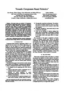
Figure 1. Simple component types used in the railcab software
We first present the specification language for the component structures in Section 2. In Section 3, we present the graphical transformation language. Thereafter, we sketch the application of the transformations on component structures in Section 4. We conclude the paper in Section 5 and provide an outlook on planned future work. 1
VCtrl
Figure 1 shows the component types which are used in our convoy example. The VCtrl and VRef components are used to control the velocity of a railcab which is driving alone or as the first railcab in a convoy. The PosCtrl is in contrast used for controlling the railcab’s position in a convoy.
www.railcab.de/en/
2
R
The and PosCalc components are used by the convoy-leader railcab to compute the position of the following railcabs in the convoy. For each following railcab, one PosCalc component instance is employed. This component computes the required position of a railcab in a convoy based on the position of the railcab directly ahead.
acceleration values to other parts of the software to control the engine. 2.3. Component Instances After presenting the component type specification, Figure 3 shows the component instance structure for three railcabs in convoy mode. The component instance structure for the leading railcab is shown on the left hand side whereas the component instances of the following railcabs is shown on the right side. In the next section, we present the transformation specifications for the reconfiguration of the leading railcab when a new railcab enters such a convoy.
2.2. Hierarchical Component Types The power of component-based software development stems from the independent reuse of components by third parties [16], i.e. larger components are built from smaller ones by connecting them via contractually specified interfaces. The UML supports this approach by their concept of composite structures [13]. Composite structures contain instances of other components which are called Parts. These parts as well as the connectors which connect these parts have multiplicity attributes. Thus, a part can express multiple component instances (of the same type). The same applies for the connector respectively the connector ends which bind the connector to the ports. For the specification of hierarchical component types in the Mechatronic UML, we simply reuse these UML concepts. Railcab
convoyLeader:Railcab
VCurrent
1
:∫
1
:VRef
:PosCalc a
:PosCtrl
a
Figure 3. Component instance structure for a convoy of three railcabs.
3. Structural Transformations 1
:PosCalc
1 1
:VCtrl
Our approach for the specification of structural transformations is twofold. Single transformations are specified by a graphical language which is based on graph transformations [15]. These single transformations are embedded into the activities of UML like activity diagrams. Activity diagrams allow to combine single transformations for a sequential execution including if-expressions and loops. Graph transformations [15] are a powerful formalism for the specification of structural changes to graph like structures. Graph transformation rules consist of structural specifications for a precondition and a postcondition. A graph transformation rule is applicable if each element of the precondition structure can be mapped onto one element of the host graph. No two elements of the precondition structure may be mapped onto the same element of the host graph (isomorphism check). Then, the host graph is changed in such a way that each element of the postcondition can be mapped onto an element of the host graph while retaining the
1
pos
1
a
1
:VRef 1 1
1
1 1
a
third:Railcab :VCtrl
1
PosRef
:PosCtrl pos
next
1
1
:PosCalc
next
1
PosCurrent
pos :∫
1 1
second:Railcab
VCurrent
1 :PosCtrl
Figure 2. Specification of a railcab’s software structure
Figure 2 shows the hierarchical Railcab component type. This component type contains different parts of the aforementioned component types. All those parts have the default multiplicity of 0..1 except the :PosCalc part which can be instantiated multiple times. This is denoted by the second frame. The pos port is a multiport. Each instance of this multiport is used to connect to a different following railcab. The a port is used to send 3
Railcab::addFollower(Railcab newRailcab, PosCalc newCalc, int positionInConvoy)
get first PosCalc [counter < positionInConvoy-1] this get next PosCalc :∫
first:PosCalc next first
next:PosCalc
1: counter := 1 1: counter++
2: first := next
[else]
add newCalc this next
first
newRailcab
newCalc pos
PosRef
next next
next:PosCalc
Figure 4. Adding a new railcab to a convoy of at least two railcabs.
element mappings created during the precondition mapping and removing elements which are part of the pre- but not part of the postcondition structure. Story patterns [5] are employed as concrete formalism. Story patterns combine pre- and postcondition structures into a single diagram based on UML [13] collaboration diagrams. The difference between pre- and postcondition structures is denoted by annotating elements by �create� and �destroy� stereotypes. An element annotated by �create� will be created during application of the story pattern, whereas an element annotated by �destroy� will be destroyed. In contrast to [5], we employ graph transformations on component instance structures instead of object structures. Figure 4 shows the transformation which specifies the component reconfiguration of the leader railcab when another railcab enters a convoy of at least two railcabs. This transformation takes three arguments: (1) the new railcab’s software component, (2) the position calculation component for the new railcab, and (3) the position in the convoy. The transformation is basically divided into two parts. In the upper half of the transformation, the component structure of the leading railcab is searched for the correct place for adding the position calculation component of the new
railcab. This is specified as a loop in the control flow. This search starts with the first position calculation component in the first activity. Then the list of position calculation components is traversed until the appropriate place between the positionInConvoy-1-th component and the next one is found. There, the new position calculation component is inserted into the component structure as shown in the lower half of Figure 4. This includes reconnecting the different components denoted by the various deleted and created connectors. Note that the next component is optional (denoted by dashed lines), i.e. only if there is such a next component, the creation and deletion of the connectors associated with this component are executed. This allows adding a railcab at the rear-end of the convoy. Additionally, a new pos port is created and connected to the new railcab’s software component.2 This activity completes the reconfiguration. We omit appropriate error handling activities due to space restrictions. This transformation is used whenever a single railcab enters a convoy of n railcabs resulting in a convoy of length n + 1. Therefore, this example transformation shows that our approach is not 2 We assume here that the underlying communication framework transparently handles the necessary inter node communication.
4
concrete syntax
Railcab
r:Railcab
new:Railcab
abstract syntax
:Component name = „Railcab“
:ComponentInstance name = „r“
:ComponentOccurence name = „new“ modifier = CREATE
mapping
abstract concrete syntax syntax
Component
ComponentInstance
ComponentOccurence
:ComponentInstance
:UMLClass name = „Component“
:UMLClass name = „ComponentInstance“
:UMLClass name = „ComponentOccurence“
:UMLObject modifier = CREATE
Figure 5. Mapping from Transformation Language to Transformations on Meta-Model.
restricted to the specification of a predefined set of component configurations but can in principle be used to specify an infinite amount of configurations. This clearly does not hold in real life. The relevant restrictions for the application in the embedded real-time domain have been presented for a similar transformation language in [17].
stance model and the graph transformations on the component structure. Based on the meta-model of the component models, we can then map the graph transformations on the component structure to graph transformations on the meta-model. For example, new:Railcab with modifier CREATE is mapped to :UMLObject with modifier CREATE and appropriate other objects e.g. concerning the Railcab component type which are not shown due to space reasons. This mapping allows the execution of the component structure transformations on component instance structures by simply reusing the concepts of [5].
4. Applying Graph Transformations on Components In Section 3, we have described how we apply graph transformations on component structures. The presented approach enables the consistent usage of graph transformations on component instance structures by applying the graph transformations directly on the concrete syntax of component instance structures instead of object structures. Internally, we map the transformations on component structures to graph transformations on object structures of the component meta-model (cf. Figure 5). First, we distinguish between the model and the meta-model level. On both levels, we differ between concrete syntax and abstract syntax. The developer of a component based system is working on the model level and uses the concrete syntax. The concrete syntax of a component type is represented by a rectangle, a name (e.g. Railcab) and a component icon at the top right corner. The abstract syntax of the Railcab component is presented by an instance of the Component meta-class with Railcab as value for the name attribute. The same (meta-) modeling approach applies for the component in-
5. Conclusions and Future Work We presented an approach which facilitates the component-based modeling of reconfigurable systems. The approach supports the definition of hierarchical component types as well as a transformation language to specify the reconfiguration of component structures. In contrast to related work, the approach supports a powerful specification language for transformations on component structures combined with a control flow specification to express if- and loopconstructs. The sketched mapping of component structure transformations based on the meta-model for the execution of the transformations is rather simple. Specifically, it does not take the special characteristics of advanced technical systems like hard deadlines and real-time scheduling into account. Therefore, further research is required for an execution of the transformations during runtime. 5
Tool support for the presented concepts and graphical specification languages is under way. It is currently integrated into our case tool Fujaba Real-Time Tool Suite3 which is currently ported to the eclipse version of core Fujaba4 .
[7] Holger Giese, Matthias Tichy, Sven Burmester, Wilhelm Sch¨ afer, and Stephan Flake. Towards the Compositional Verification of RealTime UML Designs. In Proc. of the 9th European software engineering conference held jointly with 11th ACM SIGSOFT international symposium on Foundations of software engineering (ESEC/FSE-11), pages 38–47. ACM Press, September 2003.
References [1] Basil Becker, Dirk Beyer, Holger Giese, Florian Klein, and Daniela Schilling. Symbolic Invariant Verification for Systems with Dynamic Structural Adaptation. In Proc. of the 28th International Conference on Software Engineering (ICSE), Shanghai, China. ACM Press, 2006.
[8] Klaus Grimm. Software technology in an automotive company: major challenges. In ICSE ’03: Proceedings of the 25th International Conference on Software Engineering, pages 498– 503, Washington, DC, USA, 2003. IEEE Computer Society.
[2] Jeremy S. Bradbury, James R. Cordy, Juergen Dingel, and Michel Wermelinger. A survey of self-management in dynamic software architecture specifications. In Proceedings of the 1st ACM SIGSOFT workshop on Self-managed systems (WOSS ’04), pages 28–33, New York, NY, USA, 2004. ACM Press.
[9] Bernd Hardung, Thorsten K¨ olzow, and Andreas Kr¨ uger. Reuse of software in distributed embedded automotive systems. In EMSOFT ’04: Proceedings of the 4th ACM international conference on Embedded software, pages 203–210, New York, NY, USA, 2004. ACM Press. [10] Mohamed Hadj Kacem, Ahmed Hadj Kacem, Mohamed Jmaiel, and Khalil Drira. Describing dynamic software architectures using an extended uml model. In SAC ’06: Proceedings of the 2006 ACM symposium on Applied computing, pages 1245–1249, New York, NY, USA, 2006. ACM Press.
[3] Sven Burmester and Holger Giese. Visual Integration of UML 2.0 and Block Diagrams for Flexible Reconfiguration in Mechatronic UML. In Proc. of the IEEE Symposium on Visual Languages and Human-Centric Computing (VL/HCC’05), Dallas, Texas, USA, pages 109– 116. IEEE Computer Society Press, September 2005.
[11] Jeff Magee, Naranker Dulay, and Jeff Kramer. Regis: A constructive development environment for distributed programs. Distributed Systems Engineering Journal, 1(5):304–312, September 1994.
[4] Sven Burmester, Holger Giese, and Matthias Tichy. Model-Driven Development of Reconfigurable Mechatronic Systems with Mechatronic UML. In Uwe Assmann, Arend Rensink, and Mehmet Aksit, editors, Model Driven Architecture: Foundations and Applications, volume 3599 of Lecture Notes in Computer Science, pages 47–61. Springer Verlag, August 2005.
[12] Daniel Le M´ etayer. Describing software architecture styles using graph grammars. IEEE Transactions on Software Engineering, 24(7):521–533, 1998. [13] Object Management Group. UML 2.0 Superstructure Specification, October 2004. Document: ptc/04-10-02 (convenience document).
[5] T. Fischer, J. Niere, L. Torunski, and A. Z¨ undorf. Story Diagrams: A new Graph Rewrite Language based on the Unified Modeling Language. In G. Engels and G.Rozenberg, editors, Proc. of the 6th International Workshop on Theory and Application of Graph Transformation (TAGT), Paderborn, Germany, LNCS 1764. Springer Verlag, 1998.
[14] Object Management Group. Systems Modeling Language (SysML) Specification, May 2006. [15] G. Rozenberg, editor. Handbook of Graph Grammars and Computing by Graph Transformation : Foundations. World Scientific Pub Co, February 1997. Volume 1.
[6] Holger Giese, Sven Burmester, Wilhelm Sch¨ afer, and Oliver Oberschelp. Modular Design and Verification of ComponentBased Mechatronic Systems with OnlineReconfiguration. In Proc. of 12th ACM SIGSOFT Foundations of Software Engineering 2004 (FSE 2004), Newport Beach, USA, pages 179–188. ACM Press, November 2004.
[16] Clemens Szyperski. Component Software, Beyond Object-Oriented Programming. AddisonWesley, 1998. [17] Matthias Tichy, Holger Giese, and Andreas Seibel. Story Diagrams in Real-Time Software. In Holger Giese and Bernhard Westfechtel, editors, Proc. of the 4th International Fujaba Days 2006, Bayreuth, Germany, volume tr-ri-06-275 of Technical Report, pages 15–22. University of Paderborn, September 2006.
3 http://wwwcs.uni-paderborn.de/cs/fujaba/ projects/realtime/ 4 http://wwwcs.uni-paderborn.de/cs/fujaba/ projects/eclipse/
6